EP0856395A2 - Presse à table rotative - Google Patents
Presse à table rotative Download PDFInfo
- Publication number
- EP0856395A2 EP0856395A2 EP98250015A EP98250015A EP0856395A2 EP 0856395 A2 EP0856395 A2 EP 0856395A2 EP 98250015 A EP98250015 A EP 98250015A EP 98250015 A EP98250015 A EP 98250015A EP 0856395 A2 EP0856395 A2 EP 0856395A2
- Authority
- EP
- European Patent Office
- Prior art keywords
- pressure roller
- drive
- rotor
- rotary press
- roller unit
- Prior art date
- Legal status (The legal status is an assumption and is not a legal conclusion. Google has not performed a legal analysis and makes no representation as to the accuracy of the status listed.)
- Granted
Links
Images
Classifications
-
- B—PERFORMING OPERATIONS; TRANSPORTING
- B30—PRESSES
- B30B—PRESSES IN GENERAL
- B30B15/00—Details of, or accessories for, presses; Auxiliary measures in connection with pressing
- B30B15/0023—Drive arrangements for movable carriers, e.g. turntables
-
- B—PERFORMING OPERATIONS; TRANSPORTING
- B30—PRESSES
- B30B—PRESSES IN GENERAL
- B30B11/00—Presses specially adapted for forming shaped articles from material in particulate or plastic state, e.g. briquetting presses, tabletting presses
- B30B11/02—Presses specially adapted for forming shaped articles from material in particulate or plastic state, e.g. briquetting presses, tabletting presses using a ram exerting pressure on the material in a moulding space
- B30B11/08—Presses specially adapted for forming shaped articles from material in particulate or plastic state, e.g. briquetting presses, tabletting presses using a ram exerting pressure on the material in a moulding space co-operating with moulds carried by a turntable
-
- B—PERFORMING OPERATIONS; TRANSPORTING
- B30—PRESSES
- B30B—PRESSES IN GENERAL
- B30B15/00—Details of, or accessories for, presses; Auxiliary measures in connection with pressing
- B30B15/0076—Noise or vibration isolation means
Definitions
- the invention relates to a rotary press, especially for the production of tablets, with a Frame, a rotor with drive, at least one Pressure roller unit and a housing.
- Rotary presses consist of a frame, a rotor with drive, upper and lower rockers, which guide the upper and lower pressure rollers, a frame housing, corner connectors and a head plate consist.
- the forces occurring in the pressing process are about the stamp and the wings in the headstock and initiated the frame immediately and excite these membrane-like components by the pressing forces to vibrations, which in turn leads to considerable noise emissions to lead.
- a rotary press of the generic type is out the US-PS 3,891,375 previously known.
- the Base frame made of a rectangular frame, on the The rotor is mounted on the upper frame plate consists of brackets screwed onto the frame, which carry a control unit above the rotor.
- the pressure roller units are frame-like and on the side, screwed to the frame Carriers stored.
- the disadvantage here is the absorption of the compressive forces of the two pressure roller units from which the housing forming supports, which makes it suitable for high loads to deformation of the housing and related Vibrations and noise of the housing comes.
- the invention is therefore based on the object a rotary press of the generic type in this regard to improve the inclusion of the in the Forces introduced by pressure rollers is improved and which works with less vibrations and less noise.
- the invention provides that one the rotor with drive and the pressure roller unit absorbing solid, bending and torsion resistant base plate picked up from the base frame by means of elastic bearings is, the rigidity of this elastic Bearings and the mass of this complete press cell on each other are tuned that the natural frequency of this Vibration system in all six possible degrees of freedom much smaller than the lowest The lowest stamp engagement frequency occurring at the speed as the excitation frequency.
- the complete press cell will thereby excited supercritically during the pressing process.
- An impact from dynamic forces from the pressing process not on components of the rotary press arranged on the base plate almost does not take place. That’s how she works Tablet press low vibration and low noise and can nevertheless transmit large pressing forces.
- the housing is only connected to the base frame and compared to the base plate by means of smaller ones supported elastic bearing, the stiffness of the elastic bearing is chosen so that from the connected Mass and stiffness of the elastic The resulting natural frequency is much lower than the lowest punch engagement frequency. So there are almost no vibrations and therefore almost no noise from the press forces Vibrations excited parts, such as rotor with drive and pressure roller unit, transferred to the housing.
- the housing is designed so that the upper Head part of the machine receiving part of this housing extends over the entire height of the machine and the machine is limited on one vertical side.
- This housing segment is preferably used for recording the main electric drive, the incoming and outgoing connection lines, the supply units and the supply lines of the machine.
- a wall separates this supply side of the rotary press from the clean room side of the press cell.
- the elastic bearings are as two metallic bearing elements and one connecting them elastic buffer trained.
- Such elastic bearings are under the SCHWINGMETALL brand from the company Continental.
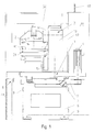
- the rotary press comprises a massive, bending and torsionally rigid base plate 1, a rotor 2, a Pressure roller unit 3 and a drive motor 4, the are stored on the solid base plate 1, and a base frame 6 standing on elastic feet 5, on which the massive base plate 1 by means of elastic Bearing 7 is mounted, and a surrounding these components Housing 8 that by means of smaller elastic bearings 9 is connected to the base frame 6.
- a bearing bush 11 for the axis 12 of here Not shown rotor 2 arranged on the solid base plate 1 a bearing bush 11 for the axis 12 of here Not shown rotor 2 arranged.
- the axis 12 of the rotor 2 carries on the underside of the base plate 1 a toothed belt pulley 13.
- the pressure roller unit 3 is included upper and lower pressure roller 14, 15 adjustable stored.
- the massive one Base plate 1 attached drive motor 4 with on the Bottom toothed belt pinion 16, with a Toothed belt 17 around the toothed belt pulley 13 for the Rotor 2 and the toothed belt pinion 16 put around and is tensioned by a spring washer 18.
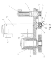
- elastic bearings 7 support the massive base plate 1 on the base frame 6 shown in FIG. 1 elastic bearings 7 are made of two metallic bearing elements 19, 20 and an elastic connecting them Buffer 21 formed.
- the elastic bearings 7 are under the brand SCHWINGMETALL from Continental customary.
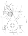
- Fig. 3 shows the bottom view of the massive, bending and torsionally rigid base plate 1 with the four elastic bearings 7, the rotor 2 driving large toothed belt pulley 13, which from the drive motor 4th driven toothed belt pinion 16 and the toothed belt 17 exciting clamping washer 18.
- Under one Angle of approximately 35 ° to the longitudinal axis 22 of the base plate 1 extend elongated holes 23, the receiving and Storage each serve a pressure roller unit 3, the is described in more detail below with reference to FIG. 4.
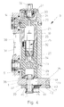
- the pressure roller unit 3 of the rotary press exists from a solid, cylindrical section Guide column 10, in its cylindrical Interior 26 is also cylindrical and hollow trained upper pressure roller receptacle 24 and one cylindrical and internally hollow lower pressure roller holder 25 are slidably mounted, the upper and lower pressure roller receptacles 24, 25 also are solid and stable.
- the guide column 10 In the upper area the guide column 10 are an adjustment drive 27 for the upper pressure roller 14 and in the central area of the Guide column 10, an actuator 28 for the lower Pressure roller 15 arranged.
- the upper adjustment drive 27 is used to adjust the upper pressure roller 14 and hence the immersion depth of the from the upper pressure roller 14 acted upon upper stamp 30 and for common i.e. parallel adjustment of upper and lower Pressure roller 14 or 15 with a fixed distance and thus to Press zone adjustment.
- the adjustment drive 28 for the lower pressure roller 15 is used to adjust the Tablet thickness relative to upper pressure roller 14.
- the two adjustment drives 27, 28 each exist from a geared motor 32 with drive spindle 33, the engages in a spindle nut 34 which is fixed to the Pressure roller receptacle 24, 25 is connected.
- the upper pressure roller receptacle 24 with the pressure roller axis 29 for the upper pressure roller 14 and the lower pressure roller holder 25 with the pressure roller axis 29 for the lower pressure roller 15 within the Guide column 10 can be moved adjustable.
- the pressure roller unit 3 is with its guide column 10 standing vertically on the solid base plate 1 stored and working horizontally Adjustment drive 35 movable. Inside the lower one The end of the guide column 10 is a truncated cone Mounting flange 36 by means of three distributed around the circumference Ring segments 46 set. In the mounting flange 36 is within the central axis of the Guide column 10 a tie rod 37 screwed in a neck 38 at the lower end of the truncated cone Fastening flange 36 penetrates the is movable within an elongated hole 23 which in the massive base plate 1 is introduced.
- the tie rod 37 is below the base plate 1 of the wedge 39 within of the stop ring 40 penetrated by means of a Dome piece 41 held by the T-head of the tie rod 37 is.
- the wedge 39 is by means of a screw spindle 42 detachable and pullable, which at the free end in one vertical bolts 47 fixed in the base plate 1 rotatable and horizontally immovable.
- To the The screw spindle 42 is locked on a spindle head 43 rotated until the neck 38 of the Mounting flange 36 and the stop ring 40 on strike the left end of slot 23. It presses the spindle 42 under the action of a compression spring 44 Tip 45 against the tie rod 37.
- the wedge 39 moved to the left so that the guide column 10 by means of the tie rod 37 firmly on the top of the Base plate 1 of the rotary tablet press is seated.
- Fig. 1 shows one in Fig. 1 on the left below the base plate 1 and next to the base frame 6 and extending right behind the pressure roller unit 3 Partition 48 which seals the housing 8 on all sides encloses.
- the partition 48 can be an on-site wall and allows the rotary press to be subdivided in one in Fig. 1 to the right of the partition 48 a multifunction column 51 and in one below the base plate 1 located supply area and a clean room area located above the base plate 1 with that of the rotor 2 and the pressure roller unit 3 press cell formed.
- the clean room area the press cell is through the base plate 1, which is in Fig. 1 wall 49 of the multifunction column shown on the left 51, the head 50 and the partition 48 from the service area Cut.
- the coverage area be used regardless of the clean room area, around the bottom and back of the rotary press located mechanical and electrical drives and Supply units from outside the clean room too serve.
- the energy supply to the rotary press can from above or below directly into the multifunction column 51 take place.
Landscapes
- Engineering & Computer Science (AREA)
- Mechanical Engineering (AREA)
- Press Drives And Press Lines (AREA)
- Medical Preparation Storing Or Oral Administration Devices (AREA)
- Presses And Accessory Devices Thereof (AREA)
- Battery Electrode And Active Subsutance (AREA)
- Glanulating (AREA)
Applications Claiming Priority (2)
| Application Number | Priority Date | Filing Date | Title |
|---|---|---|---|
| DE19705094A DE19705094C1 (de) | 1997-01-31 | 1997-01-31 | Rundlaufpresse |
| DE19705094 | 1997-01-31 |
Publications (3)
| Publication Number | Publication Date |
|---|---|
| EP0856395A2 true EP0856395A2 (fr) | 1998-08-05 |
| EP0856395A3 EP0856395A3 (fr) | 1999-01-07 |
| EP0856395B1 EP0856395B1 (fr) | 2003-09-17 |
Family
ID=7819864
Family Applications (1)
| Application Number | Title | Priority Date | Filing Date |
|---|---|---|---|
| EP98250015A Expired - Lifetime EP0856395B1 (fr) | 1997-01-31 | 1998-01-19 | Presse à table rotative |
Country Status (5)
| Country | Link |
|---|---|
| US (1) | US6116889A (fr) |
| EP (1) | EP0856395B1 (fr) |
| JP (1) | JP3820021B2 (fr) |
| DE (2) | DE19705094C1 (fr) |
| ES (1) | ES2207790T3 (fr) |
Cited By (2)
| Publication number | Priority date | Publication date | Assignee | Title |
|---|---|---|---|---|
| EP2020289A2 (fr) | 2007-08-03 | 2009-02-04 | Fette GmbH | Bâti pour une presse rotative de production de comprimés |
| CN107160153A (zh) * | 2017-06-12 | 2017-09-15 | 柳州市泰坦宇翔钢圈有限公司 | 压装机 |
Families Citing this family (12)
| Publication number | Priority date | Publication date | Assignee | Title |
|---|---|---|---|---|
| US6830442B2 (en) * | 2001-08-09 | 2004-12-14 | William Alvin Cecil | Rotary tablet press |
| DE10326175B3 (de) | 2003-06-10 | 2005-02-10 | Siemens Ag | Tablettenpresse |
| DE102004040163C5 (de) | 2004-08-19 | 2009-06-18 | Fette Gmbh | Rundläufertablettenpresse |
| DE102007034359B3 (de) * | 2007-07-24 | 2008-11-13 | Fette Gmbh | Anlage zur Herstellung von Preßlingen aus Pulvermaterial, insbesondere von Tabletten |
| DE102007057791B4 (de) * | 2007-11-30 | 2010-12-16 | Fette Gmbh | Rundlaufpresse |
| US8062015B2 (en) | 2008-09-19 | 2011-11-22 | Elizabeth-Hata International | Tablet press assembly |
| DE102009020196A1 (de) | 2009-05-07 | 2010-11-11 | Korsch Ag | Rundlaufpresse insbesondere zur Herstellung von Tabletten |
| US8607607B1 (en) | 2009-06-18 | 2013-12-17 | Elizabeth-Hata International | System and method for feeding wire material to a rotary press |
| DE102012012575B4 (de) | 2012-06-13 | 2014-09-25 | Jürgen Pagel | Zahndruckrolle und Profildruckrolle für eine Rundläuferpresse sowie Rundläuferpresse |
| EP3072675A1 (fr) * | 2015-03-27 | 2016-09-28 | Korsch AG | Presse rotative dotée d'au moins une station de rouleaux presseurs pouvant être fixée sur une plaque de support et procédé de fixation et de libération de la station de rouleaux presseurs |
| US11181442B2 (en) * | 2019-04-18 | 2021-11-23 | Dalian University Of Technology | Six-DOF motion testing and motion parameter decoupling method for rotors based on shaft-disk |
| CN120080592B (zh) * | 2025-04-23 | 2026-01-09 | 东南大学 | 一种智能压片装置 |
Family Cites Families (11)
| Publication number | Priority date | Publication date | Assignee | Title |
|---|---|---|---|---|
| US2997741A (en) * | 1959-01-20 | 1961-08-29 | John Holroyd & Company Ltd | Rotary compacting machines |
| NL131021C (fr) * | 1960-08-12 | |||
| FR1378044A (fr) * | 1963-05-30 | 1964-11-13 | Firme Helmut Hattler | Presse à excentrique composée du bas de la presse et du bâti comportant la machine |
| US3347502A (en) * | 1965-01-18 | 1967-10-17 | Lord Corp | Mounting system for looms and the like |
| DE6928976U (de) * | 1968-07-25 | 1969-11-13 | Manesty Machines | Umlaufende tablettiermaschine |
| US3625466A (en) * | 1970-08-20 | 1971-12-07 | Marshall Research & Dev Corp | Vibration isolator |
| US3891375A (en) * | 1974-01-21 | 1975-06-24 | Vector Corp | Tablet press |
| DE2520691C3 (de) * | 1975-05-09 | 1980-07-24 | Wilhelm Fette Gmbh, 2053 Schwarzenbek | Schutzhaube für Tablettenpressen |
| EP0122951A1 (fr) * | 1983-04-22 | 1984-10-31 | L. SCHULER GmbH | Dispositif de montage à isolation de vibrations pour des presses |
| US4729859A (en) * | 1985-06-12 | 1988-03-08 | C-Tec, Inc. | Method for casting concrete panels |
| DE4407127A1 (de) * | 1994-03-04 | 1995-09-07 | Rampf Formen Gmbh | Vorrichtung zur Herstellung von Formkörpern aus insbesondere Beton |
-
1997
- 1997-01-31 DE DE19705094A patent/DE19705094C1/de not_active Expired - Fee Related
-
1998
- 1998-01-19 ES ES98250015T patent/ES2207790T3/es not_active Expired - Lifetime
- 1998-01-19 DE DE59809603T patent/DE59809603D1/de not_active Expired - Lifetime
- 1998-01-19 EP EP98250015A patent/EP0856395B1/fr not_active Expired - Lifetime
- 1998-01-21 US US09/010,524 patent/US6116889A/en not_active Expired - Lifetime
- 1998-01-30 JP JP03425298A patent/JP3820021B2/ja not_active Expired - Lifetime
Cited By (6)
| Publication number | Priority date | Publication date | Assignee | Title |
|---|---|---|---|---|
| EP2020289A2 (fr) | 2007-08-03 | 2009-02-04 | Fette GmbH | Bâti pour une presse rotative de production de comprimés |
| DE102007036658A1 (de) | 2007-08-03 | 2009-02-05 | Fette Gmbh | Gestell für eine Rundläufertablettenpresse |
| DE102007036658B4 (de) * | 2007-08-03 | 2009-07-16 | Fette Gmbh | Gestell für eine Rundläufertablettenpresse |
| EP2020289A3 (fr) * | 2007-08-03 | 2011-01-05 | Fette GmbH | Bâti pour une presse rotative de production de comprimés |
| CN107160153A (zh) * | 2017-06-12 | 2017-09-15 | 柳州市泰坦宇翔钢圈有限公司 | 压装机 |
| CN107160153B (zh) * | 2017-06-12 | 2019-06-18 | 柳州市泰坦宇翔钢圈有限公司 | 压装机 |
Also Published As
| Publication number | Publication date |
|---|---|
| EP0856395A3 (fr) | 1999-01-07 |
| JP3820021B2 (ja) | 2006-09-13 |
| DE59809603D1 (de) | 2003-10-23 |
| DE19705094C1 (de) | 1998-07-09 |
| EP0856395B1 (fr) | 2003-09-17 |
| ES2207790T3 (es) | 2004-06-01 |
| US6116889A (en) | 2000-09-12 |
| JPH10216994A (ja) | 1998-08-18 |
Similar Documents
| Publication | Publication Date | Title |
|---|---|---|
| EP0856395B1 (fr) | Presse à table rotative | |
| EP1082185B1 (fr) | Presse d'emboutissage profond comportant un mouton et un coussin d'emboutissage entraines par des broches filetees et des ecrous de broche | |
| EP1050393B1 (fr) | Dispositif de production de vibrations pour moule | |
| WO1999043464A2 (fr) | Machine a transfert rotatif | |
| WO2013056805A1 (fr) | Presse | |
| EP0207150B1 (fr) | Robots industriels pour differentes applications | |
| EP1118104B2 (fr) | Dispositif de montage | |
| EP2768662B1 (fr) | Presse | |
| DE10192244B4 (de) | Nachführvorrichtung | |
| EP0517003A2 (fr) | Cellule de fabrication flexible | |
| CH678612A5 (de) | Revolver-stanzpresse. | |
| EP0856394B1 (fr) | Unité comportant des rouleaux de pressage | |
| EP3713691B1 (fr) | Machine à énucléer destinée à énucléer des pièces moulées et procédé de fabrication de pièces moulées | |
| DE2438527A1 (de) | Lagerung fuer spinnturbinen einer offenend-spinnmaschine | |
| EP1683602B1 (fr) | Bâti pour machine-outil | |
| EP2020289B1 (fr) | Bâti pour une presse rotative de production de comprimés | |
| DE69204979T2 (de) | Electrische entladungsbearbeitungsvorrichtung. | |
| DE102013012085A1 (de) | Presse zur Herstellung eines Presslings aus pulverförmigem Material | |
| EP2193006A2 (fr) | Machine, en particulier machine-outil | |
| DE10201008A1 (de) | Hubsystem für eine Plattform und Wägesystem mit einem solchen | |
| EP1715182A1 (fr) | Dispositif pour supporter et aligner un générateur d'une éolienne | |
| DE29616881U1 (de) | Höhenverstellbarer Tisch für ein Mikrotom | |
| DE2523732C3 (de) | Anlage zum Abteufen in den Boden und Herausziehen aus dem Boden von Tragoder Hilfselementen, die bei der Herstellung von Pfahlgründungen verwendet werden | |
| CH664017A5 (de) | Einrichtung zur durchfuehrung von optischen untersuchungen. | |
| DE19949473C1 (de) | Hydraulische Tischpresse, insbesondere zum Prägen von Blechschildern |
Legal Events
| Date | Code | Title | Description |
|---|---|---|---|
| PUAI | Public reference made under article 153(3) epc to a published international application that has entered the european phase |
Free format text: ORIGINAL CODE: 0009012 |
|
| AK | Designated contracting states |
Kind code of ref document: A2 Designated state(s): BE DE ES FR GB IT |
|
| AX | Request for extension of the european patent |
Free format text: AL;LT;LV;MK;RO;SI |
|
| PUAL | Search report despatched |
Free format text: ORIGINAL CODE: 0009013 |
|
| AK | Designated contracting states |
Kind code of ref document: A3 Designated state(s): AT BE CH DE DK ES FI FR GB GR IE IT LI LU MC NL PT SE |
|
| AX | Request for extension of the european patent |
Free format text: AL;LT;LV;MK;RO;SI |
|
| 17P | Request for examination filed |
Effective date: 19990628 |
|
| AKX | Designation fees paid |
Free format text: BE DE ES FR GB IT |
|
| GRAH | Despatch of communication of intention to grant a patent |
Free format text: ORIGINAL CODE: EPIDOS IGRA |
|
| GRAS | Grant fee paid |
Free format text: ORIGINAL CODE: EPIDOSNIGR3 |
|
| GRAA | (expected) grant |
Free format text: ORIGINAL CODE: 0009210 |
|
| AK | Designated contracting states |
Kind code of ref document: B1 Designated state(s): BE DE ES FR GB IT |
|
| REG | Reference to a national code |
Ref country code: GB Ref legal event code: FG4D Free format text: NOT ENGLISH |
|
| REF | Corresponds to: |
Ref document number: 59809603 Country of ref document: DE Date of ref document: 20031023 Kind code of ref document: P |
|
| GBT | Gb: translation of ep patent filed (gb section 77(6)(a)/1977) |
Effective date: 20040115 |
|
| REG | Reference to a national code |
Ref country code: ES Ref legal event code: FG2A Ref document number: 2207790 Country of ref document: ES Kind code of ref document: T3 |
|
| ET | Fr: translation filed | ||
| PLBE | No opposition filed within time limit |
Free format text: ORIGINAL CODE: 0009261 |
|
| STAA | Information on the status of an ep patent application or granted ep patent |
Free format text: STATUS: NO OPPOSITION FILED WITHIN TIME LIMIT |
|
| 26N | No opposition filed |
Effective date: 20040618 |
|
| REG | Reference to a national code |
Ref country code: ES Ref legal event code: PC2A |
|
| REG | Reference to a national code |
Ref country code: FR Ref legal event code: PLFP Year of fee payment: 18 |
|
| PGFP | Annual fee paid to national office [announced via postgrant information from national office to epo] |
Ref country code: ES Payment date: 20150122 Year of fee payment: 18 |
|
| PGFP | Annual fee paid to national office [announced via postgrant information from national office to epo] |
Ref country code: FR Payment date: 20150115 Year of fee payment: 18 |
|
| REG | Reference to a national code |
Ref country code: FR Ref legal event code: ST Effective date: 20160930 |
|
| PG25 | Lapsed in a contracting state [announced via postgrant information from national office to epo] |
Ref country code: FR Free format text: LAPSE BECAUSE OF NON-PAYMENT OF DUE FEES Effective date: 20160201 |
|
| REG | Reference to a national code |
Ref country code: ES Ref legal event code: FD2A Effective date: 20170224 |
|
| PGFP | Annual fee paid to national office [announced via postgrant information from national office to epo] |
Ref country code: DE Payment date: 20170125 Year of fee payment: 20 |
|
| PG25 | Lapsed in a contracting state [announced via postgrant information from national office to epo] |
Ref country code: ES Free format text: LAPSE BECAUSE OF NON-PAYMENT OF DUE FEES Effective date: 20160120 |
|
| PGFP | Annual fee paid to national office [announced via postgrant information from national office to epo] |
Ref country code: BE Payment date: 20170124 Year of fee payment: 20 Ref country code: GB Payment date: 20170125 Year of fee payment: 20 |
|
| PGFP | Annual fee paid to national office [announced via postgrant information from national office to epo] |
Ref country code: IT Payment date: 20170125 Year of fee payment: 20 |
|
| REG | Reference to a national code |
Ref country code: DE Ref legal event code: R071 Ref document number: 59809603 Country of ref document: DE |
|
| REG | Reference to a national code |
Ref country code: GB Ref legal event code: PE20 Expiry date: 20180118 |
|
| REG | Reference to a national code |
Ref country code: BE Ref legal event code: MK Effective date: 20180119 |
|
| PG25 | Lapsed in a contracting state [announced via postgrant information from national office to epo] |
Ref country code: GB Free format text: LAPSE BECAUSE OF EXPIRATION OF PROTECTION Effective date: 20180118 |