EP0856424B1 - Toit coulissant pour véhicule - Google Patents
Toit coulissant pour véhicule Download PDFInfo
- Publication number
- EP0856424B1 EP0856424B1 EP98101432A EP98101432A EP0856424B1 EP 0856424 B1 EP0856424 B1 EP 0856424B1 EP 98101432 A EP98101432 A EP 98101432A EP 98101432 A EP98101432 A EP 98101432A EP 0856424 B1 EP0856424 B1 EP 0856424B1
- Authority
- EP
- European Patent Office
- Prior art keywords
- cover
- connecting arms
- resilient
- sliding roof
- constructed
- Prior art date
- Legal status (The legal status is an assumption and is not a legal conclusion. Google has not performed a legal analysis and makes no representation as to the accuracy of the status listed.)
- Expired - Lifetime
Links
- 239000004033 plastic Substances 0.000 claims description 16
- 229920003023 plastic Polymers 0.000 claims description 16
- 230000003014 reinforcing effect Effects 0.000 claims description 13
- 238000007789 sealing Methods 0.000 claims description 8
- 239000000463 material Substances 0.000 claims description 4
- 229910000831 Steel Inorganic materials 0.000 claims description 2
- 238000001746 injection moulding Methods 0.000 claims description 2
- 239000010959 steel Substances 0.000 claims description 2
- XLYOFNOQVPJJNP-UHFFFAOYSA-N water Substances O XLYOFNOQVPJJNP-UHFFFAOYSA-N 0.000 claims description 2
- 239000013536 elastomeric material Substances 0.000 claims 1
- 238000010137 moulding (plastic) Methods 0.000 claims 1
- 230000002787 reinforcement Effects 0.000 description 7
- 238000002347 injection Methods 0.000 description 6
- 239000007924 injection Substances 0.000 description 6
- 238000005538 encapsulation Methods 0.000 description 5
- 238000004519 manufacturing process Methods 0.000 description 4
- 210000001364 upper extremity Anatomy 0.000 description 3
- 229920001971 elastomer Polymers 0.000 description 2
- 239000000806 elastomer Substances 0.000 description 2
- 238000009434 installation Methods 0.000 description 2
- 238000000034 method Methods 0.000 description 2
- 239000002131 composite material Substances 0.000 description 1
- 230000008878 coupling Effects 0.000 description 1
- 238000010168 coupling process Methods 0.000 description 1
- 238000005859 coupling reaction Methods 0.000 description 1
- 238000011161 development Methods 0.000 description 1
- 230000018109 developmental process Effects 0.000 description 1
- 238000005516 engineering process Methods 0.000 description 1
- 238000001125 extrusion Methods 0.000 description 1
- 239000006260 foam Substances 0.000 description 1
- 239000002184 metal Substances 0.000 description 1
- 238000000465 moulding Methods 0.000 description 1
- 239000006223 plastic coating Substances 0.000 description 1
- 238000003825 pressing Methods 0.000 description 1
- 239000002990 reinforced plastic Substances 0.000 description 1
Images

Classifications
-
- B—PERFORMING OPERATIONS; TRANSPORTING
- B60—VEHICLES IN GENERAL
- B60J—WINDOWS, WINDSCREENS, NON-FIXED ROOFS, DOORS, OR SIMILAR DEVICES FOR VEHICLES; REMOVABLE EXTERNAL PROTECTIVE COVERINGS SPECIALLY ADAPTED FOR VEHICLES
- B60J7/00—Non-fixed roofs; Roofs with movable panels, e.g. rotary sunroofs
- B60J7/02—Non-fixed roofs; Roofs with movable panels, e.g. rotary sunroofs of sliding type, e.g. comprising guide shoes
- B60J7/04—Non-fixed roofs; Roofs with movable panels, e.g. rotary sunroofs of sliding type, e.g. comprising guide shoes with rigid plate-like element or elements, e.g. open roofs with harmonica-type folding rigid panels
- B60J7/05—Non-fixed roofs; Roofs with movable panels, e.g. rotary sunroofs of sliding type, e.g. comprising guide shoes with rigid plate-like element or elements, e.g. open roofs with harmonica-type folding rigid panels pivoting upwardly to vent mode and moving downward before sliding to fully open mode
-
- B—PERFORMING OPERATIONS; TRANSPORTING
- B60—VEHICLES IN GENERAL
- B60J—WINDOWS, WINDSCREENS, NON-FIXED ROOFS, DOORS, OR SIMILAR DEVICES FOR VEHICLES; REMOVABLE EXTERNAL PROTECTIVE COVERINGS SPECIALLY ADAPTED FOR VEHICLES
- B60J10/00—Sealing arrangements
- B60J10/80—Sealing arrangements specially adapted for opening panels, e.g. doors
- B60J10/82—Sealing arrangements specially adapted for opening panels, e.g. doors for movable panels in roofs
-
- B—PERFORMING OPERATIONS; TRANSPORTING
- B60—VEHICLES IN GENERAL
- B60J—WINDOWS, WINDSCREENS, NON-FIXED ROOFS, DOORS, OR SIMILAR DEVICES FOR VEHICLES; REMOVABLE EXTERNAL PROTECTIVE COVERINGS SPECIALLY ADAPTED FOR VEHICLES
- B60J7/00—Non-fixed roofs; Roofs with movable panels, e.g. rotary sunroofs
- B60J7/0084—Water draining for non-fixed roofs or roof panels
Definitions
- the invention relates to a sunroof, in particular a sunroof, for Vehicles with a cover that is formed in a fixed part of the vehicle roof Optionally closes the roof opening or at least partially releases it, and with one movable water channel, which is in the lid closed position below the rear edges of The lid and roof opening come to rest, via at least one connecting arm with parts of the lid or a distance from the rear edge of the lid Lid reinforcement part connected and in the lid closed position by appropriate Biasing the connecting arms against the underside of the lid and the fixed Vehicle roof part is pressed, the connecting arms as resilient connecting arms formed and held in a form-fitting manner on the cover (1) or on the cover reinforcement part are.
- Such a sunroof is known from FR-A-2 645 803.
- This one is springy Connection arm for a movable water channel designed as a separate component and by means of a bolt and a catch attached to a lid-fixed part the water channel is made using a screw connection.
- By manufacturing as a single part and the connection to the lid and the water channel is a high manufacturing and Assembly effort required.
- a similar training with stiff hinged to the lid Link arms that rigidly support the water channel is from the Japanese Utility model publication JP-U-27724/86 (JP-U-61-27724) known, which is also a vehicle sunroof concerns.
- the invention has for its object to a sunroof of the type mentioned create that allows easy installation of the gutter and its reliable function always guaranteed. This object is achieved by the characterizing features of patent claim 1. Advantageous developments of the invention are specified in the subclaims.
- the invention provides that the cover reinforcing part as one Plastic extrusion is formed on the edge of the inside of the cover, with which the resilient Link arms are firmly connected.
- This is an immediate positive Connection of the connecting arms designed as resilient connecting arms to the Cover parts or the cover reinforcing part provided, which ensures that the water channel due to the elasticity of the connecting arms in the Lid closed position always sealing against the underside of the lid and the fixed Vehicle roof part or, when the sunroof part is open, sealing against the underside alone of the fixed vehicle roof part is pressed.
- One is particularly suitable for this purpose Training of the connecting arms in the manner of a leaf spring made of sheet steel, plastic or another suitable material is formed.
- the connecting arms can also be made of a composite material, such as plastic with a Sheet metal insert or a spring wire insert.
- the advantageous special feature of a easy mounting on the lid Since the cover reinforcement part as a plastic encapsulation or molded part is formed on the edge of the inside of the lid, there is a manufacturing technology Particularly advantageous because additional installation steps save the application of Link arms on the cover by integrating the link arms into the Plastic coating, i.e. in the injection of these arms during the molding process, which is why the arms are simply positioned precisely on the inside of the lid have to. In this case, additional fastening parts, such as bolts for, are unnecessary Attachment of the connecting arms to the lid, and additional springs and the so associated additional assembly work.
- the water channel is also in one piece with on its upper edges provided sealing elements made of elastomer material and in favor of simpler Manufacture molded onto the resilient connecting arms.
- the water channel Link arms and the plastic encapsulation as a cover reinforcement in one Formed operation on the lid.
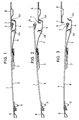
- a lid reinforcing part 3 is attached from the lid rear edge 2. It is preferred the cover reinforcing part 3 is a plastic part that is on the inside of the cover molded or formed as a foam around the inner cover sheet.
- a water channel 4 is via two laterally spaced connecting arms 5, of which in Fig. 1 to 3 only a single connecting arm 5 is shown, firmly connected to the cover 1.
- the two connecting arms 5 are arranged laterally in the rear area of the cover 1 and are positively held by the lid reinforcing part 3 or by one Plastic encapsulation or encapsulation with embedded.
- the lid reinforcement part 3 as a plastic injection molded part two connecting arms 5 embedded in the plastic encapsulation, which is a special simple assembly process for the water channel 4 and its connecting arms 5 on the cover 1 results.
- the water channel 4 preferably has a U-shaped cross section, and the two Connecting arms 5 are formed so long that the water channel 4 in the area between the Trailing edge 2 of the lid 1 and an opposite edge 7 of a fixed Vehicle roof part 8 comes to rest.
- the sunroof cover 1 closed (Fig. 1) are provided with seals 17 and 18 (FIG. 4) or as sealing lips 25 and 26 trained upper free edges (Fig. 5) of the legs of the U-shaped in cross section Gully under spring tension against the undersides of the lid 1 and the fixed Vehicle roof part 8 each pressed in the area of the edges 2 and 7 thereof.
- This Spring bias is generated by the connecting arms 5, which are resilient and are attached to or in the reinforcing part 3 under appropriate pretension, the In this state, connecting arms 5 run essentially parallel to cover 1.
- the connecting arms 5 are preferably formed as leaf springs or as leaf springs Reinforced plastic parts that are made, for example, in one piece with the Plastic material existing water channel 4 are formed.
- the water channel 4 itself is preferably with a resilient Bulging upwards.
- Fig. 2 the position of the sunroof cover 1 is shown, in which this an axis of rotation 9 is pivoted in the upward direction.
- the Water channel 4 only with its rear leg 4a behind the edge 7 on the Bottom of the fixed vehicle roof part 8 from.
- the front leg 4b of the water channel 4 is moved away from this by lifting the cover 1 and the connecting arms 5 are off deflected their parallel orientation to the lid 1, thereby pressing the water channel to one with increased force against the fixed vehicle roof part 8 and also allow an advantageous tilt position of the water channel 4, through which the front leg 4b as increased baffle serves to trap water, especially when braking over shoots the rear part of the fixed vehicle roof forward and otherwise through the Roof opening 11 could penetrate to the interior.
- the connecting arms 5 preferably near the front edge of the water channel 4 on this attached.
- a lowered position of the sunroof cover 1 is shown, in which the Water channel 4 only with its inner leg 4b through the resilient Connecting arms 5 is pressed against the inside of the lid 1; i.e. the outside Leg 4a of the water channel 4 is at a distance below the edge 7 of the vehicle fixed Roof part 8, whereby the lid 1 freely behind the fixed vehicle roof part is movable.
- the water channel 4, 14 or 24, the connecting arms 5 and a cover reinforcing part 3 as an inner cover plate with a Plastic injection molded onto the cover 1 in a single operation.
- This can on the one hand by inserting separate connecting arms 5 and preformed water channels in an injection mold or the other by forming all parts in a single Injection mold.
- a spring wire forming the connecting arms 5 can be used 12 at the same time as running across the entire length of the water channel 14 or 24 Reinforcement of the water channel formed in this case as a plastic injection molded part.
Landscapes
- Engineering & Computer Science (AREA)
- Mechanical Engineering (AREA)
- Seal Device For Vehicle (AREA)
- Vehicle Interior And Exterior Ornaments, Soundproofing, And Insulation (AREA)
Claims (8)
- Toit coulissant, notamment toit à mouvement vertical et coulissant, pour des véhicules dotés d'un panneau (1) qui, sélectivement, ferme ou dégage au moins partiellement une ouverture de toit (11) configurée dans une partie fixe (8) du toit du véhicule, et dotés d'une gouttière déplaçable (4, 14 ou 24) qui vient se placer en dessous des arêtes arrière du panneau (1) et de l'ouverture de toit (11) dans la position fermée du panneau, qui est reliée par l'intermédiaire d'au moins un bras de liaison (5) à des parties du panneau (1) ou à un élément de renforcement de panneau (3) situé à distance de l'arête arrière (2) du panneau et qui, dans la position fermée du panneau, est pressée contre le dessous du panneau (1) et de la partie arrière fixe (8) du toit du véhicule par une précontrainte correspondante des bras de liaison (5), les bras de liaison (5) étant réalisés sous forme de bras de liaison élastiques et étant maintenus en engagement positif sur le panneau (1) ou respectivement sur l'élément de renforcement de panneau (3), caractérisé en ce que l'élément de renforcement de panneau (3) est réalisé sous la forme d'un enrobage par injection de matière plastique sur le bord du côté intérieur du panneau, par lequel les bras de liaison élastiques (5) sont fixement assemblés.
- Toit coulissant selon la revendication 1, caractérisé en ce que les bras de liaison (5) sont réalisés sous forme de ressorts à lame.
- Toit coulissant selon la revendication 1 ou 2, caractérisé en ce que les bras de liaison (5) sont réalisés en tôle d'acier à ressorts.
- Toit coulissant selon la revendication 1 ou 2, caractérisé en ce que les bras de liaison (5) sont réalisés en matière plastique élastique.
- Toit coulissant selon l'une quelconque des revendications 1 à 4, caractérisé en ce que les bras de liaison élastiques (5) sont incorporés dans l'enrobage par injection de matière plastique.
- Toit coulissant selon l'une quelconque des revendications 1 à 5, caractérisé en ce que la gouttière (4) et des éléments d'étanchéité prévus sur son arète supérieure sont réalisés d'un seul tenant en matériau élastomère.
- Toit coulissant selon la revendication 6, caractérisé en ce que la gouttière (4) est formée sur les bras de liaison élastiques (5).
- Toit coulissant selon l'une quelconque des revendications précédentes, caractérisé en ce que la gouttière (4, 14 ou 24) et les bras de liaison élastiques (5) sont formés sur le panneau (1) conjointement avec un élément de renforcement de panneau (3) réalisé sous forme d'enrobage par injection de matière plastique.
Applications Claiming Priority (2)
| Application Number | Priority Date | Filing Date | Title |
|---|---|---|---|
| DE19703818A DE19703818C1 (de) | 1997-02-01 | 1997-02-01 | Fahrzeug-Schiebedach |
| DE19703818 | 1997-02-01 |
Publications (3)
| Publication Number | Publication Date |
|---|---|
| EP0856424A2 EP0856424A2 (fr) | 1998-08-05 |
| EP0856424A3 EP0856424A3 (fr) | 1999-02-03 |
| EP0856424B1 true EP0856424B1 (fr) | 2003-04-09 |
Family
ID=7819048
Family Applications (1)
| Application Number | Title | Priority Date | Filing Date |
|---|---|---|---|
| EP98101432A Expired - Lifetime EP0856424B1 (fr) | 1997-02-01 | 1998-01-28 | Toit coulissant pour véhicule |
Country Status (3)
| Country | Link |
|---|---|
| US (1) | US6073994A (fr) |
| EP (1) | EP0856424B1 (fr) |
| DE (2) | DE19703818C1 (fr) |
Families Citing this family (14)
| Publication number | Priority date | Publication date | Assignee | Title |
|---|---|---|---|---|
| EP1207067B1 (fr) | 2000-11-20 | 2007-06-13 | ArvinMeritor Technology, LLC | Véhicule |
| US6860549B2 (en) * | 2000-11-20 | 2005-03-01 | Arvin Meritor Technology, Llc. | Retractable roof panel |
| DE10127117A1 (de) | 2001-06-05 | 2002-12-19 | Webasto Vehicle Sys Int Gmbh | Fahrzeugdach mit einem verstellbaren Schließelement |
| DE10159301B4 (de) * | 2001-12-04 | 2005-09-08 | Webasto Ag | Fahrzeugdach mit einem Wasserablauf für eine Dachöffnung |
| DE10203848B4 (de) * | 2002-01-31 | 2004-07-15 | Webasto Vehicle Systems International Gmbh | Schiebedach für Fahrzeuge |
| DE10303474A1 (de) * | 2003-01-29 | 2004-08-12 | Inalfa Roof Systems Group B.V. | Offendachkonstruktion für ein Fahrzeug |
| DE20321105U1 (de) * | 2003-02-19 | 2005-12-22 | Webasto Ag | Wasserauffangrinne für eine Karosserieöffnung eines Fahrzeugs |
| DE102004016031C5 (de) * | 2004-03-30 | 2008-01-24 | Magna Car Top Systems Gmbh | Dichtungsanordnung |
| DE102005001869A1 (de) * | 2005-01-14 | 2006-07-20 | Bayerische Motoren Werke Ag | Fahrzeug-Schiebedach mit einer bewegbaren Wasserrinne |
| US20080136219A1 (en) * | 2006-10-30 | 2008-06-12 | Arvinmeritor Technology, Llc | Over-molded water channel |
| DE102007015709B4 (de) * | 2007-01-25 | 2009-09-03 | Webasto Ag | Fahrzeugdach |
| EP2105333B1 (fr) | 2008-03-26 | 2012-06-20 | Inalfa Roof Systems Group B.V. | Ensemble de toit pour véhicule et son procédé de fonctionnement |
| DE102011013818B4 (de) | 2011-03-14 | 2014-03-13 | Webasto Ag | Dachanordnung |
| US9902245B2 (en) * | 2016-07-05 | 2018-02-27 | Fca Us Llc | Vehicle sunroof assembly |
Family Cites Families (8)
| Publication number | Priority date | Publication date | Assignee | Title |
|---|---|---|---|---|
| DE3238454C2 (de) * | 1982-10-16 | 1984-11-29 | Webasto-Werk W. Baier GmbH & Co, 8035 Gauting | Schiebedach für Fahrzeuge |
| JPS60106826U (ja) * | 1983-12-27 | 1985-07-20 | ダイキヨ−・ベバスト株式会社 | 乗物用サンル−フ装置の可動雨樋取付構造 |
| JPS6127724A (ja) * | 1984-07-18 | 1986-02-07 | Nissan Motor Co Ltd | 自動車ウインドモ−ル保持構造 |
| DE3740129A1 (de) * | 1987-11-26 | 1989-06-08 | Webasto Ag Fahrzeugtechnik | Schiebehebedach fuer fahrzeuge |
| DE3824942C1 (fr) * | 1988-07-22 | 1989-10-12 | Rockwell Golde Gmbh, 6000 Frankfurt, De | |
| FR2645803B1 (fr) * | 1989-04-17 | 1994-04-29 | Heuliez Henri France Design | Dispositif de fixation d'une traverse d'ecoulement d'eau sur un panneau mobile par rapport a une paroi fixe, en particulier destine a un toit ouvrant de vehicule automobile |
| JPH06127724A (ja) * | 1992-10-14 | 1994-05-10 | Mita Ind Co Ltd | 給紙装置 |
| JP2918440B2 (ja) * | 1993-12-10 | 1999-07-12 | 八千代工業株式会社 | 車両用サンルーフ装置 |
-
1997
- 1997-02-01 DE DE19703818A patent/DE19703818C1/de not_active Expired - Fee Related
-
1998
- 1998-01-28 DE DE59807785T patent/DE59807785D1/de not_active Expired - Fee Related
- 1998-01-28 EP EP98101432A patent/EP0856424B1/fr not_active Expired - Lifetime
- 1998-01-29 US US09/015,292 patent/US6073994A/en not_active Expired - Fee Related
Also Published As
| Publication number | Publication date |
|---|---|
| DE59807785D1 (de) | 2003-05-15 |
| EP0856424A2 (fr) | 1998-08-05 |
| EP0856424A3 (fr) | 1999-02-03 |
| US6073994A (en) | 2000-06-13 |
| DE19703818C1 (de) | 1998-04-02 |
Similar Documents
| Publication | Publication Date | Title |
|---|---|---|
| EP0856424B1 (fr) | Toit coulissant pour véhicule | |
| DE19820699C1 (de) | Führungskulisse für Schiebedeckel an Schiebehebedachkonstruktionen für Kraftfahrzeuge | |
| DE19730942C2 (de) | Dichtungsbaugruppe | |
| EP0716946B1 (fr) | Déflecteur de vent pour toit coulissant de véhicule automobile | |
| DE102008001956A1 (de) | Wischblatt | |
| DE3545832A1 (de) | Dichtungsanordnung fuer ein kraftfahrzeug | |
| DE4309088A1 (de) | Ortsfest einbaubare Scheibe für Kraftfahrzeuge | |
| DE19946008A1 (de) | Verbundbauteil für Fahrzeugkarosserien | |
| DE102004003568B4 (de) | Dichtungsstruktur für ein Schiebedach eines Kraftfahrzeugs | |
| DE2701432A1 (de) | Schiebedachanordnung | |
| DE102005063099B4 (de) | Windabweiser im Kraftfahrzeugbereich | |
| DE102019114304A1 (de) | Fahrzeug mit einer Dichtungsanordnung | |
| DE10116456A1 (de) | Dachmodul für ein Fahrzeug | |
| EP1389546B1 (fr) | Canal de guidage pour patins glissants pour toit ou panneau ouvrant de véhicule | |
| DE69516575T2 (de) | Befestigungselement für Kabel, Rohre oder dergleichen | |
| DE202008014739U1 (de) | Dichtungsanordnung für den Fensterschacht einer Fahrzeugtüre | |
| DE102005032437A1 (de) | Fahrzeugdach mit einem bewegbaren Dachteil | |
| DE102019124844B3 (de) | Fahrzeugdach und Dachanordnung | |
| DE102017211291B4 (de) | Fensterschachtleistenanordnung sowie Verfahren zum Herstellen einer Fensterschachtleistenanordnung | |
| DE202012103824U1 (de) | Offendachkonstruktion für ein Fahrzeug | |
| DE102016012179A1 (de) | Kraftfahrzeug | |
| DE19950812A1 (de) | Tülle mit Verbindungsabschnitt | |
| DE102011102471A1 (de) | Abdeck- und/oder Dekorleiste zum Verkleiden eines Fahrzeug-Bauteiles sowie Fahrzeug-Bauteil für eine Abdeck- und/oder Dekorleiste | |
| EP4025443B1 (fr) | Baguette profilée comportant un élément d'évacuation d'eau | |
| EP1818203A1 (fr) | Elément d'étanchéité pour une vitre |
Legal Events
| Date | Code | Title | Description |
|---|---|---|---|
| PUAI | Public reference made under article 153(3) epc to a published international application that has entered the european phase |
Free format text: ORIGINAL CODE: 0009012 |
|
| AK | Designated contracting states |
Kind code of ref document: A2 Designated state(s): AT BE CH DE DK ES FI FR GB GR IE IT LI LU MC NL PT SE |
|
| AX | Request for extension of the european patent |
Free format text: AL;LT;LV;MK;RO;SI |
|
| PUAL | Search report despatched |
Free format text: ORIGINAL CODE: 0009013 |
|
| AK | Designated contracting states |
Kind code of ref document: A3 Designated state(s): AT BE CH DE DK ES FI FR GB GR IE IT LI LU MC NL PT SE |
|
| AX | Request for extension of the european patent |
Free format text: AL;LT;LV;MK;RO;SI |
|
| AKX | Designation fees paid | ||
| RBV | Designated contracting states (corrected) |
Designated state(s): DE FR GB IT NL |
|
| 17P | Request for examination filed |
Effective date: 19990819 |
|
| 17Q | First examination report despatched |
Effective date: 20011012 |
|
| GRAH | Despatch of communication of intention to grant a patent |
Free format text: ORIGINAL CODE: EPIDOS IGRA |
|
| GRAH | Despatch of communication of intention to grant a patent |
Free format text: ORIGINAL CODE: EPIDOS IGRA |
|
| GRAA | (expected) grant |
Free format text: ORIGINAL CODE: 0009210 |
|
| AK | Designated contracting states |
Designated state(s): DE FR GB IT NL |
|
| PG25 | Lapsed in a contracting state [announced via postgrant information from national office to epo] |
Ref country code: IT Free format text: LAPSE BECAUSE OF FAILURE TO SUBMIT A TRANSLATION OF THE DESCRIPTION OR TO PAY THE FEE WITHIN THE PRE;WARNING: LAPSES OF ITALIAN PATENTS WITH EFFECTIVE DATE BEFORE 2007 MAY HAVE OCCURRED AT ANY TIME BEFORE 2007. THE CORRECT EFFECTIVE DATE MAY BE DIFFERENT FROM THE ONE RECORDED.SCRIBED TIME-LIMIT Effective date: 20030409 |
|
| REG | Reference to a national code |
Ref country code: GB Ref legal event code: FG4D Free format text: NOT ENGLISH |
|
| GBT | Gb: translation of ep patent filed (gb section 77(6)(a)/1977) | ||
| ET | Fr: translation filed | ||
| PG25 | Lapsed in a contracting state [announced via postgrant information from national office to epo] |
Ref country code: GB Free format text: LAPSE BECAUSE OF NON-PAYMENT OF DUE FEES Effective date: 20040128 |
|
| PGFP | Annual fee paid to national office [announced via postgrant information from national office to epo] |
Ref country code: DE Payment date: 20040205 Year of fee payment: 7 |
|
| PLBE | No opposition filed within time limit |
Free format text: ORIGINAL CODE: 0009261 |
|
| STAA | Information on the status of an ep patent application or granted ep patent |
Free format text: STATUS: NO OPPOSITION FILED WITHIN TIME LIMIT |
|
| 26N | No opposition filed |
Effective date: 20040112 |
|
| PG25 | Lapsed in a contracting state [announced via postgrant information from national office to epo] |
Ref country code: NL Free format text: LAPSE BECAUSE OF NON-PAYMENT OF DUE FEES Effective date: 20040801 |
|
| GBPC | Gb: european patent ceased through non-payment of renewal fee |
Effective date: 20040128 |
|
| NLV4 | Nl: lapsed or anulled due to non-payment of the annual fee |
Effective date: 20040801 |
|
| PG25 | Lapsed in a contracting state [announced via postgrant information from national office to epo] |
Ref country code: DE Free format text: LAPSE BECAUSE OF NON-PAYMENT OF DUE FEES Effective date: 20050802 |
|
| REG | Reference to a national code |
Ref country code: FR Ref legal event code: TP |
|
| REG | Reference to a national code |
Ref country code: FR Ref legal event code: ST Effective date: 20080229 |
|
| PG25 | Lapsed in a contracting state [announced via postgrant information from national office to epo] |
Ref country code: FR Free format text: LAPSE BECAUSE OF NON-PAYMENT OF DUE FEES Effective date: 20040131 |