EP0856604B1 - Verfahren zum Auswuchten einer Waschmaschine - Google Patents
Verfahren zum Auswuchten einer Waschmaschine Download PDFInfo
- Publication number
- EP0856604B1 EP0856604B1 EP97500210A EP97500210A EP0856604B1 EP 0856604 B1 EP0856604 B1 EP 0856604B1 EP 97500210 A EP97500210 A EP 97500210A EP 97500210 A EP97500210 A EP 97500210A EP 0856604 B1 EP0856604 B1 EP 0856604B1
- Authority
- EP
- European Patent Office
- Prior art keywords
- drum
- vibration
- unbalance
- washing machine
- speed
- Prior art date
- Legal status (The legal status is an assumption and is not a legal conclusion. Google has not performed a legal analysis and makes no representation as to the accuracy of the status listed.)
- Expired - Lifetime
Links
- 238000000034 method Methods 0.000 title claims description 25
- 238000005406 washing Methods 0.000 title claims description 21
- XLYOFNOQVPJJNP-UHFFFAOYSA-N water Substances O XLYOFNOQVPJJNP-UHFFFAOYSA-N 0.000 claims description 22
- 230000001133 acceleration Effects 0.000 claims description 19
- 238000009987 spinning Methods 0.000 claims description 19
- 238000005259 measurement Methods 0.000 claims description 17
- 208000012886 Vertigo Diseases 0.000 description 16
- 238000010586 diagram Methods 0.000 description 6
- 230000008569 process Effects 0.000 description 5
- 230000004913 activation Effects 0.000 description 4
- 238000004804 winding Methods 0.000 description 4
- 230000005355 Hall effect Effects 0.000 description 1
- 230000009471 action Effects 0.000 description 1
- 230000009849 deactivation Effects 0.000 description 1
- 230000001419 dependent effect Effects 0.000 description 1
- 238000001514 detection method Methods 0.000 description 1
- 230000000694 effects Effects 0.000 description 1
- 238000002474 experimental method Methods 0.000 description 1
- 238000001914 filtration Methods 0.000 description 1
- 230000006698 induction Effects 0.000 description 1
- 238000009434 installation Methods 0.000 description 1
- 230000010355 oscillation Effects 0.000 description 1
- 230000002265 prevention Effects 0.000 description 1
- 239000000758 substrate Substances 0.000 description 1
Images


Classifications
-
- D—TEXTILES; PAPER
- D06—TREATMENT OF TEXTILES OR THE LIKE; LAUNDERING; FLEXIBLE MATERIALS NOT OTHERWISE PROVIDED FOR
- D06F—LAUNDERING, DRYING, IRONING, PRESSING OR FOLDING TEXTILE ARTICLES
- D06F33/00—Control of operations performed in washing machines or washer-dryers
- D06F33/30—Control of washing machines characterised by the purpose or target of the control
- D06F33/48—Preventing or reducing imbalance or noise
-
- D—TEXTILES; PAPER
- D06—TREATMENT OF TEXTILES OR THE LIKE; LAUNDERING; FLEXIBLE MATERIALS NOT OTHERWISE PROVIDED FOR
- D06F—LAUNDERING, DRYING, IRONING, PRESSING OR FOLDING TEXTILE ARTICLES
- D06F37/00—Details specific to washing machines covered by groups D06F21/00 - D06F25/00
- D06F37/20—Mountings, e.g. resilient mountings, for the rotary receptacle, motor, tub or casing; Preventing or damping vibrations
- D06F37/22—Mountings, e.g. resilient mountings, for the rotary receptacle, motor, tub or casing; Preventing or damping vibrations in machines with a receptacle rotating or oscillating about a horizontal axis
- D06F37/225—Damping vibrations by displacing, supplying or ejecting a material, e.g. liquid, into or from counterbalancing pockets
-
- D—TEXTILES; PAPER
- D06—TREATMENT OF TEXTILES OR THE LIKE; LAUNDERING; FLEXIBLE MATERIALS NOT OTHERWISE PROVIDED FOR
- D06F—LAUNDERING, DRYING, IRONING, PRESSING OR FOLDING TEXTILE ARTICLES
- D06F34/00—Details of control systems for washing machines, washer-dryers or laundry dryers
- D06F34/14—Arrangements for detecting or measuring specific parameters
- D06F34/16—Imbalance
Definitions
- the present invention relates to a washing machine whose drum rotates about a horizontal axis, and more particularly to the prevention of vibrations in the clothes-laden drum when it rotates at high speed during the spinning stage.
- US 5,280,660 describes a method for balancing a washing machine whose drum rotates about a horizontal axis, wherein the washing machine is equipped with at least three water chambers distributed peripherally inside the drum, which chambers selectively receive a preset amount of water from their respective solenoid valves depending upon the result of the vibration measured by a vibration sensor and the drum unbalance position measured by means of a proximity sensor, the signals from both sensors being combined to select the water supply that will compensate for the unbalance, and a motor that accelerates the drum to maximum spinning speed during the compensation process.
- US 4,517,695 describes a method for balancing a washing machine whose drum rotates about a horizontal axis, wherein the drive motor is connected to a rotation speed control device that controls drum acceleration from an initial spinning speed to a final speed, depending upon the force exerted by the unbalance of the clothing and the comparison thereof with a preset value calculated for the final spinning speed.
- drum rotation is accelerated from a low initial value to a high final maximum spinning value, in spurts by means of various abrupt speed increases, and maintaining constant velocity in each spurt, in intervals whose length depends upon the result of the measurement of vibration at each constant speed value.
- a preset quantity of water is placed in the selected compensation chamber, and this action is repeated until the measured vibration value falls below a certain reference value.
- the acceleration time that transpires until the maximum speed for carrying out the compensation method is reached is excessive, because the water is added to the compensation chambers in ever-equal given doses, and because the drum undergoes successive accelerations after acceleration-free intervals.
- the object of the invention is a method for balancing the drum of a washing machine equipped with three or more hollow water chambers distributed through its internal periphery by means of compensating for unbalance while the drum accelerates from a low initial speed to a high final maximum spinning speed, while combining the addition of water to the selected water chamber, which is situated diametrically opposite the unbalanced position.
- the addition of compensating water is continuous, by means of a given flow; acceleration is likewise continuous in gradual fashion, while vibration is measured continuously, and only the rate of acceleration is dependent upon the result of the vibration measurement.
- smooth rotation is achieved without exceeding an admissible washing machine vibration value by means of drum acceleration at a gradual rate until reaching a maximum speed, while the unbalance of the clothes is compensated for in a shorter total process time.
- the drum drive motor is controlled through a voltage/frequency speed variator governed by the washing machine's electronic controller to regulate the rate of drum acceleration as a function of the result of the vibration measurement and its comparison with a preset reference value.
- the vibration reference value for comparison with the real value is changing throughout the range of spinning speeds and is reduced as the drum accelerates to maintain the unbalanced mass of the drum always below a constant value, inasmuch as vibration increases at a square rate with the drum speed.
- the speed variator also allows the torque of the drum drive motor to be raised at a speed as low as 10 r/min, to effect full water chamber emptying before beginning a new balancing process.
- the vibration sensor used to execute the method has the advantages of lower economic cost and easier installation than the accelerometers of known methods, as well as the fact that the result of measurement is not affected by the mass of the washing machine's structure, as occurs with an accelerometer, but only by the unbalance of the clothing, thus also gaining time in the execution of the compensation process until final compensation is achieved.
- FIG. 1 shows two views of the washing machine with the system for carrying out the method for balancing the washing machine drum according to the invention.
- FIG. 2 is a wiring diagram of the sensor used to measure vibration.
- FIG. 3 is a diagram of the measurement of the vibration generated by the drum unbalance combined with the measurement of the unbalance position.
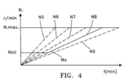
- FIG. 4 is a diagram of the different drum accelerations depending upon the unbalance, in an embodiment of the invention.
- FIG. 5 is the diagram of the steps included in the embodiment of the balancing method, according to fig. 4.
- the washing machine 1 for executing the method according to the invention is comprised of a tub 2 fixed to the washing machine structure, the drum 3 rotating about a horizontal drive axis 3 a through whose internal periphery are distributed three water chambers 4 a ,4 b ,4 c , a housing 2 a holding the bearings of the axis 3 a which is fixed to the rear of the tub 2, the induction motor 5 for driving the drum 3, the washing machine's electronic controller 6, the voltage-frequency converter speed variator 7, the device 8,9 for detecting vibration and position, and the solenoid valves 10 a ,10 b ,10 c activated individually by the controller 6 to compensate for the unbalance by means of selectively filling the chambers 4 a ,4 b ,4 c by means of water streams according to the arrows 13 in figure 1.
- the drum drive motor 5 shown in figure 1 has two windings 14,15 powered separately to achieve two ranges of drum rotation speed N, the low 35-to-55 r/min speed for clothes washing and the high spinning speed between 200 and 900 r/min, these latter two speeds being referenced respectively as Nini and Nmax. Both windings of the motor 5 are powered through the speed variator 7, the low-speed winding 14 to reduce the speed N to a very low value such as 10 r/min when the chambers 4 a ,4 b ,4 c are to be emptied, and the winding 15 to bring the speed N up gradually to spinning speed during the unbalance compensation process.
- the unbalance detection device 8,9 includes a vibration magnitude sensor 8, shown in figure 2, and a position sensor 9 to measure the position of the unbalance, shown in figure 3, which rotates of a piece with the drum axis 3 a .
- the vibration sensor 8 used for the execution of the compensation method is preferably constructed using a strain gauge 8 a and an associated circuit 8 b for filtering, amplifying and processing the output signal.
- the gauge 8 a is fixed through a substrate to the bearing-holding housing 2 a where it is easily accessible and in a place to which all radial drum vibration is transmitted.
- the circuit 8 b faithfully reproduces the oscillation of the vibration through its signal 11 of electrical voltage V oscillating between two alternating peak values +Vc and -Vc which is almost a sine function, shown in figure 3, and the numerical result of the measurement is the Vc peak to peak amplitude.
- the sensor 9 sensing the unbalance position in relation to the water chambers 4 used preferably for the execution of the method is an optic sensor where the photoelectric transmitter not shown in the figures is associated with a rotating disk fixed to the axis 3 a and perforated with a number of orifices 9 b distributed uniformly over its periphery indicating the angle rotated by the drum.
- the position sensor 9 could also be a magnetic proximity or Hall effect sensor.
- One of the perforations in the disk in sensor 9 is a long groove 9 a whose position relative to one of the chambers 4 is recorded in the controller 6, serving as a zero reference of the angle rotated by the drum 3.
- the photoelectric transmitter provides an electrical signal 12 associated with the position of the groove 9 a , and the controller 6 combines the two electrical signals 11 and 12 to measure the phase angle p hi, as shown in figure 3, between the said groove 9 a and the peak value +Vc of the vibration signal 11, to select one or two of the three chambers 4 a , 4 b , 4 c , diametrically opposite the location of the mass causing the unbalance.
- Figure 4 depicts the acceleration of the drum 3 by means of the variator 7 in an embodiment of the method 40 for balancing the drum 3 according to the flow diagram in figure 5.
- the acceleration of the drum 3 takes place smoothly, from the initial spinning speed Nini and gradually up to the maximum speed Nmax, by means of tiny successive "delta N" increments, for example increments of 50 r/min or less at a time, yielding different rates of acceleration Na as a function of the initial unbalanced mass.
- Vibration magnitude is measured between the two opposing peak values Vc of the signal from sensor 8 shown in figure 3.
- the preferred embodiment 40 of the balancing method includes prior steps 41 to 44, the balance compensating sequence of steps 45 to 50, and final steps 51 to 53, which include:
- the water flow 13 in this embodiment is supplied, step 50, to the selected chamber 4a-4c, or interrupted, step 52, according to the result of the comparison in step 49, and the result thus found conditions the activation and deactivation of the selected solenoide valves 10, since inasmuch the acceleration N8 is uninterrupted, when the measurement Vc is less than the value Vum, the valve is deactivated, step 52, and the selected chamber 4 is prevented from overloading, which could cause un unbalance in the position of the selected chamber 4 greater than the unbalance of the initial mass of clothes in the drum 3 in the opposite position.
- the measurement Vc oscillates with the course of time arround the thresold value Vum, while the acceleration N8 is continuous.
- step 53 the elapsed time t is compared with the recorded maximum spinning time t max, and the drum 3 rotates at the maximum spinning speed Nmax until the maximum spinning time t max has expired.
Landscapes
- Engineering & Computer Science (AREA)
- Textile Engineering (AREA)
- Control Of Washing Machine And Dryer (AREA)
Claims (3)
- Verfahren zum Auswuchten einer Waschmaschine, deren Trommel (3) sich um eine horizontale Achse (3a) dreht, wobei die Waschmaschine ausgestattet ist mit mindestens drei am Innenumfang verteilten Wasserkammern (4a, 4b, 4c) für den Ausgleich der Unwuchtigkeit der Trommel, einem Motor (5) mit Mitteln (7) für die gesteuerte Beschleunigung der Trommel (3), einem Sensor (8) für die Grösse der Schwingung (Vc), einem Stellungssensor (9) zur Messung der Stellung der Unwuchtigkeit am Umfang der Trommel (3), einer Steuerelektronik (6) der Waschmaschine zur Kombination der von den beiden Sensoren (8, 9) abgegebenen elektrischen Signale (11, 12), um zumindest eine der Ausgleichskammern (4a, 4b, 4c) zu wählen und dieser über ein Elektroventil (10a, 10b, 10c) eine entsprechende Wassermenge (13) zum Ausgleich der Unwuchtigkeit zuzuführen, während die Trommel zwischen einer anfänglichen und einer abschliessenden Drehgeschwindigkeit (Nanf↔Nmax) beschleunigt wird und die Steuerleketronik (6) eine Sequenz von Arbeitsgängen (45 - 50) wiederholt, zu denen die Messung (45) der Schwingung (Vc) und der Unwuchtigkeitsstellung (phi), der Vergleich (49) des sich ergebenden Schwingungsmasses (Vc) mit einem zuvor registrierten Wert (Vum) und der Vergleich (48) der tatsächlichen Geschwindigkeit (Na) der Trommel mit der höchsten Schleudergeschwindigkeit (Nmax) gehören, dadurch gekennzeichnet dass das die folgende Schritte umfasst:einem ersten Schritt zur vorherigen Identifikation (41) einer der Ausgleichskammern (4a, 4b, 4c) mit einer Referenzstellung (9a) des Stellungssensors (9) und zur Verbindung einer der Ausgleichskammern (4a, 4b, 4c) mit ihrem jeweiligen Elektroventil (10a, 10b, 10c);ein tatsächliche Beschleunigungsrhythmus (Na) wird unter einer Vielzahl von Rhythmen (N5 - N9) gewählt und ist von dem sich ergebenden Schwingungsmass (Vc) bei d.er genannten Schleudergeschwindigkeit (Nini) abhängig;während der widerholten Durchführung dieser Sequenz (45 - 50) von Arbeitsgängen zum Ausgleich der Unwuchtigkeit wird die Trommel (3) kontinuierlich in diesem Rhythmus (N5 - N9) beschleunigt, und die Wassermenge (13) gleichzeitig der ausgewählten Ausgleichs-kammer (4a, 4b, 4c) zugeführt;der fortwährend Vergleich (27, 49) des gemessenen Schwingungswertes (Vc) mit dem zuvor registrierten Schwingungswert (Vum), wobei sich dieser in Abhängigkeit von der tatsächlichen Geschwindigkeit (N) der Trommel ändert.
- Verfahren zum Auswuchten einer Waschmaschine nach Anspruch 1 dadurch gekennzeichnet, dass der tatsächlichen Beschleunigungsrhythmus (Na) der Trommel unter den verschiedenen konstanten Rhythmen (N5 - N9) ausgewählt und der Wasserstrom (13) der ausgewählten Kammer (4) zugeführt bzw. unterbrochen wird, jeweils in Abhängigkeit vom Ergebnis des Vergleichs (49) des gemessenen Schwingungswertes (Vc) mit dem zuvor registrierten Schwingungswert (Vum).
- Verfahren zum Auswuchten einer Waschmaschine nach Anspruch 1, dadurch gekennzeichnet, dass das Ergebnis der Schwingungsmessung (45) dem Mass (Vc) der Weite von Spitze zu Spitze (+Vc, -Vc) des wechselnden Signals (12) des Schwingungssensors (8) ist, welcher an dem die Kugellager der Trommel aufnehmenden Gehäuse (2a) montiert wird, während die ausgewuchtete Stellung dem Phasenmass (phi) zwischen einer der Spitzen (+Vc) und eine elektrischen Signal (11) des Stellungssensors (9) entspricht.
Applications Claiming Priority (2)
| Application Number | Priority Date | Filing Date | Title |
|---|---|---|---|
| ES9700199 | 1997-01-31 | ||
| ES009700199A ES2151332B1 (es) | 1997-01-31 | 1997-01-31 | Metodo de equilibrado de una lavadora de ropa. |
Publications (3)
| Publication Number | Publication Date |
|---|---|
| EP0856604A2 EP0856604A2 (de) | 1998-08-05 |
| EP0856604A3 EP0856604A3 (de) | 1999-06-02 |
| EP0856604B1 true EP0856604B1 (de) | 2001-09-26 |
Family
ID=8298072
Family Applications (1)
| Application Number | Title | Priority Date | Filing Date |
|---|---|---|---|
| EP97500210A Expired - Lifetime EP0856604B1 (de) | 1997-01-31 | 1997-12-04 | Verfahren zum Auswuchten einer Waschmaschine |
Country Status (3)
| Country | Link |
|---|---|
| EP (1) | EP0856604B1 (de) |
| DE (1) | DE69706956D1 (de) |
| ES (1) | ES2151332B1 (de) |
Families Citing this family (24)
| Publication number | Priority date | Publication date | Assignee | Title |
|---|---|---|---|---|
| US6477867B1 (en) * | 1998-12-23 | 2002-11-12 | Fisher & Paykel Limited | Laundry appliance |
| GB9924832D0 (en) * | 1999-10-21 | 1999-12-22 | Primus N V | Method of balancing an object which rotates about an axis |
| DE10022609C2 (de) * | 2000-05-09 | 2003-11-13 | Whirlpool Co | Verfahren zur Begrenzung der Unwuchtwirkung einer Wascheinheit einer Waschmaschine und Vorrichtung zur Durchführung des Verfahrens |
| EP1336004B1 (de) * | 2000-11-24 | 2004-09-22 | Primus N.V. | Rotierende maschinen mit auswuchtung |
| ES2277487B1 (es) * | 2004-11-08 | 2008-06-16 | Fagor, S. Coop. | Dispositivo y metodo para el equilibrado de una lavadora. |
| PL1736589T3 (pl) * | 2005-06-24 | 2015-03-31 | V Zug Ag | Pralka z detektorem niewyważenia |
| PL2010705T3 (pl) | 2006-04-13 | 2012-08-31 | Bsh Hausgeraete Gmbh | Maszyna do prania i/lub suszenia bielizny |
| NZ552422A (en) | 2006-12-21 | 2009-09-25 | Fisher & Paykel Appliances Ltd | Laundry appliance including control means which energises a motor to evenly distribute a load in response to signals from load sensors |
| AU2009327647B2 (en) | 2008-12-17 | 2012-07-19 | Fisher & Paykel Appliances Limited | A laundry machine |
| EP2206823B1 (de) | 2008-12-17 | 2014-10-29 | Fisher & Paykel Appliances Limited | Waschmaschine mit einem Gleichgewicht Verbesserungssystem |
| ITCS20110006A1 (it) * | 2011-03-02 | 2012-09-03 | Calabrian High Tech Cht S R L | Sistema di bilanciamento delle forze d'inerzia rotanti generate dalla maldistribuzione dei panni in una lavatrice |
| US8713977B2 (en) | 2010-12-08 | 2014-05-06 | Whirlpool Corporation | Laundry treating appliance with balancing system |
| US8695383B2 (en) | 2010-12-08 | 2014-04-15 | Whirlpool Corporation | Laundry treating appliance with balancing system |
| US8701451B2 (en) | 2010-12-08 | 2014-04-22 | Whirlpool Corporation | Laundry treating appliance with balancing system |
| US9003838B2 (en) | 2010-12-08 | 2015-04-14 | Whirlpool Corporation | Laundry treating appliance with balancing system |
| US8991223B2 (en) | 2010-12-08 | 2015-03-31 | Whirlpool Corporation | Laundry treating appliance with balancing system |
| CN103270208B (zh) * | 2010-12-27 | 2015-08-19 | 阿塞里克股份有限公司 | 其中不平衡负载被平衡的洗衣机 |
| US9267225B2 (en) | 2011-12-22 | 2016-02-23 | Whirlpool Corporation | Method of estimating bending moment of a laundry treating appliance drum shaft using a proximity sensor |
| EP2666899A1 (de) * | 2012-05-22 | 2013-11-27 | Whirlpool Corporation | Verfahren zur Erkennung des Zyklusendes eines Haushaltswäschemachines |
| KR102032845B1 (ko) | 2013-02-13 | 2019-10-16 | 엘지전자 주식회사 | 의류처리장치 |
| JP7100839B2 (ja) * | 2017-11-21 | 2022-07-14 | 青島海爾洗衣机有限公司 | ドラム式洗濯機 |
| JP7093069B2 (ja) * | 2017-12-20 | 2022-06-29 | 青島海爾洗衣机有限公司 | 洗濯機 |
| JP7442114B2 (ja) * | 2019-05-10 | 2024-03-04 | 青島海爾洗衣机有限公司 | 洗濯機 |
| CN112746445B (zh) * | 2020-12-25 | 2022-03-18 | 珠海格力电器股份有限公司 | 一种洗衣机控制方法、装置、电子设备及可读存储介质 |
Citations (1)
| Publication number | Priority date | Publication date | Assignee | Title |
|---|---|---|---|---|
| US4517695A (en) * | 1981-10-22 | 1985-05-21 | Hoffmann Ernst H | Method and apparatus for balancing of out-of-balance forces in centrifuges or combined washing machines-spin driers |
Family Cites Families (7)
| Publication number | Priority date | Publication date | Assignee | Title |
|---|---|---|---|---|
| GB877660A (en) * | 1958-11-28 | 1961-09-20 | Pellerin Corp Milnor | Automatic imbalance control apparatus |
| US3119773A (en) * | 1960-10-10 | 1964-01-28 | Whirlpool Co | Pivoting deflector water balance system for centrifugal extractor apparatus |
| DE2048587A1 (de) * | 1970-08-01 | 1972-02-03 | Zanussi A Spa Industrie | Vorrichtung zum selbsttätigen Auswuchten von Wasch- und Schleudermaschinen |
| IT1139366B (it) * | 1980-06-09 | 1986-09-24 | Mitsubishi Heavy Ind Ltd | Macchina per lavaggio a secco |
| CH672803A5 (en) * | 1986-02-18 | 1989-12-29 | Escher Wyss Ag | Commercial washing centrifuge balancing - by adding counter balance fluid in compensation chambers on periphery |
| IT1243140B (it) * | 1990-09-05 | 1994-05-24 | Osvaldo Tonello | Sistema di rilevamento e di correzione dello squilibrio durante la centrifuga in macchine lavatrici industriali |
| US5280660A (en) * | 1992-10-05 | 1994-01-25 | Pellerin Milnor Corporation | Centrifugal extracting machine having balancing system |
-
1997
- 1997-01-31 ES ES009700199A patent/ES2151332B1/es not_active Expired - Fee Related
- 1997-12-04 EP EP97500210A patent/EP0856604B1/de not_active Expired - Lifetime
- 1997-12-04 DE DE69706956T patent/DE69706956D1/de not_active Expired - Lifetime
Patent Citations (1)
| Publication number | Priority date | Publication date | Assignee | Title |
|---|---|---|---|---|
| US4517695A (en) * | 1981-10-22 | 1985-05-21 | Hoffmann Ernst H | Method and apparatus for balancing of out-of-balance forces in centrifuges or combined washing machines-spin driers |
Also Published As
| Publication number | Publication date |
|---|---|
| EP0856604A3 (de) | 1999-06-02 |
| DE69706956D1 (de) | 2001-10-31 |
| ES2151332B1 (es) | 2001-06-16 |
| EP0856604A2 (de) | 1998-08-05 |
| ES2151332A1 (es) | 2000-12-16 |
Similar Documents
| Publication | Publication Date | Title |
|---|---|---|
| EP0856604B1 (de) | Verfahren zum Auswuchten einer Waschmaschine | |
| US5659136A (en) | Method and device for determining an imbalance and application of the device | |
| EP0371116B1 (de) | Verfahren zum ausbalancieren eines behälters, der um eine im wesentlichen horizontale achse rotiert | |
| AU745069B2 (en) | Control system for measuring load imbalance and optimizing spin speed in a laundry washing machine | |
| KR100305256B1 (ko) | 드럼식세탁기 | |
| US4419894A (en) | Detection of angular location of unbalance of a rotor and positioning of the location to a predetermined angular position | |
| US6826932B2 (en) | Drum-type washing machine | |
| KR20050110670A (ko) | 자동세탁기의 세탁물 부하 검출장치 및 방법 | |
| US6507799B2 (en) | Method and apparatus for reducing microprocessor speed requirements in data acquisition applications | |
| JPH0611405A (ja) | モータにより駆動される回転体における不平衡を検出し且つ補償する方法 | |
| CN103510341A (zh) | 用于探测衣物处理器具中不平衡的方法和装置 | |
| CS202089B2 (en) | Method of irregularity control and/or structural changes of yarn of the spinning turbine for open end spinning | |
| US4608867A (en) | Method for the dynamic balancing of rotating machines in assembled condition | |
| JPH1114445A (ja) | 振動検出装置 | |
| JP2002306989A (ja) | 遠心機のインバランス検出装置 | |
| KR100246892B1 (ko) | 세탁기 및 세탁기의 탈수조 회전속도 제어방법 | |
| US4238789A (en) | Apparatus for monitoring the yarn produced by an open-end spinning turbine | |
| EP0476423B1 (de) | System zum Feststellen und Korrigieren der Unwucht von Industriewaschmaschinen während des Schleuderns | |
| EP3382084A1 (de) | Bestimmung einer unwucht innerhalb eines waschbehälters einer waschmaschine | |
| JPH10328479A (ja) | 洗濯機の洗濯用アセンブリの適正な動つりあいを確保する方法とその方法を用いた洗濯機 | |
| JP3648949B2 (ja) | 脱水機のアンバランス抑制制御方法及びその装置 | |
| JP3713613B2 (ja) | 脱水機のアンバランス補正装置 | |
| SU1462132A1 (ru) | Способ балансировки роторов и станок дл его осуществлени | |
| KR100244875B1 (ko) | 전자동 세탁기의 배수/탈수 행정시 세탁물의 편심에 의한 진동 및 소음량 제어장치 및 그 제어방법 | |
| KR100481375B1 (ko) | 세탁기의편심량감지방법 |
Legal Events
| Date | Code | Title | Description |
|---|---|---|---|
| PUAI | Public reference made under article 153(3) epc to a published international application that has entered the european phase |
Free format text: ORIGINAL CODE: 0009012 |
|
| AK | Designated contracting states |
Kind code of ref document: A2 Designated state(s): DE FR GB IT |
|
| AX | Request for extension of the european patent |
Free format text: AL;LT;LV;MK;RO;SI |
|
| RHK1 | Main classification (correction) |
Ipc: D06F 37/22 |
|
| PUAL | Search report despatched |
Free format text: ORIGINAL CODE: 0009013 |
|
| AK | Designated contracting states |
Kind code of ref document: A3 Designated state(s): AT BE CH DE DK ES FI FR GB GR IE IT LI LU MC NL PT SE |
|
| AX | Request for extension of the european patent |
Free format text: AL;LT;LV;MK;RO;SI |
|
| 17P | Request for examination filed |
Effective date: 19990720 |
|
| 17Q | First examination report despatched |
Effective date: 19990914 |
|
| AKX | Designation fees paid |
Free format text: DE FR GB IT |
|
| RTI1 | Title (correction) |
Free format text: METHOD FOR BALANCING A WASHING MACHINE |
|
| GRAG | Despatch of communication of intention to grant |
Free format text: ORIGINAL CODE: EPIDOS AGRA |
|
| GRAG | Despatch of communication of intention to grant |
Free format text: ORIGINAL CODE: EPIDOS AGRA |
|
| GRAH | Despatch of communication of intention to grant a patent |
Free format text: ORIGINAL CODE: EPIDOS IGRA |
|
| GRAH | Despatch of communication of intention to grant a patent |
Free format text: ORIGINAL CODE: EPIDOS IGRA |
|
| GRAA | (expected) grant |
Free format text: ORIGINAL CODE: 0009210 |
|
| AK | Designated contracting states |
Kind code of ref document: B1 Designated state(s): DE FR GB IT |
|
| PG25 | Lapsed in a contracting state [announced via postgrant information from national office to epo] |
Ref country code: IT Free format text: LAPSE BECAUSE OF FAILURE TO SUBMIT A TRANSLATION OF THE DESCRIPTION OR TO PAY THE FEE WITHIN THE PRESCRIBED TIME-LIMIT;WARNING: LAPSES OF ITALIAN PATENTS WITH EFFECTIVE DATE BEFORE 2007 MAY HAVE OCCURRED AT ANY TIME BEFORE 2007. THE CORRECT EFFECTIVE DATE MAY BE DIFFERENT FROM THE ONE RECORDED. Effective date: 20010926 |
|
| REF | Corresponds to: |
Ref document number: 69706956 Country of ref document: DE Date of ref document: 20011031 |
|
| PG25 | Lapsed in a contracting state [announced via postgrant information from national office to epo] |
Ref country code: GB Free format text: LAPSE BECAUSE OF NON-PAYMENT OF DUE FEES Effective date: 20011226 |
|
| ET | Fr: translation filed | ||
| PG25 | Lapsed in a contracting state [announced via postgrant information from national office to epo] |
Ref country code: DE Free format text: LAPSE BECAUSE OF FAILURE TO SUBMIT A TRANSLATION OF THE DESCRIPTION OR TO PAY THE FEE WITHIN THE PRESCRIBED TIME-LIMIT Effective date: 20011228 |
|
| REG | Reference to a national code |
Ref country code: GB Ref legal event code: IF02 |
|
| PLBE | No opposition filed within time limit |
Free format text: ORIGINAL CODE: 0009261 |
|
| STAA | Information on the status of an ep patent application or granted ep patent |
Free format text: STATUS: NO OPPOSITION FILED WITHIN TIME LIMIT |
|
| GBPC | Gb: european patent ceased through non-payment of renewal fee |
Effective date: 20011226 |
|
| 26N | No opposition filed | ||
| PGFP | Annual fee paid to national office [announced via postgrant information from national office to epo] |
Ref country code: FR Payment date: 20071217 Year of fee payment: 11 |
|
| REG | Reference to a national code |
Ref country code: FR Ref legal event code: ST Effective date: 20090831 |
|
| PG25 | Lapsed in a contracting state [announced via postgrant information from national office to epo] |
Ref country code: FR Free format text: LAPSE BECAUSE OF NON-PAYMENT OF DUE FEES Effective date: 20081231 |