EP0856728B1 - Optisches Verfahren und Vorrichtung zum Erkennen von Fehlstellen - Google Patents
Optisches Verfahren und Vorrichtung zum Erkennen von Fehlstellen Download PDFInfo
- Publication number
- EP0856728B1 EP0856728B1 EP97308168A EP97308168A EP0856728B1 EP 0856728 B1 EP0856728 B1 EP 0856728B1 EP 97308168 A EP97308168 A EP 97308168A EP 97308168 A EP97308168 A EP 97308168A EP 0856728 B1 EP0856728 B1 EP 0856728B1
- Authority
- EP
- European Patent Office
- Prior art keywords
- optical
- optical object
- image
- shadow pattern
- radiation
- Prior art date
- Legal status (The legal status is an assumption and is not a legal conclusion. Google has not performed a legal analysis and makes no representation as to the accuracy of the status listed.)
- Expired - Lifetime
Links
Images




Classifications
-
- G—PHYSICS
- G01—MEASURING; TESTING
- G01N—INVESTIGATING OR ANALYSING MATERIALS BY DETERMINING THEIR CHEMICAL OR PHYSICAL PROPERTIES
- G01N21/00—Investigating or analysing materials by the use of optical means, i.e. using sub-millimetre waves, infrared, visible or ultraviolet light
- G01N21/84—Systems specially adapted for particular applications
- G01N21/88—Investigating the presence of flaws or contamination
- G01N21/95—Investigating the presence of flaws or contamination characterised by the material or shape of the object to be examined
- G01N21/958—Inspecting transparent materials or objects, e.g. windscreens
Definitions
- the present invention refers to the optical inspection and, particularly, to the automatic optical inspection of optical objects for defects and/or inhomogeneities which cause variations of their local optical properties.
- One type of the above specified methods is based on phase interferometry and moire principles in accordance with which an optical object is inspected by the detection and analysis of interference and moire patterns created by the interaction of inspection radiation which passes through the optical object with reference radiation or a grating.
- Examples of methods of this type are disclosed, for example, in US 4,459,027 and US 4,810,895.
- these methods suffer from low resolution and require complicated interpretation of the produced images, which renders these methods inefficient, slow and expensive.
- US 5,309,222 and DE 3 237 511 disclose methods of another type, in which optical objects to be inspected are placed on an optical path of a television camera and are used to display a test pattern on the camera. A video signal obtained thereby is compared with a control signal not influenced by the inspected object and, based on a deviation therebetween, flaws in the inspected object are identified.
- methods of this type are suitable only for the inspection of flat objects. In addition, they are not capable of the detection of small flaws.
- EP-A-0152894 discloses a system in which a beam is passed through, or reflected from the surface of, an object being inspected.
- the beam is reflected by a retroreflector, and passes back through, or is reflected again from, the surface of the object, before entering a camera.
- EP-A-0372241 also shows a system in which a beam passes through, or is reflected from, an object, reflected by a retroreflector, again passed through or reflected from an object, and passes into a video camera.
- an apparatus for the inspection of an optical object according to claim 10 there is provided an apparatus for the inspection of an optical object according to claim 10.
- the exit pupil of the illumination means and an entrance pupil of said imaging means are optically equidistant from the inspected optical object.
- the main idea of the present invention is to ensure that the imaging rays which form the image of the shadow pattern of the optical object, propagate along the same optical path as the incident rays illuminating the optical object, i.e. the illuminating and imaging branches of the inspection system are brought into optical coincidence.
- the consequence of such an arrangement is that the shadow pattern which depends on the optical power of the optical object is imaged at a power-independent geometrical scale.
- shadow patterns of different objects may be captured by one pre-set imaging device, which renders the method and the apparatus of the present invention particularly suitable for automated quality control.
- the image detecting means is in the form of a multi-element detector capable of measuring the brightness distribution in the image of the shadow pattern.
- the illumination means is a point source of radiation
- the projecting screen is a high resolution back-scattering surface
- the imaging and detecting means is a high resolution TV camera.
- the apparatus may comprise means for the correction of the form of the shadow pattern.
- the method and apparatus according to the present invention may be used for the inspection of both transparent phase objects and specular objects having at least one reflecting surface.
- Both the transparent and the specular objects may have curved and flat shapes and may be in the form of optical elements or rather in the form of a sheet material translated linearly and transversely to the direction of the radiation propagation.
- the method and the apparatus of the present invention may be used not only for the inspection of optical objects but also for their mapping based on the local measurements of the optical power of the objects.
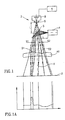
- Fig. 1 schematically illustrates a principal embodiment of an apparatus for optical inspection of an optical object A1 (only a portion of which is shown) for the existence of inhomogeneities and/or defects in its bulk or on its surfaces, such as for example defects D1 and D2.
- the inspected portion of the optical object A1 and the defects D1 and D2 are shown substantially exaggerated.
- the apparatus comprises illumination means 1 for the illumination of the optical object A1 with a diverging incident radiation beam, a projecting screen 2 on which the optical object A1 projects the incident radiation beam, imaging and detecting means 3 for the observation of the projected radiation and the detection thereof, and image processing means 4 for the analysis of the image.
- the apparatus also comprises a beam deflecting element 5 which directs the incident beam towards the inspected object A1 and which passes the imaging rays towards the imaging means 4.
- the illumination means 1 is in the form of a point source of radiation of any design providing suitable, preferably wide, divergence of radiation illuminating the optical object A1 along an optical axis X. It is desirable that the point source of radiation has minimal possible dimensions, whereby high resolution of measurements may be obtained and the inhomogeneities or defects distinguishable thereby may be very small.
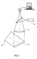
- Fig. 4 illustrates an apparatus according to the present invention, designed for the inspection of specular objects.
- the illumination means of the apparatus of Fig. 4 comprise a point source of radiation 40 providing a diverging illuminating beam and a positive lens 42 which transforms the diverging beam into a collimated beam for the illumination of an inspected optical object A4 having a reflective surface and producing a shadow pattern thereof on a projecting screen 44.
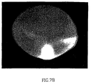
- Figs. 7a and 7b illustrate images of shadow patterns of a progressive lens
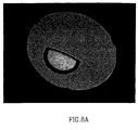
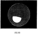
- Fig. 8a and 8b illustrate images of shadow patterns of a bifocal lens with its cylindrical power, obtained, respectively, by the method of the present invention and by conventional means.
- the shapes of the lenses as well as the shapes and the disposition of the defects therein are seen undistorted if compared with those obtained by conventional means (Figs. 7b and 8b).
Landscapes
- Physics & Mathematics (AREA)
- Health & Medical Sciences (AREA)
- Life Sciences & Earth Sciences (AREA)
- Chemical & Material Sciences (AREA)
- Analytical Chemistry (AREA)
- Biochemistry (AREA)
- General Health & Medical Sciences (AREA)
- General Physics & Mathematics (AREA)
- Immunology (AREA)
- Pathology (AREA)
- Investigating Materials By The Use Of Optical Means Adapted For Particular Applications (AREA)
- Testing Electric Properties And Detecting Electric Faults (AREA)
- Testing Of Optical Devices Or Fibers (AREA)
Claims (18)
- Verfahren zum Inspizieren eines optischen Gegenstands (A1, A2, A3, A4, A5, A6) auf das Vorhandensein von Ungleichmäßigkeiten darin, wobei das Verfahren folgendes aufweist:gekennzeichnet durch:Liefern eines Strahls von Inspizierungsstrahlung und Richten des Strahls auf den optischen Gegenstand (A1, A2, A3, A4, A5, A6), so dass Strahlen des Strahls mit einem einzigen Winkel auf jede beleuchtete Stelle einfallen;Projizieren des Strahls über den optischen Gegenstand (A1, A2, A3, A4, A5, A6) auf eine Projektionswand (2, 30, 44, 54, 64) und Erhalten eines Schattenmusters (52, 62) dabei, wobei die optischen Ungleichmäßigkeiten wegen des Unterschieds der Helligkeit der Gebiete, die ihm entsprechen, über der Hintergrundhelligkeit des Musters in den Schattenmustern (52, 62) unterschieden werden können;Abbilden des Schattenmusters (52, 62) über den optischen Gegenstand (A1, A2, A3, A4, A5, A6) in einer solchen Weise, dass die das Bild bildende Strahlen denselben optischen Weg wie die einfallenden Strahlen fortschreiten, durch jede beleuchtete Stelle des optischen Gegenstands (A1, A2, A3, A4, A5, A6) mit einem Winkel gehen, der dem Winkel entspricht, bei dem die Stelle beleuchtet ist; undAuffinden und Analysieren des Bilds des Schattenmusters.
- Verfahren nach Anspruch 1, in dem der auf den inspizierten optischen Gegenstand (A1, A2, A3, A5, A6) einfallende Strahl ein divergierender Strahl ist.
- Verfahren nach Anspruch 1, in dem der auf den inspizierten optischen Gegenstand (A4) einfallende Strahl ein kollimierter Strahl ist.
- Verfahren nach Anspruch 1, in dem der auf den inspizierten optischen Gegenstand einfallende Strahl ein konvergierender Strahl ist.
- Verfahren nach Anspruch 1, in dem der inspizierte optische Gegenstand (A4, A6) ein spiegelndes Element mit einer reflektierenden Oberfläche ist, wobei das Schattenmuster (62) durch die Strahlung hergestellt wird, die von der reflektierenden Oberfläche hergestellt wird und über sie abgebildet wird.
- Verfahren nach Anspruch 1, in dem der optische Gegenstand (A5) ein linear übersetztes Blattmaterial ist, das von einem Lichtstreifen beleuchtet wird, der quer zur Übersetzungsrichtung gerichtet ist, wobei das Bild von einem quer ausgerichteten Vielelementlinienauffindungsmittel (56) aufgefunden wird.
- Verfahren nach Anspruch 1, das zur automatisierten Qualitätskontrolle benutzt wird.
- Verfahren nach Anspruch 1, das zur Abbildung von optischen. Gegenständen benutzt wird, beruhend auf den örtlichen Messungen der optischen Kraft davon.
- Verfahren nach einem der Ansprüche 1 bis 8, in dem die Projektionswand (2) eine von diffundierenden, leuchtenden, phosphoreszierenden oder rückstreuenden Oberflächen ist.
- Vorrichtung zur Inspizierung eines optischen Gegenstands (A1, A2, A3, A4, A5, A6) auf das Vorhandensein von Ungleichmäßigkeiten darin, die folgendes aufweist:dadurch gekennzeichnet, dass die Vorrichtung weiterhin folgendes aufweist:ein Beleuchtungsmittel (1, 10, 10', 31, 40, 60) zum Liefern eines Strahls von Inspizierungsstrahlung und zur Beleuchtung des optischen Gegenstands (A1, A2, A3, A4, A5, A6) durch den Strahl, so dass Strahlen davon mit einem einzigen Winkel auf jede beleuchtete Stelle der einfallenden Strahlung einfallen;eine Projektionswand (2, 30, 44, 54, 64), wobei das Beleuchtungsmittel mittels des optischen Gegenstands (A1, A2, A3, A4, A5, A6) ein Schattenmuster (52, 62) davon auf der Projektionswand (2, 30, 44, 54, 64) liefert;ein Abbildungsmittel (3, 22, 24, 56 64) zum Abbilden des Schattenmusters (52, 62) über den optischen Gegenstand (A1, A2, A3, A4, A5, A6), das in einer solchen Weise angeordnet ist, dass die das Bild bildende Strahlen entlang denselben optischen Weg wie die einfallenden Strahlen fortschreiten, durch jede beleuchtete Stelle des optischen Gegenstands (A1, A2, A3, A4, A5, A6) mit einem Winkel gehen, der dem Winkel entspricht, bei dem die Stelle beleuchtet ist; undein Bildauffindungsmittel und Bildverarbeitungsmittel (4) zum Analysieren des Bilds des Schattenmusters (52, 62) auf Ungleichmäßigkeiten.
- Vorrichtung nach Anspruch 10, in der eine Ausgangspupille (18, 32) des Beleuchtungsmittels und eine Eingangspupille des Abbildungsmittels von dem inspizierten Gegenstand optisch gleich beabstandet sind.
- Vorrichtung nach Anspruch 10, in der das Beleuchtungsmittel (1) eine punktförmige Strahlungsquelle (1) ist.
- Vorrichtung nach Anspruch 10, in der das Beleuchtungsmittel ein strahlspaltendes Element (5, 36) aufweist.
- Vorrichtung nach Anspruch 10, in der das Beleuchtungsmittel einen divergierenden, konvergierenden oder kollimierten Strahl der Inspizierungssstrahlung vorsehen kann.
- Vorrichtung nach Anspruch 10, in der das Bildauffindungsmittel ein Vielelementauffindungsmittel ist, das die Hellingkeitsverteilung in dem Bild des Schattenmusters messen kann.
- Vorrichtung nach Anspruch 10, die weiterhin optische Elemente zur Berichtigung der Form des Schattenmusters aufweist.
- Vorrichtung nach Anspruch 10, in der der optische Gegenstand (A5) ein linear übersetztes Blattmaterial ist, wobei das Beleuchtungsmittel das Material mit einem Strahlungsstreifen beleuchten kann, der quer zu der Richtung der Übersetzung ausgerichtet ist, und das Bildauffindungsmittel ein Vielelementlinienauffindungsmittel ist.
- Vorrichtung nach einem der Ansprüche 10 bis 17, in der die Projektionswand (2) eine von diffundierenden, leuchtenden, phosphoreszierenden, oder rückstreuenden Oberflächen ist.
Applications Claiming Priority (2)
| Application Number | Priority Date | Filing Date | Title |
|---|---|---|---|
| IL11985096A IL119850A (en) | 1996-12-17 | 1996-12-17 | Optical method and apparatus for detecting low frequency defects |
| IL11985096 | 1996-12-17 |
Publications (3)
| Publication Number | Publication Date |
|---|---|
| EP0856728A2 EP0856728A2 (de) | 1998-08-05 |
| EP0856728A3 EP0856728A3 (de) | 1998-09-09 |
| EP0856728B1 true EP0856728B1 (de) | 2002-07-31 |
Family
ID=11069591
Family Applications (1)
| Application Number | Title | Priority Date | Filing Date |
|---|---|---|---|
| EP97308168A Expired - Lifetime EP0856728B1 (de) | 1996-12-17 | 1997-10-15 | Optisches Verfahren und Vorrichtung zum Erkennen von Fehlstellen |
Country Status (6)
| Country | Link |
|---|---|
| US (1) | US6075591A (de) |
| EP (1) | EP0856728B1 (de) |
| AT (1) | ATE221650T1 (de) |
| DE (1) | DE69714401T2 (de) |
| ES (1) | ES2180901T3 (de) |
| IL (1) | IL119850A (de) |
Families Citing this family (27)
| Publication number | Priority date | Publication date | Assignee | Title |
|---|---|---|---|---|
| FR2807522B1 (fr) * | 2000-04-07 | 2002-06-14 | Aerospatiale Matra Airbus | Dispositif pour determiner les valeurs d'au moins un parametre de particules, notamment de gouttelettes d'eau |
| US6671039B2 (en) * | 2000-06-22 | 2003-12-30 | Hoya Corporation | Spectacle lens image sensing processing apparatus and spectacle lens positioning method |
| US6661506B2 (en) * | 2000-08-24 | 2003-12-09 | Og Technologies, Inc. | Engine bearing inspection system |
| US7023542B2 (en) * | 2002-04-03 | 2006-04-04 | 3M Innovative Properties Company | Imaging method and apparatus |
| US7142295B2 (en) * | 2003-03-05 | 2006-11-28 | Corning Incorporated | Inspection of transparent substrates for defects |
| GB0307345D0 (en) * | 2003-03-29 | 2003-05-07 | Pilkington Plc | Glazing inspection |
| US7295330B2 (en) * | 2003-07-11 | 2007-11-13 | Chow Peter P | Film mapping system |
| US7715023B2 (en) | 2004-03-31 | 2010-05-11 | Kabushiki Kaisha Topcon | Jig mounting apparatus |
| EP1605241A1 (de) | 2004-06-09 | 2005-12-14 | Automation & Robotics | Apparat zur optischen Kontrolle von transparenten oder reflektierenden Proben |
| US20090174554A1 (en) | 2005-05-11 | 2009-07-09 | Eric Bergeron | Method and system for screening luggage items, cargo containers or persons |
| US7991242B2 (en) | 2005-05-11 | 2011-08-02 | Optosecurity Inc. | Apparatus, method and system for screening receptacles and persons, having image distortion correction functionality |
| US7899232B2 (en) | 2006-05-11 | 2011-03-01 | Optosecurity Inc. | Method and apparatus for providing threat image projection (TIP) in a luggage screening system, and luggage screening system implementing same |
| US8494210B2 (en) | 2007-03-30 | 2013-07-23 | Optosecurity Inc. | User interface for use in security screening providing image enhancement capabilities and apparatus for implementing same |
| DE102006051538B4 (de) * | 2006-10-27 | 2009-04-09 | Schott Ag | Verfahren und Vorrichtung zur Bestimmung der Waviness von Glasscheiben |
| JP4970149B2 (ja) * | 2007-05-31 | 2012-07-04 | 株式会社ニデック | カップ取付け装置 |
| US20110193954A1 (en) * | 2010-02-08 | 2011-08-11 | Sunrise Optical Llc | Apparatus for the measurement of the topography and photoelectric properties of transparent surfaces |
| JP2012243805A (ja) * | 2011-05-16 | 2012-12-10 | Toshiba Corp | パターン形成方法 |
| DE102011078833A1 (de) * | 2011-07-07 | 2013-01-10 | 3D-Micromac Ag | Verfahren und Vorrichtung zum Detektieren einer Markierung an einem Objekt |
| ES2675308T3 (es) | 2011-09-07 | 2018-07-10 | Rapiscan Systems, Inc. | Sistema de inspección de rayos X que integra datos de manifiesto con procesamiento de obtención de imágenes/detección |
| DE102011119806B4 (de) * | 2011-11-25 | 2020-10-15 | Carl Zeiss Vision International Gmbh | Verfahren und Vorrichtung zum Sichtbarmachen eines Signierzeichens auf einem Brillenglas |
| FR3017963B1 (fr) | 2014-02-27 | 2016-03-25 | Essilor Int | Instrument optique pour identifier et localiser des microgravures presentes sur une lentille ophtalmique |
| FR3017964B1 (fr) | 2014-02-27 | 2016-03-25 | Essilor Int | Instrument optique pour reperer au moins un point caracteristique d'une lentille ophtalmique |
| DE102015115735B3 (de) * | 2015-09-17 | 2017-03-23 | Carl Zeiss Vision International Gmbh | Vorrichtung und Verfahren zum Sichtbarmachen eines Signierzeichens auf einem Brillenglas |
| MY194719A (en) * | 2016-02-05 | 2022-12-15 | Toray Industries | Inspection device for sheet object, and inspection method for sheet object |
| EP3772702A3 (de) | 2016-02-22 | 2021-05-19 | Rapiscan Systems, Inc. | Verfahren zur verarbeitung radiographischer bilder |
| DE102024129287A1 (de) | 2024-10-10 | 2026-04-16 | Carl Zeiss Jena Gmbh | Inspektionsverfahren und inspektionssystem zum prüfen auf phasenverschiebende defekte und herstellungsverfahren |
| DE102024129286A1 (de) | 2024-10-10 | 2026-04-16 | Carl Zeiss Jena Gmbh | Inspektionsverfahren, herstellungsverfahren und inspektionssystem |
Family Cites Families (11)
| Publication number | Priority date | Publication date | Assignee | Title |
|---|---|---|---|---|
| US3743431A (en) * | 1972-05-09 | 1973-07-03 | Philco Ford Corp | Radiation sensitive means for detecting flaws in glass |
| GB1403911A (en) * | 1972-07-26 | 1975-08-28 | Sira Institute | Method and apparatus for testing optical components |
| IL63264A (en) * | 1980-11-04 | 1986-07-31 | Israel Atomic Energy Comm | Topographical mapping system and method |
| US4547073A (en) * | 1981-02-17 | 1985-10-15 | Matsushita Electric Industrial Co., Ltd. | Surface examining apparatus and method |
| DE3237511A1 (de) * | 1982-10-09 | 1984-04-12 | Fraunhofer-Gesellschaft zur Förderung der angewandten Forschung e.V., 8000 München | Verfahren zur pruefung von glaserzeugnissen |
| DE3406066A1 (de) * | 1984-02-20 | 1985-08-22 | Siemens AG, 1000 Berlin und 8000 München | Anordnung zur optischen erfassung raeumlicher unebenheiten in der struktur eines zu untersuchenden objekts |
| US4810895A (en) * | 1987-01-13 | 1989-03-07 | Rotlex Optics Ltd. | Method and apparatus for optical examination of an object particularly by moire ray deflection mapping |
| DE3816392A1 (de) * | 1988-05-13 | 1989-11-23 | Ver Glaswerke Gmbh | Verfahren zur bestimmung der optischen qualitaet von flachglas oder flachglasprodukten |
| DE3838954A1 (de) * | 1988-11-17 | 1990-05-23 | Siemens Ag | Optikanordnung zur dreidimensionalen formerfassung |
| DE3926349A1 (de) * | 1989-08-09 | 1991-02-14 | Sick Optik Elektronik Erwin | Optische fehlerinspektionsvorrichtung |
| US5309222A (en) * | 1991-07-16 | 1994-05-03 | Mitsubishi Denki Kabushiki Kaisha | Surface undulation inspection apparatus |
-
1996
- 1996-12-17 IL IL11985096A patent/IL119850A/xx not_active IP Right Cessation
-
1997
- 1997-10-15 DE DE69714401T patent/DE69714401T2/de not_active Expired - Fee Related
- 1997-10-15 ES ES97308168T patent/ES2180901T3/es not_active Expired - Lifetime
- 1997-10-15 EP EP97308168A patent/EP0856728B1/de not_active Expired - Lifetime
- 1997-10-15 AT AT97308168T patent/ATE221650T1/de not_active IP Right Cessation
- 1997-10-21 US US08/967,305 patent/US6075591A/en not_active Expired - Fee Related
Also Published As
| Publication number | Publication date |
|---|---|
| US6075591A (en) | 2000-06-13 |
| EP0856728A2 (de) | 1998-08-05 |
| IL119850A0 (en) | 1997-03-18 |
| DE69714401D1 (de) | 2002-09-05 |
| DE69714401T2 (de) | 2003-09-18 |
| ATE221650T1 (de) | 2002-08-15 |
| ES2180901T3 (es) | 2003-02-16 |
| EP0856728A3 (de) | 1998-09-09 |
| IL119850A (en) | 2000-11-21 |
Similar Documents
| Publication | Publication Date | Title |
|---|---|---|
| US6075591A (en) | Optical method and apparatus for detecting low frequency defects | |
| US5153668A (en) | Optical inspection apparatus and illumination system particularly useful therein | |
| US5125741A (en) | Method and apparatus for inspecting surface conditions | |
| EP1049925B1 (de) | Vorrichtung und verfahren zur optischen inspektion | |
| US4966457A (en) | Inspecting apparatus for determining presence and location of foreign particles on reticles or pellicles | |
| US4845558A (en) | Method and apparatus for detecting defects in repeated microminiature patterns | |
| US20010030744A1 (en) | Method of simultaneously applying multiple illumination schemes for simultaneous image acquisition in an imaging system | |
| US5659390A (en) | Method and apparatus for detecting particles on a surface of a semiconductor wafer having repetitive patterns | |
| US5128550A (en) | Method of and an apparatus for testing large area panes for optical quality | |
| JPS6182147A (ja) | 表面検査方法及び装置 | |
| JPS63261144A (ja) | 光学的ウエブモニター装置 | |
| JP3105702B2 (ja) | 光学式欠陥検査装置 | |
| JP3417736B2 (ja) | 光学部材検査装置 | |
| US8514385B2 (en) | Device and method for inspecting an object | |
| US5440383A (en) | Phase detection deflectometer-type optical device having a large measuring range | |
| GB2135448A (en) | Inspection apparatus and method | |
| JPH08166514A (ja) | 斜光照明装置 | |
| WO1996007076A1 (en) | Integral field lens illumination for video inspection | |
| US20030020916A1 (en) | Optical detection device | |
| JPH09105724A (ja) | 表面検査装置 | |
| JPH0961370A (ja) | 微分干渉顕微鏡及び該顕微鏡を使った欠陥検査装置 | |
| JPS6313446Y2 (de) | ||
| KR940002504B1 (ko) | 가는선의 미세결함 검출장치 | |
| JP2000295639A (ja) | 固体撮像素子検査用照明装置及びそれに用いる調整工具 | |
| CN121633113B (zh) | 一种检测设备的调试方法 |
Legal Events
| Date | Code | Title | Description |
|---|---|---|---|
| PUAI | Public reference made under article 153(3) epc to a published international application that has entered the european phase |
Free format text: ORIGINAL CODE: 0009012 |
|
| PUAL | Search report despatched |
Free format text: ORIGINAL CODE: 0009013 |
|
| AK | Designated contracting states |
Kind code of ref document: A2 Designated state(s): AT CH DE DK ES FR GB IE IT LI NL PT SE |
|
| AK | Designated contracting states |
Kind code of ref document: A3 Designated state(s): AT BE CH DE DK ES FI FR GB GR IE IT LI LU MC NL PT SE |
|
| 17P | Request for examination filed |
Effective date: 19990309 |
|
| AKX | Designation fees paid |
Free format text: AT CH DE DK ES FR GB IE IT LI NL PT SE |
|
| RBV | Designated contracting states (corrected) |
Designated state(s): AT CH DE DK ES FR GB IE IT LI NL PT SE |
|
| 17Q | First examination report despatched |
Effective date: 20001013 |
|
| GRAG | Despatch of communication of intention to grant |
Free format text: ORIGINAL CODE: EPIDOS AGRA |
|
| GRAG | Despatch of communication of intention to grant |
Free format text: ORIGINAL CODE: EPIDOS AGRA |
|
| GRAH | Despatch of communication of intention to grant a patent |
Free format text: ORIGINAL CODE: EPIDOS IGRA |
|
| GRAH | Despatch of communication of intention to grant a patent |
Free format text: ORIGINAL CODE: EPIDOS IGRA |
|
| GRAA | (expected) grant |
Free format text: ORIGINAL CODE: 0009210 |
|
| AK | Designated contracting states |
Kind code of ref document: B1 Designated state(s): AT CH DE DK ES FR GB IE IT LI NL PT SE |
|
| PG25 | Lapsed in a contracting state [announced via postgrant information from national office to epo] |
Ref country code: LI Free format text: LAPSE BECAUSE OF FAILURE TO SUBMIT A TRANSLATION OF THE DESCRIPTION OR TO PAY THE FEE WITHIN THE PRESCRIBED TIME-LIMIT Effective date: 20020731 Ref country code: CH Free format text: LAPSE BECAUSE OF FAILURE TO SUBMIT A TRANSLATION OF THE DESCRIPTION OR TO PAY THE FEE WITHIN THE PRESCRIBED TIME-LIMIT Effective date: 20020731 |
|
| REF | Corresponds to: |
Ref document number: 221650 Country of ref document: AT Date of ref document: 20020815 Kind code of ref document: T |
|
| REG | Reference to a national code |
Ref country code: GB Ref legal event code: FG4D Ref country code: CH Ref legal event code: EP |
|
| REG | Reference to a national code |
Ref country code: IE Ref legal event code: FG4D |
|
| REF | Corresponds to: |
Ref document number: 69714401 Country of ref document: DE Date of ref document: 20020905 |
|
| PG25 | Lapsed in a contracting state [announced via postgrant information from national office to epo] |
Ref country code: IE Free format text: LAPSE BECAUSE OF NON-PAYMENT OF DUE FEES Effective date: 20021015 |
|
| PG25 | Lapsed in a contracting state [announced via postgrant information from national office to epo] |
Ref country code: SE Free format text: LAPSE BECAUSE OF FAILURE TO SUBMIT A TRANSLATION OF THE DESCRIPTION OR TO PAY THE FEE WITHIN THE PRESCRIBED TIME-LIMIT Effective date: 20021031 Ref country code: DK Free format text: LAPSE BECAUSE OF FAILURE TO SUBMIT A TRANSLATION OF THE DESCRIPTION OR TO PAY THE FEE WITHIN THE PRESCRIBED TIME-LIMIT Effective date: 20021031 |
|
| PG25 | Lapsed in a contracting state [announced via postgrant information from national office to epo] |
Ref country code: PT Free format text: LAPSE BECAUSE OF FAILURE TO SUBMIT A TRANSLATION OF THE DESCRIPTION OR TO PAY THE FEE WITHIN THE PRESCRIBED TIME-LIMIT Effective date: 20021114 |
|
| ET | Fr: translation filed | ||
| REG | Reference to a national code |
Ref country code: CH Ref legal event code: PL |
|
| REG | Reference to a national code |
Ref country code: ES Ref legal event code: FG2A Ref document number: 2180901 Country of ref document: ES Kind code of ref document: T3 |
|
| PLBE | No opposition filed within time limit |
Free format text: ORIGINAL CODE: 0009261 |
|
| 26N | No opposition filed |
Effective date: 20030506 |
|
| REG | Reference to a national code |
Ref country code: IE Ref legal event code: MM4A |
|
| PGFP | Annual fee paid to national office [announced via postgrant information from national office to epo] |
Ref country code: GB Payment date: 20041029 Year of fee payment: 8 Ref country code: FR Payment date: 20041029 Year of fee payment: 8 |
|
| PGFP | Annual fee paid to national office [announced via postgrant information from national office to epo] |
Ref country code: AT Payment date: 20041031 Year of fee payment: 8 |
|
| PGFP | Annual fee paid to national office [announced via postgrant information from national office to epo] |
Ref country code: ES Payment date: 20041117 Year of fee payment: 8 |
|
| PGFP | Annual fee paid to national office [announced via postgrant information from national office to epo] |
Ref country code: DE Payment date: 20041223 Year of fee payment: 8 |
|
| PGFP | Annual fee paid to national office [announced via postgrant information from national office to epo] |
Ref country code: NL Payment date: 20041229 Year of fee payment: 9 |
|
| PG25 | Lapsed in a contracting state [announced via postgrant information from national office to epo] |
Ref country code: IT Free format text: LAPSE BECAUSE OF NON-PAYMENT OF DUE FEES Effective date: 20051015 Ref country code: AT Free format text: LAPSE BECAUSE OF NON-PAYMENT OF DUE FEES Effective date: 20051015 |
|
| PG25 | Lapsed in a contracting state [announced via postgrant information from national office to epo] |
Ref country code: ES Free format text: LAPSE BECAUSE OF NON-PAYMENT OF DUE FEES Effective date: 20051017 |
|
| PG25 | Lapsed in a contracting state [announced via postgrant information from national office to epo] |
Ref country code: DE Free format text: LAPSE BECAUSE OF NON-PAYMENT OF DUE FEES Effective date: 20060503 |
|
| GBPC | Gb: european patent ceased through non-payment of renewal fee |
Effective date: 20051015 |
|
| PG25 | Lapsed in a contracting state [announced via postgrant information from national office to epo] |
Ref country code: FR Free format text: LAPSE BECAUSE OF NON-PAYMENT OF DUE FEES Effective date: 20060630 |
|
| REG | Reference to a national code |
Ref country code: FR Ref legal event code: ST Effective date: 20060630 |
|
| REG | Reference to a national code |
Ref country code: ES Ref legal event code: FD2A Effective date: 20051017 |
|
| PG25 | Lapsed in a contracting state [announced via postgrant information from national office to epo] |
Ref country code: NL Free format text: LAPSE BECAUSE OF NON-PAYMENT OF DUE FEES Effective date: 20070501 |
|
| NLV4 | Nl: lapsed or anulled due to non-payment of the annual fee |
Effective date: 20070501 |