EP0856790A2 - Klient-Server-Netzwerkrechnersystem und -verfahren - Google Patents
Klient-Server-Netzwerkrechnersystem und -verfahren Download PDFInfo
- Publication number
- EP0856790A2 EP0856790A2 EP97309378A EP97309378A EP0856790A2 EP 0856790 A2 EP0856790 A2 EP 0856790A2 EP 97309378 A EP97309378 A EP 97309378A EP 97309378 A EP97309378 A EP 97309378A EP 0856790 A2 EP0856790 A2 EP 0856790A2
- Authority
- EP
- European Patent Office
- Prior art keywords
- server
- client
- information
- network
- link
- Prior art date
- Legal status (The legal status is an assumption and is not a legal conclusion. Google has not performed a legal analysis and makes no representation as to the accuracy of the status listed.)
- Granted
Links
Images


Classifications
-
- G—PHYSICS
- G06—COMPUTING OR CALCULATING; COUNTING
- G06F—ELECTRIC DIGITAL DATA PROCESSING
- G06F9/00—Arrangements for program control, e.g. control units
- G06F9/06—Arrangements for program control, e.g. control units using stored programs, i.e. using an internal store of processing equipment to receive or retain programs
- G06F9/46—Multiprogramming arrangements
- G06F9/465—Distributed object oriented systems
-
- H—ELECTRICITY
- H04—ELECTRIC COMMUNICATION TECHNIQUE
- H04L—TRANSMISSION OF DIGITAL INFORMATION, e.g. TELEGRAPHIC COMMUNICATION
- H04L67/00—Network arrangements or protocols for supporting network services or applications
- H04L67/01—Protocols
- H04L67/10—Protocols in which an application is distributed across nodes in the network
- H04L67/1001—Protocols in which an application is distributed across nodes in the network for accessing one among a plurality of replicated servers
-
- H—ELECTRICITY
- H04—ELECTRIC COMMUNICATION TECHNIQUE
- H04L—TRANSMISSION OF DIGITAL INFORMATION, e.g. TELEGRAPHIC COMMUNICATION
- H04L9/00—Cryptographic mechanisms or cryptographic arrangements for secret or secure communications; Network security protocols
- H04L9/40—Network security protocols
-
- H—ELECTRICITY
- H04—ELECTRIC COMMUNICATION TECHNIQUE
- H04L—TRANSMISSION OF DIGITAL INFORMATION, e.g. TELEGRAPHIC COMMUNICATION
- H04L67/00—Network arrangements or protocols for supporting network services or applications
- H04L67/01—Protocols
Definitions
- the present invention relates to a network computing system for updating and adding data in a distributed client-server system through a network, and its method.
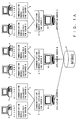
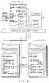
- Fig.1A is a block diagram of the conventional client-server system.
- the system in Fig.1A comprises clients 1, application servers 5 (application servers A, B and C) and a database 6.
- the application servers A, B and C share the database 6 among them, and are provided with a server A exclusive communication module 2, a server B exclusive communication module 3 and a server C exclusive communication module 4 respectively, in order to communicate with the clients 1.
- a client 1 is provided with (linked to) the server A exclusive communication module 2, the server B exclusive communication module 3, or the server C exclusive communication module 4, and updates the database 6, etc. connected to a specific application server 5 having a corresponding communication module.
- each of the application servers A, B and C manages an individual database 6. Also in this system, the clients 1 are connected only to specific application servers 5 using one of the server A exclusive communication module 2, the server B exclusive communication module 3, and the server C exclusive communication module 4.
- a client 1 accesses the data in the database 6 of a server 5 different from the application server 5 of the connected party
- replication of data is made between the relevant databases 6, or a remote procedure call (RPC) is made between the application servers 5.
- RPC remote procedure call
- data is copied between different databases 6, and in the case of an RPC, a function call is made and the necessary data are exchanged between the application servers 5.
- a client 1 is designed to be connected with a specific application server 5 by using communication modules 2, 3 and 4.
- WWW World Wide Web
- HTML hypertext transfer protocol
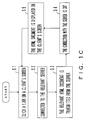
- Fig.1C is a flowchart showing the operation of a client and a server on the WWW.
- the client starts operating and the user clicks a link on the screen (step S1)
- the client is connected to the corresponding server using the HTTP (step S2).
- the corresponding HTML document is sent from the server to the client (step S3), and the connection with the server is cut (step S4) and the data of the HTML document is displayed on the screen (step S5).
- step S3 the connection with the server is cut
- step S5 the data of the HTML document is displayed on the screen.
- the server 5 of the connected party of the client 1 has to be connected with another server 5 and has to ask for a necessary process, which generates many transactions between the servers 5.
- this process becomes complicated in the same way.
- the conventional WWW also has a problem that it is provided with only a simple function of sending an HTML document on a client's request. Particularly, since its session is cut after every transmission of one page in HTTP, the communicating state (connecting state) cannot be held. Accordingly, it is difficult to develop a client-server system for performing a real interaction only with the basic functions of the WWW.
- the network computing system of the present invention manages distributed data in a distributed system through a communication network.
- a client side is provided with a common communication unit and a connection management unit.
- the common communication unit controls the communication between a client and a plurality of servers on the network and can access the plurality of servers commonly.
- the connection management unit connects the client to the second server out of the plurality of servers, if necessary, while holding the connecting state of the client with the first server, and enables the client to receive services from the second server.
- the common communication unit is not for communicating with a specific server as it is conventionally, and it can communicate with all the servers on the network commonly. For example, it is assumed that it has become necessary to ask the second server for a process when a client is connected to the first server under the control of the common connection unit. In this case the client is connected to the second server under the control of the connection management unit while it is still connected with the first server, and the client receives services from the second server.
- a server side is also provided with a common communication unit and a connection management unit.
- the common communication unit controls the communication between the first server and a client on the network, and receives an access from the client.
- the connection management unit connects the client to the second server, if necessary, while it holds the connecting state of the client with the first server, and sends out link information for receiving services from the second server to the client.
- the common communication unit does not correspond exclusively to each server as is conventional, but is common to all the servers on the network. For example, it is assumed that it has become necessary to ask the second server for a process when a client is connected to the first server under the control of the common connection unit. In this case, link information for accessing the second server is sent to the client under the control of the connection management unit. The client is connected to the second server using the received link information while it is still connected with the first server, and the client receives services from the second server.
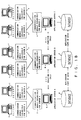
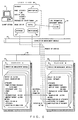
- Fig.2A is a drawing showing the principle of the network computing system of the present invention.
- the network computing system in Fig.2A manages distributed data in a distributed system through a communication network.
- a client side is provided with a common communication unit 11 and a connection management unit 12.
- the common communication unit 11 controls the communication between a client and a plurality of servers on the network, and can access the plurality of servers commonly.
- the connection management unit 12 connects the client to the second server out of the plurality of servers while it is connected with the first server, and enables the client to receive services from the second server.
- the common communication unit 11 is not for communication with a specific server as it is conventionally, but can communicate with all the servers on the network commonly. For example, it is assumed that it has become necessary to ask the second server for a process when a client is connected to the first server under the control of the common communication unit 11. In this case the client is connected to the second server under the control of the connection management unit 12 while it is still connected with the first server, and receives services from the second server.
- the client is connected to a required server not through a specific server, but directly, and can receive services such as information providing, etc.
- the request for the processing between servers accompanying the update and addition of data is also made automatically through the client.
- a server side is also provided with a common communication unit 13 and a connection management unit 14.
- the common communication unit 13 controls the communication between the first server and the client on the network, and receives the access from the client.
- the connection management unit 14 connects the client to the second server, if necessary, while it holds the connecting state with the first server of the client, and sends out link information for receiving services from the second server to the client.
- the common communication unit 13 does not correspond exclusively to each server as it does conventionally, but is common to all the servers on the network. For example, it is assumed that it has become necessary to ask the second server for a process when a client is connected to the first server under the control of the common connection unit 13. In this case, link information for accessing the second server is sent to the client under the control of the connection management unit 14. The client is connected to the second server while it is still connected with the first server, and the client receives services from the second server.
- the client can access any server on the network and receive services such as information providing, etc. by receiving link information representing a link to the next server from the connected server.
- the request for the processing between servers accompanying the update and addition of data is also made automatically through the client.
- the common communication units 11 and 13 in Fig.2A correspond to the common communication modules 22 of a client 21 and a server 23 in Fig.2B, respectively.
- the connection management units 12 and 14 correspond to the connection management modules 41 of a client 21 and a server 23 in Fig.4, respectively.
- Fig.2B is a block diagram showing the basic architecture of the network computing system of this embodiment.
- each client 21 and each application server 23 are united by a communication network 25 such as LAN, etc. and include a common communication module 22.
- Each server 23 manages each individual database 24.
- a client 21 may be connected to any server 23 using the common communication module 22.
- the client 21 uses the function of each server 23 and accesses the data of each database 24, basically there is no need for communication between the servers 23 and the replication of data between databases 24.
- a common communication module 22 can be down-loaded to the client 21 using a JAVA (trade mark) applet.
- JAVA is a network-oriented program language of an interpreter base, and a JAVA applet means a program coded in JAVA.
- the JAVA applet can be run in any operating system (OS). For example, it can be down-loaded from the server 23 and run in the client 21.
- OS operating system
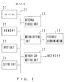
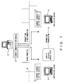
- Fig.3 is a block diagram of the information processing apparatus used as a client 21 or a server 23.
- the information processing apparatus in Fig.3 is provided with a central processing unit (CPU) 31, a memory 32, an input unit 33, an output unit 34, an external storage unit 35, a media driving unit 36 and a network connecting unit 37, and they are connected with each other by means of a bus 38.
- CPU central processing unit
- the CPU 31 executes programs stored in the memory 32, and realizes each process of the client 21 and server 23.
- the memory 32 for example, a read only memory (ROM), random access memory (RAM), etc. are used.
- the input unit 33 takes the form of, for example, a keyboard, pointing device, etc., and is used to input instructions from a user.
- the output unit 34 takes the form of a display device, printer, etc., and is used to display views to be presented to users and to output information in other formats.
- the external storage unit 35 is, for example, a magnetic disk device, optical disk device, magneto-optical disk device, etc., and can store programs and data. It can be also used as a database 24.
- the media driving unit 36 drives a portable recording medium 39, and accesses its memory contents.
- a portable recording medium 39 an arbitrary recording medium which can be read by a computer such as a memory card, floppy disk, compact disk read only memory (CD-ROM), optical disk, magneto-optical disk, etc. can be used.
- This portable recording medium 39 also stores the programs for the processes of the client 21 and server 23 besides data.
- the network connecting unit 37 is connected to a network 25 shown in Fig. 2B, and performs data conversions accompanying communication.
- the client 21 and server 23 can receive necessary information from the network 25 through the network connecting unit 37.
- An object means a unit of information in an object-oriented database, and is a combination of data and a method, which is a procedure applied to the data. By executing the method defined in the object various kinds of data processing can be realized.
- Fig.4 shows the state in which the client 21 is connected to a server 23.
- the connection management modules 41 of the client 21, and servers A and B in Fig. 4 are included in the common communication module 22 in Fig.2B.
- the link information management module 42 can also be included in the common communication module 22.
- a client 21 is connected to a server A, and information on an object 44 in the server A is displayed on the screen of the client 21 as a user view 43.
- the logical ID of the object 44 is "A//001", which represents that the object ID in the server A is "001".
- the class to which the object 44 belongs is "organization”, and its attributes are defined as an organization name of "software research department”, a department code of "1111” and a phone No. of "2222".
- the logical ID "B//001" of an object 45 of another server B and the logical ID "C//002" of an object (not shown in the drawing) of a server C are defined.
- a link which each object holds can be set not only between objects in the same server 23, but also between objects in the different servers 23.
- this link information is sent from the server 23 to the link information management module 42 of the client 21 through a connection management module 41.
- the work flow represents the operation of a work flow tool, i.e. a software for standardizing works in the organization, and here it represents the preparation work of "monthly report" by a user.
- the link information management module 42 stores a link "B//001" to a research plan document and a link "C//002" to a monthly report document, related to detail buttons 48 and 49 on the user view 43, respectively.
- this user view 43 By a user's operation on this user view 43 the method of the object 44 in a server A can be executed, or the linked objects in other servers B and C are automatically accessed.
- the work flow tool can be in the server A or another server 23.
- the connection management module 41 of the server B searches a pointer to the object 45 from the logical ID "B//001", and establishes a connection with the client 21. After the connection is established, the display data/ link information relating to the object 45 are transmitted to the client 21.
- the user view 43 is modified as shown in Fig.6.
- "document” representing the class of the object 45
- "research plan” representing its name
- "December 10, 1996” representing its date of issue
- "Ichiro Tanaka” representing its issuer
- the link information management module 42 holds the logical ID of the object 44 representing the organization to which the object 45 belongs, as a link related to the detail button 54, the organization to which it belongs.
- a connecting state means the communicating state in which an execute request of a method and the executed result of the method can be exchanged between the objects in the servers A and B.
- the client 21 can receive services from the server B without communication between the servers A and B. This is because both communication modules 22 on the client 21 and server 23 sides are standardized.
- a current state means information on a processing state such as what view is currently opened on the client 21, etc.
- Fig.9 shows an example of the module configuration in a network computing system.
- the common communication module 22 and connection management module 41 described above are omitted, and a management server 61 is provided on the network 25 for managing other servers 23.
- the management server 61 is connected to a management server database 62 having directory information 66 and class definition information 67, and comprises a directory information management module 63, a class information management module 64 and a new server setting module 65.
- the directory information management module 63, the class information management module 64, and the new server setting module 65 manages directory information, manages class information and sets a new server, respectively.
- Each server 23 distributed on the network 25 comprises a link setting module 70, an object generating module 71, a replication module 72 and a service module 73.
- Each server database 24 comprises object information 68 and replication information 69.
- the object generating module 71 generates each object and stores it in a database 24 as object information 68.
- the link setting module 70 sets a link between objects distributed on the network 25 in the generated object information 68.
- the replication information 69, replication module 72 and service module 73 are described later.
- the client 21 comprises the above-described link information management module 42 and a view module 74 for displaying views on the screen, and refers to, generates and updates the object in a server 23 accessing it.
- Each module itself of a management server 61, a server 23 and a client 21 is managed as an object, and has its own data and method. Therefore, the function of each module can be realized by executing the method corresponding to it.
- the objects generated in a server 23 are managed by the directory information management module 63 in the management server 61 using directory information 66.
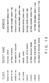
- the directory information 66 represents information on the location of each object on the network 25, for example, as shown in Fig.10, and holds a unique pair of the object name (or object ID) and object address for each class.
- an object address having an object name of "research center” is research center server//1001. This address corresponds to the logical ID of the object.
- a URL (Uniform Resource Locator) in the WWW, etc. can also be used as an object address.
- link information between objects is not managed as directory information 66.
- a class means a definition of the attribute of the object and its link with another object, and this information is held as class definition information 67.
- a class information management module 64 creates/updates the class definition information 67.
- the class name of an object "research center” in Fig.10 is "organization”.
- a link between an organization class and an individual class is defined. These links are internally managed using a unique name or ID. Any characteristic can be defined for each link. For example, information showing that it is an indispensable link, information showing that there can be a plurality of links, etc. can be set as its characteristic.
- a relation that there are N (N ⁇ 1) members in an organization or conversely that a certain individual belongs to an organization is defined for a link.
- the object for which a user does not want to designate a link like this can be handled as a special root class with no link.
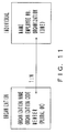
- a link can be defined for one direction only, in this embodiment, a bi-directional link can be also defined as shown in Fig.11.
- class definitions like this can also define a method.
- information on a link out of various kinds of class information plays a specially important role, and its attribute and method are the same as a general object.
- a hierarchical structure such as a corporate organization can be also managed.
- Fig.12 shows an example expressing models of corporate activities using class definitions.
- a link of "Located” is set between a location class 81 and a server class 82, and between a location class 81 and an organization/project class 83
- a link of "BelongTo” is set between a server class 82 and an organization/project class 83, between an organization/project class 83 and a document class 84, and between a document class 84 and an individual class 85, respectively.
- a link of "MemberOf" is set between an organization/project class 83 and an individual class 85, and a link of "PurposeOf” is set between an organization/project class 83 and a business function class 86.
- the business function class 86 includes several process classes 87, and a link of "Pre/Post” is set between process classes 87. Furthermore, a link of "Input/Output” is set between a process class 87 and a document class 84, and a link of "Charged” is set between a process class 87 and an individual class 85.
- a hierarchy can be defined as an internal structure, and a hierarchical structure can be defined between a plurality of process classes 87.
- a client 21 referring to the organization object 93 of "software research department” in the software research (software research department) server 91 has designated a link in order to refer to the information on a member "Yamada”.
- the client 21 is connected to the software development (software development department) server 92, in which an object of "Yamada” exists, by this link information, and the information of the object 94 of "Yamada” is displayed.
- the software research server 91 and the software development server 92 correspond to the servers 23.
- a server 23 can notify a client 21 of a method. In this manner, by automatically asking execution of a method between servers 23 through a client 21, a series of processes are performed transparently on the network. The request for the execution of a method for another server 23 can be realized by a method call using message transmission between objects.
- OMG object management group
- CORBA common object request broker architecture
- a user connected to a certain server 23 When a user connected to a certain server 23 generates a new object, he or she designates a class of an object to be generated and a server 23 for storing the object, and asks the object generating module 71 of the server 23 to process it.
- the user can also designate information on the link for the new object at the same time.
- the object generating module 71 can be made to ask the user to designate objects necessary to be linked, based on the class information of the generated object.
- the client 21 sends out object information including the link information to the server 23, and at the same time notifies a management server 61 of the registration of the new object. It also asks the objects to be linked to add link information.
- a new link with another object can also be set to the existing object.
- an organization object and a document object can be related as shown in Fig.12.
- a new document can be created and linked with the organization object.
- the deletion of an object can be also realized by the same procedures.
- Fig.14 shows the generating operation of a new object in the example of Fig.13.
- a client 21 accesses a software research server 91 and is displaying the information on the organization object 93 of "software research”.
- Fig.15 shows the user view at this time. The part underlined on the screen represents a link to another object, and by clicking on there the information on the corresponding object is displayed.
- connection management module 41 of the client 21 first obtains the link information to an object generating module 71 of "software development server//object generation" from the connection management module 41 of the software development server 92, and stores it in a link information management table in a link information management module 42.
- the client 21 asks the object generating module 71 of the connected software development server 92 to generate the individual object of a new member using the link information "software development server//object generation".
- the object generating module 71 generates the individual object 94 for a member "Yamada".
- the organization "Yamada” belongs to is defined as "software research”
- a link to the organization object 93 of "software research” is automatically set.
- the client 21 When starting an operation, the client 21 obtains link information "management server//directory information management" to the directory information management module 63 of a management server 61, and stores it in a link information management module 42. Therefore, the client 21 asks the management server 61 to add new directory information using this link information. Thus, an object 94 is registered in the directory information 66 of the management server 61 (management server database 62) as a new object.
- the client 21 also obtains a link information "software research server//software research" to the object 93 of the software research server 91 from the individual object 94, and asks the object 93 to add a link.
- a link to the individual object 94 of "Yamada” is set for the member item of the object 93, and a new member name of "Yamada” is displayed additionally on the screen of the object 93 of the "software research" of the client 21.
- the generation of a new object and the addition of the directory information and link accompanying it are realized as a client 21 led process.
- the addition of the directory information and link can be also performed in the form of a request from a software development server 92 to both the management server 61 and the software research server 91 through the client 21.
- the user When the user registers a new server 23, it asks a new server setting module 65 of the management server 61 to process it.
- the requested new server setting module 65 loads the new server 23 with the necessary modules such as a link setting module 70, object generating module 71, etc.
- an object of a server class 82 i.e., the special object class shown in Fig.12, is also generated.
- the server 23 is registered in the management server 61.
- IP internet protocol
- URL etc.
- service module 73 in Fig.9
- services provided by service module 73 in Fig.9 such as user management, retrieval, etc. are described below.
- the above-described individual object can be used for user management.
- the management server 61 When a new user is registered, it generates an individual object for user management, and stores its user information such as a password, etc. there. This individual object is managed by the management server 61, and when the user logs onto the system from another server 23 in which the individual object does not exist, the management server 61 accesses the object and performs user authorization, etc.
- the information of an object and a link can be also used for a log-in screen when the user logs onto the system.
- the links to organization/project, document and process are defined from the individual object. For this reason the link to the organization and project to which the user belongs, the document of the user and the assigned process, can be displayed on the log-in screen.
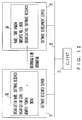
- Fig.16 shows an example of a log-in screen such as this.
- the user clicks "software research” and “browser development” or “server development” on this screen the information on the organization object 93 of "software research” and the information on the corresponding project object respectively are displayed.
- “department meeting material” or “development specifications” is clicked, the information on the corresponding document object is displayed.
- the service module 73 also provides retrieval services. Since a link among objects is configured as a relation between classes as shown in Fig.12, by tracing it such an object as to satisfy a certain condition can be retrieved. For example, by referring to the link between an organization/project class 83 and a document class 84 all "minutes" belonging to "software research" can be retrieved and displayed.
- retrieval tool of the conventional WWW system performs a round robin retrieval, retrieval takes a considerable time.
- intelligent retrieval based on a relation between classes is available, and retrieval can be processed efficiently.
- the directory management by the management server 61 itself can be also cancelled.
- the replication module 72 in Fig.9 replicates only information on the objects of a server class 82 between all servers 23.
- the replicated information on the class and object is stored in the database 24 of each server 23 as replication information 69.
- the information on the location of each server 23 on the network 25 is commonly shared by all servers 23.
- each object is made to have a link with the server object of the server 23 to which it belongs.
- each object can access all other objects through the server object.
- the same replication process is also available for each object, which can speed up the access to each object.
- a link is set between the master object to be copied and the replica (copy) of the object.
- the server When modification of the information on the replica is requested by the client 21, the server is automatically switched over and connected to a server 23 having the master object, and the master object is updated. Then, by the replication function, the modification of the master object is reflected in another object, that is, replica.
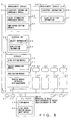
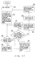
- Fig.17 ia a flowchart showing the general operation of the network computing system.
- a view module 74 asks an object in a server 23 to execute its method (step S12), if necessary.
- the logical ID of the requested object is retrieved by a link information management module 42.
- connection management module 41 of the client 21 judges whether or not it is connected to the requested server 23 by referring to the logical ID (step S13), and if not, it executes the connection process and notifies the client 21 of a request to execute its method (step S14).
- connection management module 41 of the server 23 retrieves the requested object according to the logical ID by referring to an object management table (step S15).
- the object management table has information for converting the logical ID of each object to an object pointer. For example, it is stored in the connection management module 41. In this way the retrieved object executes the requested method.
- step S16 it is checked if there is a request for executing a method of another object while executing the method (step S16), and if there is a request, it asks the client 21 being connected to execute the method (step S17). Thus, the operations in and after step S13 are repeated.
- step S18 When there is no request to execute another method while executing the method and the execution terminates, various kinds of notification and data transmission are executed for related clients 21 by the server 23 (step S18). At this time information on the objects modified/added by the method execution, etc. is sent to the client 21.
- the view module 74 of the client 21 modifies the view using the received information (step S19), and also modifies/adds the link information in a link information management module 42 (step S20), if necessary. Thus, when a new user interaction occurs on the modified screen (step S11), the operations in and after step S12 are repeated.
- Fig.18 is a flowchart showing the generation processing of a new object.
- a user instructs the generation of a new object as shown in Fig.14 on the view of a client 21 (step S21).
- the connection management module 41 of the client 21 does not have the address information on the server 23 in which the object should be stored, it obtains the address information from the server 23 being connected or a management server 61 (step S22).
- connection management module 41 sends out necessary information to the object generating module 71 of the server 23 in which the object should be stored, and asks it to execute an object storing method (step S23). Then, the object generating module 71 generates a new object including its link information, stores it in a database 24 and returns its logical ID to the client 21.
- the client 21 hands over the logical ID of the new object to another object having a link with the newly generated object and asks the execution of a link add method (step S24).
- the object having received this request adds the logical ID as a new link.
- the client 21 then asks the directory information management module 63 of the management server 61 to execute the register method of the new object (step S25), if necessary. Then, the directory information management module 63 adds the class name, object name, address information, etc. of the new object to a directory information 66, and a series of the processes finishes.
- a method call is made through a client by sending link information from a server side to a client side, if necessary. Therefore, the communication needed between servers can be performed under the lead of the client, which eliminates the conventional complicated communication control.
Landscapes
- Engineering & Computer Science (AREA)
- Theoretical Computer Science (AREA)
- Software Systems (AREA)
- Computer Networks & Wireless Communication (AREA)
- Signal Processing (AREA)
- General Engineering & Computer Science (AREA)
- Physics & Mathematics (AREA)
- General Physics & Mathematics (AREA)
- Computer Security & Cryptography (AREA)
- Computer And Data Communications (AREA)
- Information Transfer Between Computers (AREA)
- Multi Processors (AREA)
- Information Retrieval, Db Structures And Fs Structures Therefor (AREA)
Applications Claiming Priority (3)
| Application Number | Priority Date | Filing Date | Title |
|---|---|---|---|
| JP112781/97 | 1997-01-30 | ||
| JP11278197A JP3652834B2 (ja) | 1997-04-30 | 1997-04-30 | クライアント主導のネットワーク・コンピューティングシステムおよび方法 |
| JP11278197 | 1997-04-30 |
Publications (3)
| Publication Number | Publication Date |
|---|---|
| EP0856790A2 true EP0856790A2 (de) | 1998-08-05 |
| EP0856790A3 EP0856790A3 (de) | 2002-04-17 |
| EP0856790B1 EP0856790B1 (de) | 2005-01-26 |
Family
ID=14595348
Family Applications (1)
| Application Number | Title | Priority Date | Filing Date |
|---|---|---|---|
| EP97309378A Expired - Lifetime EP0856790B1 (de) | 1997-04-30 | 1997-11-20 | Client-Server-Netzwerkrechnersystem und -verfahren |
Country Status (3)
| Country | Link |
|---|---|
| US (1) | US6199111B1 (de) |
| EP (1) | EP0856790B1 (de) |
| JP (1) | JP3652834B2 (de) |
Families Citing this family (19)
| Publication number | Priority date | Publication date | Assignee | Title |
|---|---|---|---|---|
| JP2000285062A (ja) * | 1999-03-31 | 2000-10-13 | Ricoh Co Ltd | 業務用クライアントサーバシステム |
| US6615235B1 (en) * | 1999-07-22 | 2003-09-02 | International Business Machines Corporation | Method and apparatus for cache coordination for multiple address spaces |
| US6938256B2 (en) * | 2000-01-18 | 2005-08-30 | Galactic Computing Corporation | System for balance distribution of requests across multiple servers using dynamic metrics |
| JP2001216239A (ja) * | 2000-01-31 | 2001-08-10 | Toshiba Corp | ネットワーク通信システムおよびサーバ |
| US6859836B2 (en) * | 2000-03-29 | 2005-02-22 | Massoud Alibakhsh | System and method for providing look ahead socket generation |
| US7231436B1 (en) * | 2000-05-25 | 2007-06-12 | Microsoft Corporation | Object-based machine automation method and system |
| US10878178B2 (en) | 2000-06-07 | 2020-12-29 | Pt 291, Llc | Modifying web pages to be served by computer server system |
| US7996259B1 (en) | 2000-06-07 | 2011-08-09 | Perfect Web Technologies, Inc. | Method for developing electronic documents providing e-commerce tools |
| US6816905B1 (en) * | 2000-11-10 | 2004-11-09 | Galactic Computing Corporation Bvi/Bc | Method and system for providing dynamic hosted service management across disparate accounts/sites |
| US8538843B2 (en) | 2000-07-17 | 2013-09-17 | Galactic Computing Corporation Bvi/Bc | Method and system for operating an E-commerce service provider |
| GB2368411B (en) * | 2000-10-25 | 2004-01-28 | Proksim Software Inc | Sharing data over a network |
| US7240105B2 (en) * | 2001-01-26 | 2007-07-03 | International Business Machines Corporation | Distributed multicast caching technique |
| US20020138614A1 (en) * | 2001-03-20 | 2002-09-26 | Hall Dennis W. | Method and apparatus to manage network addresses |
| US6687733B2 (en) | 2001-06-01 | 2004-02-03 | Intergenix | Method and system for automatically configuring a client-server network |
| JP2003324448A (ja) * | 2002-05-02 | 2003-11-14 | Nobuo Hamazaki | オブジェクト管理システム、管理サーバおよびオブジェクト管理処理方法 |
| CN101040292A (zh) | 2004-10-13 | 2007-09-19 | 日生信息技术株式会社 | 数据管理装置及其方法 |
| MX2011000025A (es) * | 2008-07-28 | 2011-05-30 | Sony Corp | Dispositivo de cliente y metodologia asociada para acceder a servicios en red. |
| US9392066B2 (en) * | 2013-04-24 | 2016-07-12 | Cisco Technology, Inc. | Connection persistence across server farms in a network environment |
| JP6811947B2 (ja) * | 2015-10-22 | 2021-01-13 | 公立大学法人会津大学 | 災害時情報管理システム、これに用いるサーバ装置及び端末装置 |
Family Cites Families (18)
| Publication number | Priority date | Publication date | Assignee | Title |
|---|---|---|---|---|
| US5218699A (en) * | 1989-08-24 | 1993-06-08 | International Business Machines Corporation | Remote procedure calls in heterogeneous systems |
| JPH0778776B2 (ja) | 1991-09-24 | 1995-08-23 | インターナショナル・ビジネス・マシーンズ・コーポレイション | 分散資源部分のアクセス方法及びネットワーク |
| US5649192A (en) * | 1993-01-15 | 1997-07-15 | General Electric Company | Self-organized information storage system |
| JPH0887463A (ja) * | 1994-09-19 | 1996-04-02 | Nippon Telegr & Teleph Corp <Ntt> | 分散リソースリンク制御方法およびシステム |
| US5689645A (en) * | 1994-12-01 | 1997-11-18 | Hewlett-Packard Co. | Persistence specification system and method for producing persistent and transient submaps in a management station for a data communication network |
| US5758084A (en) * | 1995-02-27 | 1998-05-26 | Hewlett-Packard Company | Apparatus for parallel client/server communication having data structures which stored values indicative of connection state and advancing the connection state of established connections |
| JPH08235096A (ja) * | 1995-02-28 | 1996-09-13 | Nippon Telegr & Teleph Corp <Ntt> | プロセス間リンクコネクション設定システム及びその設定方法 |
| JP3463399B2 (ja) * | 1995-03-13 | 2003-11-05 | 富士通株式会社 | 通信システムおよびアクセス応答装置およびアクセス要求装置 |
| AU694367B2 (en) * | 1995-06-07 | 1998-07-16 | Soverain Software Llc | Internet server access control and monitoring systems |
| JP3613863B2 (ja) * | 1995-07-19 | 2005-01-26 | 株式会社日立製作所 | ネットワーク接続システム及び並列ネットワーク接続方法 |
| JP3734051B2 (ja) * | 1995-09-28 | 2006-01-11 | 日立ソフトウエアエンジニアリング株式会社 | ネットワーク管理システム |
| US5796934A (en) * | 1996-05-31 | 1998-08-18 | Oracle Corporation | Fault tolerant client server system |
| US5852724A (en) * | 1996-06-18 | 1998-12-22 | Veritas Software Corp. | System and method for "N" primary servers to fail over to "1" secondary server |
| US5835724A (en) * | 1996-07-03 | 1998-11-10 | Electronic Data Systems Corporation | System and method for communication information using the internet that receives and maintains information concerning the client and generates and conveys the session data to the client |
| US5867495A (en) * | 1996-11-18 | 1999-02-02 | Mci Communications Corporations | System, method and article of manufacture for communications utilizing calling, plans in a hybrid network |
| US5913061A (en) * | 1997-01-08 | 1999-06-15 | Crossroads Software, Inc. | Modular application collaboration |
| US5875296A (en) * | 1997-01-28 | 1999-02-23 | International Business Machines Corporation | Distributed file system web server user authentication with cookies |
| US6101508A (en) * | 1997-08-01 | 2000-08-08 | Hewlett-Packard Company | Clustered file management for network resources |
-
1997
- 1997-04-30 JP JP11278197A patent/JP3652834B2/ja not_active Expired - Fee Related
- 1997-11-18 US US08/972,363 patent/US6199111B1/en not_active Expired - Lifetime
- 1997-11-20 EP EP97309378A patent/EP0856790B1/de not_active Expired - Lifetime
Also Published As
| Publication number | Publication date |
|---|---|
| US6199111B1 (en) | 2001-03-06 |
| EP0856790A3 (de) | 2002-04-17 |
| EP0856790B1 (de) | 2005-01-26 |
| JP3652834B2 (ja) | 2005-05-25 |
| JPH10301911A (ja) | 1998-11-13 |
Similar Documents
| Publication | Publication Date | Title |
|---|---|---|
| EP0856790B1 (de) | Client-Server-Netzwerkrechnersystem und -verfahren | |
| Karasavvas et al. | Introduction to OGSA-DAI services | |
| US8914807B2 (en) | Method, system, and program for generating a program capable of invoking a flow of operations | |
| EP0648354B1 (de) | Verfahren und system für implementierung-unabhängige schnittstellenspezifikation | |
| EP1025507B1 (de) | Kombiniertes internet-und datenzugangssystem | |
| EP0786723B1 (de) | Dokumenten-Verwaltungssystem unter Verwendung von objekt- und agentorientierten Methoden | |
| AU2001295024B2 (en) | Developing applications online | |
| US6636875B1 (en) | System and method for synchronizing related data elements in disparate storage systems | |
| US5933604A (en) | Network resource monitoring system and method for providing notice of changes in resources in a network | |
| US6954751B2 (en) | Accessing data stored at an intermediary from a service | |
| WO2001025919A2 (en) | Architectures for netcentric computing systems | |
| US7827238B2 (en) | Exchanging data using programmatic conversion to emulated HTML form data | |
| JPH0954782A (ja) | ウェブ・ブラウザのリクエストを実行するためのサブエージェント・サービス・エージェント | |
| JP2006501558A (ja) | ウェブ・アプリケーション用のウェブ・ページのセッションをユーザに表示する装置と方法 | |
| EP1390861A2 (de) | Dienstbereitstellungssystem und -verfahren | |
| CA2435666A1 (en) | A method and a bridge for coupling a server and a client of different object types | |
| Ju et al. | An embedded Web server architecture for XML-based network management | |
| CN1333342C (zh) | 交换基础设施系统和方法 | |
| EP1368751A2 (de) | Datenbankintegrität in einer internetumgebung für elektronischen handel | |
| CN100461174C (zh) | 用于动态地创建web服务的方法和系统 | |
| Phatak et al. | Web&: An architecture for non-interactive web | |
| CN100478890C (zh) | 组件导向网页制作方法及其装置 | |
| US6411995B1 (en) | Cool ice workstation directory/file browser | |
| JP2002014963A (ja) | データベース管理システム及びその開発システム | |
| JPH1196054A (ja) | データベース統合アプリケーション構築システム |
Legal Events
| Date | Code | Title | Description |
|---|---|---|---|
| PUAI | Public reference made under article 153(3) epc to a published international application that has entered the european phase |
Free format text: ORIGINAL CODE: 0009012 |
|
| AK | Designated contracting states |
Kind code of ref document: A2 Designated state(s): AT BE CH DE DK ES FI FR GB GR IE IT LI LU MC NL PT SE Kind code of ref document: A2 Designated state(s): DE FR GB |
|
| AX | Request for extension of the european patent |
Free format text: AL;LT;LV;MK;RO;SI |
|
| PUAL | Search report despatched |
Free format text: ORIGINAL CODE: 0009013 |
|
| AK | Designated contracting states |
Kind code of ref document: A3 Designated state(s): AT BE CH DE DK ES FI FR GB GR IE IT LI LU MC NL PT SE |
|
| AX | Request for extension of the european patent |
Free format text: AL;LT;LV;MK;RO;SI |
|
| 17P | Request for examination filed |
Effective date: 20020521 |
|
| AKX | Designation fees paid |
Free format text: DE FR GB |
|
| 17Q | First examination report despatched |
Effective date: 20030902 |
|
| GRAP | Despatch of communication of intention to grant a patent |
Free format text: ORIGINAL CODE: EPIDOSNIGR1 |
|
| GRAS | Grant fee paid |
Free format text: ORIGINAL CODE: EPIDOSNIGR3 |
|
| GRAA | (expected) grant |
Free format text: ORIGINAL CODE: 0009210 |
|
| RBV | Designated contracting states (corrected) |
Designated state(s): GB |
|
| AK | Designated contracting states |
Kind code of ref document: B1 Designated state(s): GB |
|
| REG | Reference to a national code |
Ref country code: GB Ref legal event code: FG4D |
|
| REG | Reference to a national code |
Ref country code: DE Ref legal event code: 8566 |
|
| REG | Reference to a national code |
Ref country code: IE Ref legal event code: FG4D |
|
| PLBE | No opposition filed within time limit |
Free format text: ORIGINAL CODE: 0009261 |
|
| STAA | Information on the status of an ep patent application or granted ep patent |
Free format text: STATUS: NO OPPOSITION FILED WITHIN TIME LIMIT |
|
| 26N | No opposition filed |
Effective date: 20051027 |
|
| PGFP | Annual fee paid to national office [announced via postgrant information from national office to epo] |
Ref country code: GB Payment date: 20131120 Year of fee payment: 17 |
|
| GBPC | Gb: european patent ceased through non-payment of renewal fee |
Effective date: 20141120 |
|
| PG25 | Lapsed in a contracting state [announced via postgrant information from national office to epo] |
Ref country code: GB Free format text: LAPSE BECAUSE OF NON-PAYMENT OF DUE FEES Effective date: 20141120 |