EP0856930A2 - Circuit électrique et méthode pour influencer sans pertes la composante fondamentale de la puissance réactive et/ou les courants harmoniques dans les réseaux triphasés avec ou sans conducteur neutre - Google Patents
Circuit électrique et méthode pour influencer sans pertes la composante fondamentale de la puissance réactive et/ou les courants harmoniques dans les réseaux triphasés avec ou sans conducteur neutre Download PDFInfo
- Publication number
- EP0856930A2 EP0856930A2 EP98101652A EP98101652A EP0856930A2 EP 0856930 A2 EP0856930 A2 EP 0856930A2 EP 98101652 A EP98101652 A EP 98101652A EP 98101652 A EP98101652 A EP 98101652A EP 0856930 A2 EP0856930 A2 EP 0856930A2
- Authority
- EP
- European Patent Office
- Prior art keywords
- circuit arrangement
- electrical circuit
- phase
- current
- arrangement according
- Prior art date
- Legal status (The legal status is an assumption and is not a legal conclusion. Google has not performed a legal analysis and makes no representation as to the accuracy of the status listed.)
- Withdrawn
Links
Images



Classifications
-
- H—ELECTRICITY
- H02—GENERATION; CONVERSION OR DISTRIBUTION OF ELECTRIC POWER
- H02J—ELECTRIC POWER NETWORKS; CIRCUIT ARRANGEMENTS OR SYSTEMS FOR SUPPLYING OR DISTRIBUTING ELECTRIC POWER; SYSTEMS FOR STORING ELECTRIC ENERGY
- H02J3/00—Circuit arrangements for AC mains or AC distribution networks
- H02J3/18—Arrangements for adjusting, eliminating or compensating reactive power in networks
-
- H—ELECTRICITY
- H02—GENERATION; CONVERSION OR DISTRIBUTION OF ELECTRIC POWER
- H02J—ELECTRIC POWER NETWORKS; CIRCUIT ARRANGEMENTS OR SYSTEMS FOR SUPPLYING OR DISTRIBUTING ELECTRIC POWER; SYSTEMS FOR STORING ELECTRIC ENERGY
- H02J3/00—Circuit arrangements for AC mains or AC distribution networks
- H02J3/01—Arrangements for reducing harmonics or ripples
-
- Y—GENERAL TAGGING OF NEW TECHNOLOGICAL DEVELOPMENTS; GENERAL TAGGING OF CROSS-SECTIONAL TECHNOLOGIES SPANNING OVER SEVERAL SECTIONS OF THE IPC; TECHNICAL SUBJECTS COVERED BY FORMER USPC CROSS-REFERENCE ART COLLECTIONS [XRACs] AND DIGESTS
- Y02—TECHNOLOGIES OR APPLICATIONS FOR MITIGATION OR ADAPTATION AGAINST CLIMATE CHANGE
- Y02E—REDUCTION OF GREENHOUSE GAS [GHG] EMISSIONS, RELATED TO ENERGY GENERATION, TRANSMISSION OR DISTRIBUTION
- Y02E40/00—Technologies for an efficient electrical power generation, transmission or distribution
- Y02E40/30—Reactive power compensation
-
- Y—GENERAL TAGGING OF NEW TECHNOLOGICAL DEVELOPMENTS; GENERAL TAGGING OF CROSS-SECTIONAL TECHNOLOGIES SPANNING OVER SEVERAL SECTIONS OF THE IPC; TECHNICAL SUBJECTS COVERED BY FORMER USPC CROSS-REFERENCE ART COLLECTIONS [XRACs] AND DIGESTS
- Y02—TECHNOLOGIES OR APPLICATIONS FOR MITIGATION OR ADAPTATION AGAINST CLIMATE CHANGE
- Y02E—REDUCTION OF GREENHOUSE GAS [GHG] EMISSIONS, RELATED TO ENERGY GENERATION, TRANSMISSION OR DISTRIBUTION
- Y02E40/00—Technologies for an efficient electrical power generation, transmission or distribution
- Y02E40/40—Arrangements for reducing harmonics
Definitions
- the present invention relates to an electrical circuit arrangement and a method for low power dissipation Influencing fundamental wave reactive current and / or harmonic currents in 3-phase AC networks with or without neutral.
- TCR Thyristor Controlled Reactor
- the present invention is therefore based on the object a circuit arrangement and a method for low power loss Influencing fundamental wave reactive current and / or Harmonic currents in 3-phase AC networks with or without Provide neutral conductors with which continuously adjustable Selectable frequency currents to compensate for inductive or capacitive reactive currents and / or harmonic currents generated can be.
- this object is achieved in that a Inductance (L) is arranged such that each of their two Ends with each of the three or four phases (inclusive Neutral conductor) via a controllable electronic Switch is connected.
- controllable electronic Switches that use each of the two ends of an inductor each of the three or four phases (including neutral) connect with a switching frequency that is significantly higher than the mains frequency and is synchronized with it, automatically are switched, the duty cycles during a network period depending on the amplitudes of the three phases can be varied.
- At least one electronic switch is unidirectional Has effect, with a respective switch (s) Diode is connected in series.
- At least one electronic Switch includes a transistor.
- At least one electronic switch comprises a MOSFET.
- At least one electronic Switch includes an IGBT.
- At least one electronic Switch includes a GTO thyristor.
- At least one electronic Switch includes an MCT.
- circuit arrangement is part a central compensation system.
- circuit arrangement Is part of a single compensation system.
- the invention is based on the surprising finding that by the arrangement of the inductance according to the invention between Selectable frequency currents adjustable for each phase can be generated to the existing in the 3-phase AC network Fundamental waves (50 Hz) reactive current and / or the harmonic currents are opposite, resulting in the 3-phase AC network Currents result that are free of reactive current and / or Harmonic current components are.
- the switch can both generate the reactive current act capacitive as well as inductive.
- the rate of change of the reactive current can be very high, which in principle can be reacted within a network half-wave.
- any other current profile up to a maximum frequency specified by internal time constants
- the invention can be used in particular for a continuous or very fine level reactive power compensation - if necessary in combination with a conventional stage compensation system - be used.
- the performance of the electronic Compensation e.g. half of the smallest level of the compensator correspond as an equal performance for inductive how is electronically generated for capacitive reactive current.
- the circuit arrangement according to the invention provides for a quick reaction to reactive power compensation if necessary in combination with a conventional tiered Compensation system.
- the invention Circuit arrangement for both compensation of harmonic currents within central compensation systems as well within harmonic generating devices, e.g. also power supply devices, used in single compensation systems will.
- Fig. 1 shows a basic circuit of the invention Circuit arrangement for a 3-phase AC network.
- a Inductance L serves as a short-term energy store. Both ends of inductance L are over with each phase L1, L2 and L3 each have a controllable electronic switch S1, S2, S3 or S4, S5, S6 connected.
- the switches S1, S2 are S6 unidirectional electronic switches in the form of Transistors, each with a diode D1 or D2 ... D6 in Series is connected.
- a smoothing filter F is arranged between the 3-phase AC network L1, L2, L3 and the inductance.
- the present circuit arrangement can also be used for a 3-phase AC network with neutral conductor N, which by a dashed line is indicated, modified, where this neutral conductor N also to lead over the smoothing filter F. is.
- the switches S1, S2, ..., S6 are via a control part (see Fig. 4) after a switching program within short times switched so that the switching frequency 1 / ⁇ T significantly (e.g. around factor 128) higher than the mains frequency 1 / T (equal to fundamental wave frequency, usually 50 or 60 Hz). In normal operation is always exactly one of the switches S1, S2, S3 and exactly one of the switches S4, S5, S6 are closed and the rest are Switch open.
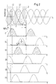
- FIG. 2 shows an example of the activation of the switches S1, S2,..., S6 of the circuit arrangement from FIG. 1.
- the time profiles of pure inductive reactive currents in the three phases L1, L2, L3 of the 3-phase AC network is shown.
- the phase shift between the reactive currents is 120 ° or 240 °.
- the entire network period T can be divided into twelve basically identical sections a1, a2, ..., a12.
- switch S1 is permanently closed (that is, positive current only flows into phase L1 (indicated by arrow A in FIG.
- Fig. 3 shows a detail of the switching program described above for about the middle of section a3 and the resulting current i L in inductance L.
- the switch S1 is continuously closed, while the duty cycle E4 or E5 of the switch S4 or S5 from switching period to Switching period decreases and the duty cycle E6 of the switch S6 increases from switching period to switching period.
- the mean value of the current in the individual phases L1, L2, L3 is approximately sinusoidal. Due to the switching processes, however, high-frequency vibrations are superimposed on the currents, which are smoothed by the smoothing filter F by averaging.
- the smoothing filter F also assumes a certain EMC filtering.
- the amplitude of the current mean value of the respective phase L1, L2, L3 is proportional to the current i L.
- the amplitude of the desired compensation current can thus be set by a suitable choice of i L. By changing the switching program accordingly, you can choose whether the compensation current should be inductive or capacitive.
- FIG. 4 shows an exemplary basic circuit of a control part for controlling the switches S1, S2, ..., S6 from FIG. 1.
- the entire switching program which repeats itself within the network period, is stored in an EPROM 10.
- 8 bits of a memory word byte
- 6 bits are used to control the electronic switches S1 ... S6 of the power section according to FIG. 1 via a memory (latch) 12 and a driver 14.
- the memory 12 effects a synchronous switching.
- the address of the EPROM 10 is generated by a 12-bit binary counter 16, which assumes all 4096 states once within a network period.
- the least significant 5 bits of the counter 16 form the switching period (" ⁇ T" in Fig. 3).
- the higher-order 7 bits of the counter 16 are passed through an adder 18, whereby a phase shift of the switching program can take place via a second input of the counter 16.
- this phase shift can be up to +/- 45 ° and is used as a manipulated variable in order to readjust the actual value from i l (equal to i L, actual) to a target value i L, intended by means of a controller 20.
- This is formed by means of a second controller 22 in the sense of a cascade control for tracking the actual value of the network current I network, is according to a network current setpoint i network, target.
- An analog / digital converter 24 is provided between the analog controllers 20 and 22 and the digital adder 18.
- the counter 16 is synchronized by means of a voltage-controlled oscillator (VCO) 26 and a "phase-locked loop" circuit 28 in a known manner with its most significant bit (MSB) to the voltage zero crossing of a line phase L1.
- VCO voltage-controlled oscillator
- MSB most significant bit
- the switching programs E1 / E4 of the switches S1 / S4 etc. are exchanged. Such a switching program can of course also be implemented by suitable programming of a microcontroller or signal processor.
Landscapes
- Engineering & Computer Science (AREA)
- Power Engineering (AREA)
- Control Of Electrical Variables (AREA)
- Ac-Ac Conversion (AREA)
- Rectifiers (AREA)
- Supply And Distribution Of Alternating Current (AREA)
Applications Claiming Priority (2)
| Application Number | Priority Date | Filing Date | Title |
|---|---|---|---|
| DE19703318 | 1997-01-30 | ||
| DE1997103318 DE19703318C2 (de) | 1997-01-30 | 1997-01-30 | Elektrische Schaltungsanordnung und Verfahren zur verlustleistungsarmen Beeinflussung von Grundwellen-Blindstrom und/oder Oberwellenströmen in 3-Phasen-Wechselstromnetzen mit oder ohne Nulleiter |
Publications (2)
| Publication Number | Publication Date |
|---|---|
| EP0856930A2 true EP0856930A2 (fr) | 1998-08-05 |
| EP0856930A3 EP0856930A3 (fr) | 1999-12-29 |
Family
ID=7818741
Family Applications (1)
| Application Number | Title | Priority Date | Filing Date |
|---|---|---|---|
| EP98101652A Withdrawn EP0856930A3 (fr) | 1997-01-30 | 1998-01-30 | Circuit électrique et méthode pour influencer sans pertes la composante fondamentale de la puissance réactive et/ou les courants harmoniques dans les réseaux triphasés avec ou sans conducteur neutre |
Country Status (2)
| Country | Link |
|---|---|
| EP (1) | EP0856930A3 (fr) |
| DE (1) | DE19703318C2 (fr) |
Cited By (3)
| Publication number | Priority date | Publication date | Assignee | Title |
|---|---|---|---|---|
| EP1503475A1 (fr) * | 2003-07-30 | 2005-02-02 | Siemens Aktiengesellschaft | Procédé de connexion pour un compensateur de puissance reactive |
| CN103001222A (zh) * | 2012-11-16 | 2013-03-27 | 新安县电业公司 | 一种防止输电设备电容器损坏的方法及装置 |
| CN108767860A (zh) * | 2018-03-12 | 2018-11-06 | 天津大学 | 一种应用于三相三线制系统的容性无功电流提取方法 |
Family Cites Families (2)
| Publication number | Priority date | Publication date | Assignee | Title |
|---|---|---|---|---|
| DE2832229C2 (de) * | 1978-07-20 | 1989-05-18 | Licentia Patent-Verwaltungs-Gmbh, 6000 Frankfurt | Thyristorgeschaltete Leistungskondensatoren oder Filterkreise |
| US5465040A (en) * | 1993-09-23 | 1995-11-07 | Yasotornrat; Hemtong | Three phase power factor correction device and method |
-
1997
- 1997-01-30 DE DE1997103318 patent/DE19703318C2/de not_active Expired - Lifetime
-
1998
- 1998-01-30 EP EP98101652A patent/EP0856930A3/fr not_active Withdrawn
Cited By (5)
| Publication number | Priority date | Publication date | Assignee | Title |
|---|---|---|---|---|
| EP1503475A1 (fr) * | 2003-07-30 | 2005-02-02 | Siemens Aktiengesellschaft | Procédé de connexion pour un compensateur de puissance reactive |
| WO2005020403A1 (fr) * | 2003-07-30 | 2005-03-03 | Siemens Aktiengesellschaft | Procede de mise sous tension pour compensateur de puissance apparente |
| US7183752B2 (en) | 2003-07-30 | 2007-02-27 | Siemens Aktiengesellschaft | Connection method for a static VAR compensator |
| CN103001222A (zh) * | 2012-11-16 | 2013-03-27 | 新安县电业公司 | 一种防止输电设备电容器损坏的方法及装置 |
| CN108767860A (zh) * | 2018-03-12 | 2018-11-06 | 天津大学 | 一种应用于三相三线制系统的容性无功电流提取方法 |
Also Published As
| Publication number | Publication date |
|---|---|
| DE19703318A1 (de) | 1998-08-13 |
| DE19703318C2 (de) | 1999-10-14 |
| EP0856930A3 (fr) | 1999-12-29 |
Similar Documents
| Publication | Publication Date | Title |
|---|---|---|
| DE69836312T2 (de) | Gerät zur Versorgung einer Vielzahl von Schwingkreisen durch einen Wechselrichter-Stromgenerator | |
| DE69205413T2 (de) | Elektronische vorrichtung zur elektrischen energieumwandlung. | |
| EP3183809B1 (fr) | Onduleur raccordé à un réseau, système d'onduleur et procédé de fonctionnement pour un système d'onduleur | |
| DE102005028945A1 (de) | Motorantriebsvorrichtung | |
| EP2178201A1 (fr) | Procédé et système de commande destinés à déformer une tension de changement d'alimentation dans une tension de fonctionnement de consommation dotée d'une valeur à effet réglable | |
| EP3879558B1 (fr) | Générateur de plasma, dispositif de traitement au plasma et procédé de fourniture pulsée de l'énergie électrique | |
| DE2446635A1 (de) | Wechselrichteranordnung mit zwei dreiphasigen steuerbaren wechselrichtern | |
| DE2652275A1 (de) | Einrichtung ohne prinzipbedingte verluste zur entnahme von praktisch rein sinusfoermigem, netzfrequentem strom aus wechsel- oder drehspannungsnetzen und zur ueberfuehrung der entnommenen elektrischen energie in galvanisch verbundene gleichspannungssysteme oder gleichspannungszwischensysteme | |
| WO2014206704A1 (fr) | Ensemble mutateur à mutateurs multi-étages câblés en parallèle et son procédé de commande | |
| DE2651229A1 (de) | Geregelte hochspannungs-gleichstromversorgung | |
| DE2446943C2 (de) | Schaltungsanordnung zur schnellen Erfassung und Kompensation der Verbraucherblindleistungsaufnahme in ein- oder mehrphasigen Wechselstromnetzen | |
| EP1398867B1 (fr) | Stabilisateur de tension d'un réseau à tension alternatif électrique et procédé pour conduire le stabilisateur | |
| EP0856930A2 (fr) | Circuit électrique et méthode pour influencer sans pertes la composante fondamentale de la puissance réactive et/ou les courants harmoniques dans les réseaux triphasés avec ou sans conducteur neutre | |
| DE19531210A1 (de) | Steuersystem für einphasigen PWM-Wandler | |
| DE19605419B4 (de) | Verfahren zur Beseitigung von Abweichungen der Ist-Spannung in einem Drehstromnetz von einer vorgegebenen Soll-Spannung | |
| EP3782275B1 (fr) | Convertisseur de tension continue et son fonctionnement | |
| EP3516763B1 (fr) | Procédé de production d'un courant alternatif au moyen d'un convertisseur d'une éolienne | |
| DE10120497B4 (de) | Elektronisches Vorschaltgerät | |
| EP2274827B1 (fr) | Procédé pour faire fonctionner un circuit convertisseur et dispositif pour la mise en oeuvre du procédé | |
| DE102012206976B4 (de) | Schaltwandler zum Betreiben mindestens einer LED | |
| AT402133B (de) | Steuereinrichtung für die energieversorgung eines verbraucherkreises eines gleichstromverbrauchers und ein verfahren zum betrieb einer derartigen steuereinrichtung | |
| EP1298781B1 (fr) | Dispositif de conversion de puissance et procédé pour adapter une tension continue variable | |
| DE3900958C2 (fr) | ||
| EP0491690B1 (fr) | Procede de reglage par impulsion pour un onduleur a plusieurs etages | |
| EP4560911A1 (fr) | Procédé de commande à fréquence variable pour actionneur de frein modulaire |
Legal Events
| Date | Code | Title | Description |
|---|---|---|---|
| PUAI | Public reference made under article 153(3) epc to a published international application that has entered the european phase |
Free format text: ORIGINAL CODE: 0009012 |
|
| AK | Designated contracting states |
Kind code of ref document: A2 Designated state(s): CH FI FR GB IT LI SE |
|
| AX | Request for extension of the european patent |
Free format text: AL;LT;LV;MK;RO;SI |
|
| PUAL | Search report despatched |
Free format text: ORIGINAL CODE: 0009013 |
|
| AK | Designated contracting states |
Kind code of ref document: A3 Designated state(s): AT BE CH DE DK ES FI FR GB GR IE IT LI LU MC NL PT SE |
|
| AX | Request for extension of the european patent |
Free format text: AL;LT;LV;MK;RO;SI |
|
| 17P | Request for examination filed |
Effective date: 20000602 |
|
| AKX | Designation fees paid |
Free format text: CH FI FR GB IT LI SE |
|
| REG | Reference to a national code |
Ref country code: DE Ref legal event code: 8566 |
|
| STAA | Information on the status of an ep patent application or granted ep patent |
Free format text: STATUS: THE APPLICATION IS DEEMED TO BE WITHDRAWN |
|
| 18D | Application deemed to be withdrawn |
Effective date: 20010801 |