EP3879558B1 - Générateur de plasma, dispositif de traitement au plasma et procédé de fourniture pulsée de l'énergie électrique - Google Patents
Générateur de plasma, dispositif de traitement au plasma et procédé de fourniture pulsée de l'énergie électrique Download PDFInfo
- Publication number
- EP3879558B1 EP3879558B1 EP21171624.6A EP21171624A EP3879558B1 EP 3879558 B1 EP3879558 B1 EP 3879558B1 EP 21171624 A EP21171624 A EP 21171624A EP 3879558 B1 EP3879558 B1 EP 3879558B1
- Authority
- EP
- European Patent Office
- Prior art keywords
- pulse
- switching unit
- pulses
- process chambers
- power
- Prior art date
- Legal status (The legal status is an assumption and is not a legal conclusion. Google has not performed a legal analysis and makes no representation as to the accuracy of the status listed.)
- Active
Links
Images





Classifications
-
- H—ELECTRICITY
- H01—ELECTRIC ELEMENTS
- H01J—ELECTRIC DISCHARGE TUBES OR DISCHARGE LAMPS
- H01J37/00—Discharge tubes with provision for introducing objects or material to be exposed to the discharge, e.g. for the purpose of examination or processing thereof
- H01J37/32—Gas-filled discharge tubes
- H01J37/32917—Plasma diagnostics
- H01J37/32935—Monitoring and controlling tubes by information coming from the object and/or discharge
- H01J37/32944—Arc detection
-
- H—ELECTRICITY
- H01—ELECTRIC ELEMENTS
- H01J—ELECTRIC DISCHARGE TUBES OR DISCHARGE LAMPS
- H01J37/00—Discharge tubes with provision for introducing objects or material to be exposed to the discharge, e.g. for the purpose of examination or processing thereof
- H01J37/32—Gas-filled discharge tubes
- H01J37/32009—Arrangements for generation of plasma specially adapted for examination or treatment of objects, e.g. plasma sources
- H01J37/32082—Radio frequency generated discharge
- H01J37/32137—Radio frequency generated discharge controlling of the discharge by modulation of energy
- H01J37/32146—Amplitude modulation, includes pulsing
-
- H—ELECTRICITY
- H01—ELECTRIC ELEMENTS
- H01J—ELECTRIC DISCHARGE TUBES OR DISCHARGE LAMPS
- H01J37/00—Discharge tubes with provision for introducing objects or material to be exposed to the discharge, e.g. for the purpose of examination or processing thereof
- H01J37/32—Gas-filled discharge tubes
- H01J37/32009—Arrangements for generation of plasma specially adapted for examination or treatment of objects, e.g. plasma sources
- H01J37/32082—Radio frequency generated discharge
- H01J37/32137—Radio frequency generated discharge controlling of the discharge by modulation of energy
- H01J37/32155—Frequency modulation
-
- H—ELECTRICITY
- H01—ELECTRIC ELEMENTS
- H01J—ELECTRIC DISCHARGE TUBES OR DISCHARGE LAMPS
- H01J37/00—Discharge tubes with provision for introducing objects or material to be exposed to the discharge, e.g. for the purpose of examination or processing thereof
- H01J37/32—Gas-filled discharge tubes
- H01J37/32009—Arrangements for generation of plasma specially adapted for examination or treatment of objects, e.g. plasma sources
- H01J37/32082—Radio frequency generated discharge
- H01J37/32174—Circuits specially adapted for controlling the RF discharge
-
- H—ELECTRICITY
- H01—ELECTRIC ELEMENTS
- H01J—ELECTRIC DISCHARGE TUBES OR DISCHARGE LAMPS
- H01J37/00—Discharge tubes with provision for introducing objects or material to be exposed to the discharge, e.g. for the purpose of examination or processing thereof
- H01J37/32—Gas-filled discharge tubes
- H01J37/32431—Constructional details of the reactor
- H01J37/32798—Further details of plasma apparatus not provided for in groups H01J37/3244 - H01J37/32788; special provisions for cleaning or maintenance of the apparatus
- H01J37/32889—Connection or combination with other apparatus
-
- H—ELECTRICITY
- H01—ELECTRIC ELEMENTS
- H01J—ELECTRIC DISCHARGE TUBES OR DISCHARGE LAMPS
- H01J37/00—Discharge tubes with provision for introducing objects or material to be exposed to the discharge, e.g. for the purpose of examination or processing thereof
- H01J37/32—Gas-filled discharge tubes
- H01J37/32431—Constructional details of the reactor
- H01J37/32798—Further details of plasma apparatus not provided for in groups H01J37/3244 - H01J37/32788; special provisions for cleaning or maintenance of the apparatus
- H01J37/32899—Multiple chambers, e.g. cluster tools
-
- H—ELECTRICITY
- H01—ELECTRIC ELEMENTS
- H01J—ELECTRIC DISCHARGE TUBES OR DISCHARGE LAMPS
- H01J37/00—Discharge tubes with provision for introducing objects or material to be exposed to the discharge, e.g. for the purpose of examination or processing thereof
- H01J37/32—Gas-filled discharge tubes
- H01J37/32917—Plasma diagnostics
- H01J37/3299—Feedback systems
-
- H—ELECTRICITY
- H05—ELECTRIC TECHNIQUES NOT OTHERWISE PROVIDED FOR
- H05H—PLASMA TECHNIQUE; PRODUCTION OF ACCELERATED ELECTRICALLY-CHARGED PARTICLES OR OF NEUTRONS; PRODUCTION OR ACCELERATION OF NEUTRAL MOLECULAR OR ATOMIC BEAMS
- H05H1/00—Generating plasma; Handling plasma
- H05H1/24—Generating plasma
- H05H1/46—Generating plasma using applied electromagnetic fields, e.g. high frequency or microwave energy
Definitions
- the present invention relates to a plasma generator for pulsed provision of electrical power with a frequency of at least 40KHz, a plasma treatment device and a method for pulsed provision of electrical power with a frequency of at least 40KHz.
- wafers are loaded into so-called wafer boats, some of which consist of electrically conductive plates, and placed in corresponding process chambers. Electrical power with a frequency of at least 40KHz is then applied to the wafer boats in order to generate a plasma from a suitable process gas between the plates and between wafers held on the plates.
- a plasma treatment device is in the DE 10 2015 004 419 A1 shown to the applicant.
- Such plasma treatment devices generally consist of a single process chamber to which a single plasma generator is assigned.
- a plasma generator usually has a controllable power supply with an output, which is suitable for outputting a direct current with a predetermined voltage and / or strength at its output, a converter that is suitable for converting a direct current at the input into an alternating current with a predetermined frequency at least 40KHz as an output signal and apply the output signal to the connected process chamber.
- the power supply and the converter are usually controlled via a controller that provides the required Power for the process chamber is determined and corresponding control signals are generated.
- an arc suppression unit is also provided, which is suitable for receiving current process data about processes in the process chamber and current data from the power supply and/or the switch and evaluating them in real time in order to detect a flashover or an impending flashover, the arc suppression unit is connected to the power supply and/or the switch in order to control them, if necessary, in response to the detection of a flashover or an impending flashover, in order to avoid or quickly suppress flashovers in the process chamber.
- the electrical power is usually provided periodically as a pulse by the respective plasma generator, whereby a duty cycle (quotient of pulse duration and period duration) of less than 0.1 is generally set over long periods of time.
- a duty cycle (quotient of pulse duration and period duration) of less than 0.1 is generally set over long periods of time.
- Such pulsed operation of a plasma in the process chamber has proven to be particularly advantageous.
- 90% of the available continuous power of a plasma generator remains unused over long stretches of the process.
- the JP H03 247 748 A which shows a plasma treatment device in which different materials are treated with plasma simultaneously in separate vacuum chambers.
- the plasma energy is provided in a partial time process via a controller that controls the corresponding switches.
- the control is based on temperature measurement signals from the chambers and the materials to be treated. Further plasma treatment devices, which could supply several process units with one plasma generator, result from the KR 2016 0097438 A , the KR 2016 0049628 A or the WO 2017 011264 A1 .
- the present invention is therefore based on the object of making the provision of electrical power more efficient. According to the invention, this object is achieved by a plasma generator according to claim 1, a plasma treatment device according to claim 9 and a method according to claim 11. Further refinements of the invention result, among other things, from the subclaims.
- a plasma generator for the pulsed provision of electrical power with a frequency of at least 40KHz to at least two process chambers, the plasma generator having the following: a control unit which is suitable for obtaining and evaluating process data about processes in the at least two process chambers; a controllable power supply with an output which is suitable for outputting a direct current with a predetermined voltage and/or strength at its output in response to a control signal from the control unit; and a switching unit having a first input connected to the output of the power supply and at least two switching unit outputs for respective connection to one of the at least two process chambers; wherein the switching unit is adapted to form an alternating current with a predetermined frequency of at least 40KHz as an output signal from a direct current at the input and to output the output signal in response to a control signal from the control unit as a pulse selectively for a predetermined pulse duration to one of the switching unit outputs; wherein the control unit is suitable for coordinating power requirements of the at least two process chambers and controlling the power supply
- Such a plasma generator enables the coordinated delivery of pulsed conduction to a variety of process chambers, thereby increasing the efficiency of the plasma generator.
- Purchase costs for a multi-chamber plasma treatment unit can be significantly reduced because the number of plasma generators required can be at least halved if not further reduced.
- process chambers in which similar processes are carried out can be coordinated efficiently.
- control unit has a number of controllers corresponding to the number of process units to be connected to the switching unit, each controller being suitable for receiving process data about processes in a respective one of the process chambers, each controller being connected to the power supply and/or the switch is available to control this in response to the process data received. This can ensure good and safe control of the respective processes.
- the plasma generator preferably has at least one arc suppression unit, which is suitable for receiving current process data about processes in the at least two process chambers and current data from the power supply and/or the switch and evaluating them in real time in order to detect a flashover or an impending flashover , wherein the arc suppression unit is connected to the power supply and / or the switch in order to control them, if necessary, in response to the detection of a rollover or an impending rollover.
- the arc suppression unit may form part of the control unit.
- the controllers and/or the at least one arc suppression unit can be designed as separate software modules that can be executed on a common processor or on separate processors of the plasma generator.
- the switching unit has at least a third switching unit output which is suitable for connection to at least one further process chamber or an absorber, and wherein the switching unit is suitable for selectively outputting the output signal as a pulse for a predetermined pulse duration in response to an incoming control signal from the control unit to create one of the switching unit outputs in order to enable even more efficient use of the plasma generator.
- the switching unit can have at least one switching unit output which is suitable for connection to an absorber, the switching unit being suitable for sending the output signal as a pulse selectively to the switching unit output in response to an incoming control signal for the absorber in order to avoid or prevent an overload or flashover in a process chamber.
- control unit can be designed in such a way that it coordinates the sum of the pulse duration and a corresponding pulse pause at the respective switching unit outputs in such a way that the sum is the same in each case or is a multiple of the sum at the other switching unit output at one of the switching unit outputs.
- the control unit is designed so that it shifts pulses in time with respect to the power requirements if the power requirements would lead to an overlapping of pulses at different outputs, with a corresponding time shift being chosen so that the energy output via the respective outputs over time in Substantially corresponds to the performance requirement.
- the control unit can be designed in such a way that it divides individual pulses into two separate pulses with respect to the power requirements and shifts them in time if the power requirements would lead to an overlap of pulses at different outputs, with a corresponding division and time shift being selected so that the energy output via the respective outputs over time essentially corresponds to the power requirement.
- control unit it is also additionally or alternatively possible for the control unit to be designed in such a way that it shifts individual pulses in time with respect to the power requirements if the power requirements would lead to an overlapping of pulses at different outputs, with a corresponding time shift being chosen so that the Energy output via the respective outputs over time essentially corresponds to the power requirement.
- control unit is designed so that it can change at least one of the following parameters of a pulse: a position of a pulse in a pulse sequence, a division of a pulse into partial pulses, a pulse duration and an amplitude of a pulse when specific performance requirements arise would lead to an overlapping of pulses at different outputs.
- the plasma generator is designed for the pulsed provision of electrical power with a frequency of at least 40KHz to at least three process chambers and further has the following: a control unit which is suitable for obtaining and evaluating process data about processes in the at least three process chambers; a further controllable power supply with an output which is suitable for outputting a direct current with a predetermined voltage and/or strength at its output in response to a control signal from the control unit; and a further switching unit having a power input connected to the output of the power supply and at least three switching unit outputs for respective connection to one of the at least three process chambers; wherein the switching unit is suitable for forming an alternating current with a predetermined frequency of at least 40KHz as an output signal from a direct current at the input and for outputting the output signal as a pulse selectively for predetermined pulse durations to one of the switching unit outputs in response to a control signal from the control unit; wherein the control unit is suitable for coordinating power requirements of the at least three process chambers and controlling
- the invention also relates to a plasma treatment device with at least two separate process chambers, in each of which a plasma can be generated, and a plasma generator of the type described above, with process chambers each being connected to one of the switching unit outputs of the switching unit.
- such a plasma treatment device has at least three separate process chambers, the switching unit of the plasma generator having at least three switching unit outputs, and the process chambers each are connected to one of the switching unit outputs.
- it can also have an absorber, wherein the switching unit of the plasma generator has at least three switching unit outputs, and the absorber is connected to one of the switching unit outputs.
- the invention also relates to a method for pulsed provision of electrical power with a predetermined frequency of at least 40KHz to at least two separate process chambers, with the following steps: Providing a direct current with a predetermined voltage and / or strength at an input of a switching unit, in response to a control signal from a control unit; forming, from the direct current, an alternating current output signal with a predetermined frequency of at least 40KHz in the switching unit and, in response to a control signal from the control unit, selectively outputting the alternating current output signal as a pulse with a predetermined pulse duration at one of at least two switching unit outputs of the switching unit, each of which is connected to one of at least two separate process chambers; wherein the control unit, responsive to power requirements of the at least two process chambers and responsive to process data about processes in the at least two process chambers, generates control signals for providing the direct current and control signals for selectively outputting the alternating current output signal, which are coordinated to the respective ones of the with The switching unit outputs connected to the process
- the control unit can make an adjustment according to predetermined fixed rules or rules that can be set by an operator.
- the control unit can compare the power output in pulses per process chamber over a period of time with the power requested over the period of time and automatically adjust at least one parameter of a pulse based on the comparison.
- the electrical power is provided to at least three separate process chambers, the switching unit having at least three switching unit outputs, each of which is connected to one of the at least three separate process chambers; wherein the control unit, responsive to power requirements of the at least two process chambers and responsive to process data about processes in the at least three process chambers, generates control signals for providing the direct current and control signals for selectively outputting the alternating current output signal, which are coordinated to the respective ones of the
- the switching unit outputs connected to the process chambers essentially provide the power corresponding to the performance requirements over time as pulses, the pulses for the process chambers being offset in time from one another, but the process chambers being operated at the same time.
- the switching unit can have at least three switching unit outputs, one of which is connected to an absorber that is suitable for receiving and absorbing electrical power, and the control unit is able to monitor the processes in the respective process chambers and the occurrence or to recognize the risk of a flashover in one of the process chambers, and in response to this, to redirect the output signal over a pulse duration or at least a part thereof into the absorber instead of into a corresponding one of the process chambers.
- control unit coordinates the sum of the pulse duration and a corresponding pulse pause at the respective switching unit outputs so that the sum is the same in each case or is a multiple of the sum at another switching unit output at one switching unit output.
- the method is for pulsed provision of electrical power with a predetermined frequency of at least 40KHz to at least three separate process chambers, and has the following further steps: Providing a direct current with a predetermined voltage and / or strength at an input of another Switching unit, responsive to a control signal from the control unit; Forming, from the direct current, an alternating current output signal with a predetermined frequency of at least 40KHz in the further switching unit and, in response to a control signal from the control unit, selectively outputting the alternating current output signal as a pulse with a predetermined pulse duration at one of at least three switching unit outputs of the further switching unit, each of which is connected to one of the at least three separate process chambers; wherein the control unit, responsive to power requirements of the at least three process chambers and responsive to process data about processes in the at least three process chambers, generates control signals for providing the direct current and control signals for selectively outputting the alternating current output signal, which are coordinated to the respective ones of the with The switching unit outputs connected to
- the expression is intended to essentially encompass deviations of +/-5%, preferably +/-2%, from the stated value.
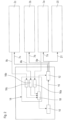
- Fig. 1 shows a schematic representation of a first embodiment of a plasma treatment device 1 with two process units 3a, 3b and a plasma generator 5.
- the process units 3a and 3b can each have the same structure and each have a process chamber for holding one or more substrates, in particular semiconductor wafers or PV -Substrates.
- the process chambers can be sealed tightly and the process units 3a and 3b have different means, not shown, for setting a desired gas atmosphere within the respective process chambers, such as pumps and a gas cabinet. While each process chamber is usually assigned its own pump, a gas cabinet can supply several process chambers if necessary.
- Means for generating a plasma are also provided in the process chambers, which can be formed in part by a wafer boat, which, for example, is introduced into the process chamber together with the substrates and is electrically contacted there, as is the case, for example, in the above-mentioned DE 10 2015 004 419 A1 is described, which is made the subject of the present disclosure.
- the process units 3a, 3b are connected to the plasma generator 5 via power lines 7a and 7b and data connections 8a and 8b.
- the plasma generator 5 supplies electrical power with a frequency greater than 40KHz to the respective process units 3a and 3b via the power lines 7a, 7b.
- Data can be exchanged between the process units 3a, 3b and the plasma generator 5 via the data connections 8a and 8b.
- the data connections 8a and 8b can be wired or wireless.
- the process units 3a, 3b can provide the plasma generator 5 with different process data about processes in the respective process chambers.
- actual data regarding the actual incoming electrical power, the presence of a plasma, etc. can be transmitted, but also corresponding target data, as is also the case with known plasma treatment devices with a single process unit and a single plasma generator.
- the plasma generator 5 has a controllable power supply 10, a switching unit 12 and a control unit 14.
- the power supply has an input (not shown) and an output which is connected to an input of the switching unit 12 via a power line 15.
- the power supply 10 is suitable for outputting a direct current with a predetermined voltage and/or strength at its output in response to a control signal from the control unit 14, as is known in the art.
- the switching unit 12 has the aforementioned input which is connected to the power line 15 for receiving direct current from the power supply 10, as well as two separate outputs, one output being connected to the power line 7a and the other output being connected to the power line 7b.
- the switching unit 12 has a converter circuit which can form an alternating current with a predetermined frequency of at least 40KHz as an output signal from a direct current at the input.
- the converter circuit can, for example, have a bipolar transistor which forms a quasi sinusoidal signal (step-shaped signal) from the direct current provided by the power supply 10.
- the switching unit 12 has a switching part which, in response to a control signal from the control unit 14, applies the output signal formed in this way to one or the other output, i.e. to the process unit 3a or the process unit 3b.
- control unit 14 in turn has two separate controllers 16a, 16b, as well as a sheet suppression unit 18.
- the controllers 16a, 16b are connected to the process units 3a and 3b via the data connections 8a and 8b, respectively.
- the controllers 16a, 16b are each designed in a known manner to determine performance requirements for the process units 3a, 3b based on actual data and target data about the respective processes in the process units 3a, 3b. From these, the controllers 16a, 16b (or a downstream unit) then create control data for the power supply 10 and the switching unit 12.
- the controllers 16a, 16b are shown as separate units, they can also be designed as a single unit, which is one in Essentially parallel processing of data from the process units 3a and 3b is possible.
- the controllers 16a, 16b be designed as separate software routines that can be executed essentially in parallel and are executed on a processor.
- corresponding outputs of the controller are connected to corresponding inputs of the arc suppression unit 18.
- the arc suppression unit 18 can thus receive the performance requirements of the individual process units from the controllers 16a, 16b, or directly the control data created therefrom for the power supply 10 and the switching unit 12.
- the arc suppression unit 18 can also receive unprocessed data directly from the respective process units 3a, 3b.
- Such data are in particular those which make it possible to evaluate in real time whether a rollover has occurred in one of the process units 3a and 3b or whether one is imminent.
- the data required for this are known to those skilled in the art, as are the corresponding recognition algorithms, which are therefore not explained in more detail here.
- the arc suppression unit 18 can adapt the control signals to the power supply 10 and the switching unit 12 and provide the power to the respective process unit 3a, 3b in which the flashover occurs or a corresponding danger exists interrupt briefly.
- the arc suppression unit 18 can also be designed so that when it receives power requirement data from the individual process units, it creates control data for the power supply 10 and the switching unit 12. Of course, this is not necessary if this control data is already created by the controllers 16a, 16b.
- the arc suppression unit 18 is designed so that it coordinates the control data it creates itself or the control data created by the controllers 16a, 16b for the power supply 10 and the switching unit 12. The control data for the power supply 10 and the switching unit 12 must be coordinated in such a way that power is made available to the respective process units 3a, 3b in accordance with their performance requirements.
- control data for the power supply 10 and the switching unit 12 must also be coordinated in time, since power can only be made available at one of the outputs of the switching unit at any given time.
- the power is sent to the respective process units 3a, 3b as a pulse with a predetermined pulse duration provided.
- the respective pulses must therefore be coordinated via the control data for the power supply 10 and the switching unit 12 so that the pulses do not overlap, but the process chambers can still be operated at the same time.
- Fig. 2 shows a schematic representation of an alternative embodiment of a plasma treatment device 1, which in this embodiment has three process units 3a, 3b, 3c, an absorber 20 and a plasma generator 5. If the same or similar elements are present in the different embodiments, the same reference numbers are used.
- the process units 3a, 3b and 3c can be identical to those described above and are connected to the plasma generator 5 via power lines 7a, 7b and 7c and data connections 8a, 8b and 8c.
- the power lines 7a, 7b, and 7c are again used to supply electrical power with a frequency greater than 40KHz from the plasma generator 5 to the respective process units 3a, 3b and 3c.
- Data can again be exchanged between the process units 3a, 3b, 3c and the plasma generator 5 via the data connections 8a, 8b and 8c.
- the plasma generator 5 again has a controllable power supply 10, a switching unit 12 and a control unit 14.
- the power supply 10 can be identical to that described previously.
- the switching unit 12 again has an input via the power line 15 which is connected to the output of the power supply. In this embodiment, however, the switching unit has four separate outputs, with three of the outputs being connected to the power lines 7a, 7b and 7c and the fourth output being connected to the absorber via a power line 21.
- the switching unit 12 again has a converter circuit as described above and a switching part which selectively applies an output signal formed by the converter circuit to one of the outputs in response to a control signal from the control unit 14.
- the output signal can therefore be selectively applied to one of the process units 3a to 3c or to the absorber 20.
- control unit 14 in turn has three separate controllers 16a, 16b and 16c, as well as a sheet suppression unit 18.
- the controllers 16a, 16b, 16c and are connected to the process units 3a, 3b and 8c via respective data connections 8a, 8b and 8c .3c in connection.
- the controllers 16a, 16b and 16c can in turn be of the previously described type which is designed to determine performance requirements for the respective process unit 3a, 3b or 3c and, if necessary, also control data for the power supply 10 and/or the switching unit 12.
- Arc suppression unit 18 can also be essentially of the type described above, in this embodiment monitoring three process units 3a, 3b and 3c for the risk of flashovers. Furthermore, it coordinates the pulses provided by the switching unit 12 for three process units 3a, 3b and 3c.
- the arc suppression unit 18 can also be designed so that when it receives power requirement data from the individual process units, it creates control data for the power supply 10 and the switching unit 12. Of course, this is not necessary if this control data is already created by the controllers 16a, 16b.
- the arc suppression unit 18 is designed so that it coordinates the control data for the power supply 10 and the switching unit 12 that it creates itself or that is created by the controllers 16a, 16b, 16c.
- the control data for the power supply 10 and the switching unit 12 must be coordinated in such a way that power is made available to the respective process units 3a, 3b and 3c in accordance with their performance requirements.
- the control data for the power supply 10 and the switching unit 12 must also be coordinated in time, since power can only be made available at one of the outputs of the switching unit at any given time.
- the power is provided to the respective process units 3a, 3b and 3c as a pulse with a predetermined pulse duration.
- the respective pulses must therefore be coordinated via the control data for the power supply 10 and the switching unit 12 so that the pulses do not overlap, but the process chambers can still be operated at the same time.
- the arc suppression unit 18 is shown as a single unit that performs both the arc suppression function and the pulse coordination function, these functions may also be performed in separate units.
- the evaluation of the process data and the control data could be carried out separately for each of the process chambers and accordingly three units could be provided (again, for example, as separate software routines running in parallel).
- the arc suppression function detects a flashover or the risk of such, it can redirect the pulse actually prepared for one of the respective process units 3a, 3b and 3c into the absorber 20, which is suitable, instead of being directed into the respective process units 3a, 3b and 3c is to absorb the power impulse and convert it into heat, for example.
- Such a switching can take place for a whole pulse or for a partial pulse, as will be explained in more detail below.
- the data in particular the power requirement data of the individual process units or the desired control data for the power supply 10 and the switching unit 12, must come together in a coordination routine. As mentioned, this can take place in the arc suppression unit 18 or in a separate pulse coordination unit.
- the coordination routine the power requirement data of the individual process units determined by the controllers or the control data created therefrom for the power supply 10 and the switching unit 12 are brought together and checked to see whether conflicts exist. During this check, data about the power supply 10 and the switching unit 12, such as switching times, maximum power, maximum pulse duration (if limited), are also taken into account. Further data about the respective process units 3a, 3b and 3c and the processes taking place can also be taken into account.
- Such data can contain, for example, time tolerances for pulse delivery, tolerances with regard to the pulse amplitude, the minimum required and/or the maximum permitted energy input into the process and, if necessary, other parameters.
- This data can be consistent or change throughout a process. There are, among other things, processes in which precise pulse sequences with a fixed period length and with certain pulse amplitudes have to be maintained at certain times, while at other times in the process the period length and also the pulse amplitude are quite flexible is, but the energy input over time lies within narrow tolerances.
- the coordination unit can then coordinate the output pulses at the outputs of the control unit.
- processes are carried out in the respective process units 3a, 3b and 3c, which allow the setting of a period length (sum of pulse duration and pulse pause) which is the same or, for one of the processes, is an integer multiple of the period length of the other processes. This simplifies coordination significantly, as will be explained in more detail below using the pulse diagrams, but is also not necessary. Different coordination options are explained in more detail below using the pulse diagrams.
- Fig. 3 shows a schematic representation of a further alternative embodiment of a plasma treatment device 1.
- five process units 3a to 3e, an absorber 20 and a plasma generator 5 are provided. If the same or similar elements are present in the different embodiments, the same reference numbers are used again.
- the process units 3a to 3e can be identical to those described above and are connected to the plasma generator 5 via power lines 7a to 7e and data connections 8a to 8e.
- the power lines 7a to 7e are again used to supply electrical power with a frequency greater than 40KHz from the plasma generator 5 to the respective process units 3a to 3e.
- Data can again be exchanged between the process units 3a, 3b, 3c and the plasma generator 5 via the data connections 8a, 8b and 8c.
- the plasma generator 5 has two controllable power supplies 10a, 10b, two switching units 12a, 12b and a control unit 14.
- the power supplies 10a, 10b can be identical to the power supply described above.
- the power supplies 10a, 10b can be the same or different in terms of nominal power.
- the switching units 12a, 12b each have an input which is connected to the output of one of the power supplies via a power line 15a or 15b.
- the switching units have 12a, 12b respectively six separate outputs, five of the outputs being connected to the power lines 7a to 7e and thus to the plasma units 3a to 3e, and the sixth output being connected to the absorber 20 via a power line 21.
- the switching units 12a, 12b each have a converter circuit as described above and a switching part which selectively applies an output signal formed by the converter circuit to one of the outputs in response to a control signal from the control unit 14.
- the output signal of each switching unit 12a, 12b can therefore be selectively applied to one of the process units 3a to 3e or to the absorber 20.
- control unit 14 in turn has five separate controllers 16a to 16e, as well as a sheet suppression unit 18.
- the controllers 16a to 16e are connected to the process units 3a to 3e via respective data connections 8a to 8e.
- the controllers 16a to 16e can in turn be of the type described above, which is designed to determine performance requirements for the respective process unit 3a to 3e and, if necessary, also control data for the power supply 10 and / or the switching unit 12.
- the arc suppression unit 18 is configured to monitor the five process units 3a to 3e with regard to the risk of flashovers. Furthermore, it is configured in such a way that it distributes and coordinates the required pulses for the plasma units 3a to 3e across both power supplies 10a, 10b and both switching units 12a, 12b.
- the arc suppression unit 18 can distribute the required pulses to two power supplies (combination of power supply and switching unit) results in significantly greater flexibility with regard to the distribution of the pulses.
- time-overlapping pulses can now also be made available if this is necessary due to the performance requirements, as will be explained in more detail below.
- a corresponding coordination requires that the pulses are provided sequentially on a switching unit 12a or 12b, but that the switching units 12a, 12b can be controlled in such a way that they deliver pulses at the same time. When the pulses are delivered simultaneously via the separate ones Switching units 12a, 12b must then be connected to separate plasma units 3a to 3e.
- the arc suppression unit 18 is shown as a single unit that performs both the arc suppression function and the pulse coordination function, these functions may also be performed in separate units. In particular, if the coordination becomes more complex and possibly impairs the arc suppression function, the pulse coordination function could take place in a separate unit.
- the plasma generator 5 is also shown as a single plasma generator with two separate power supplies. Of course, two separate plasma generators 5 could also be provided here, which are respectively connected to the plasma units 3a to 3e and the absorber, and which are coordinated accordingly via a common control unit. However, a single unit is preferred because the communication between the arc suppression unit 18 and the power supply(s) 10a, 10b and the switching unit(s) 12a, 12b runs over real-time data connections that are mechanically sensitive and therefore preferably not routed outside the respective unit should be.
- the number of plasma units to be supplied and the structure of a plasma generator are not limited to the specific embodiments shown. Rather, even more plasma units could be equipped with a plasma generator, such as the one in Fig. 3 is shown to be supplied. It is also possible, for example, to provide three power supplies with a larger number of plasma units in the plasma generator, with the complexity of the pulse coordination increasing as the number of process chambers and power supplies increases. According to the invention, however, the number of plasma units should be higher than the number of available power supplies and in particular should be at least twice as high.
- a plasma treatment device with eight plasma units (+ 1 optional absorber) and a plasma generator with two separate ones Power supplies, as in Fig. 3 shown, or considered with two separate plasma generators and a common control unit.
- Figures 4 to 7b show different exemplary pulse sequences that can be provided via a plasma generator 5 according to the invention.
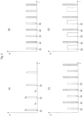
- FIG. 4A a classic pulse sequence, as previously provided by plasma generators.
- An alternating current pulse 30 with a frequency of at least 40KHz and a predetermined power (P) is output for a predetermined time period t on of, for example, 5ms.
- P predetermined power
- a pulse pause t off of, for example, 45 ms followed by another pulse with a time period t on of, for example, 5 ms.
- Fig. 4B shows an alternative pulse sequence as produced by a plasma generator according to the invention, for example in Fig. 1 shown can be made available.
- the exemplary pulse sequence consists of pulses 30 and pulses 40, with the pulses 30 being made available, for example, to the process unit 3a and the pulses 40 to the process unit 3b.
- pulses 30 and 40 each have the same power and the same pulse duration t on of, for example, 5 ms.
- pulses 30 - 30 / 40 - 40 for the respective process unit 3a/3b there is a pulse pause t off of, for example, 45ms.
- pulses 30 - 40 - 30 there is a pulse pause t off of, for example, 20ms. While each individual process unit 3a, 3b is operated with a duty cycle of 0.1, the plasma generator is operated with a duty cycle of 0.2 and is therefore utilized significantly better.
- Fig. 4C shows a further exemplary pulse sequence as produced by a plasma generator according to the invention, for example in Fig. 1 shown can be made available.
- the exemplary pulse sequence again consists of pulses 30 and pulses 40, with the pulses 30 being made available, for example, to the process unit 3a and the pulses 40 to the process unit 3b.
- the pulses 30 and 40 each have different power but again the same pulse duration t on of, for example, 5ms and also the same pulse pauses, as in Fig. 4B .
- the aim here is to show that the plasma generator is able not only to interleave the same pulses but also to provide pulses with different power, which is possible, for example, by appropriately controlling the power supply 10.
- Fig. 4D shows a further exemplary pulse sequence as produced by a plasma generator according to the invention, for example in Fig. 1 shown can be made available.
- the exemplary pulse sequence again consists of pulses 30 and pulses 40, with the pulses 30 being made available, for example, to the plasma unit 3a and the pulses 40 to the process unit 3b.
- the pulses have 30 and 40 as in Fig. 4C each different power and this time also different pulse duration t on of, for example, 15ms for the pulses 30 and 5ms for the pulses 40.
- the pulse pauses between the pulses 30 - 40 are each, for example, 10ms and between the pulses 40 - 30, for example, 20ms each.
- the pulses for plasma processes which are pulsed with the same period length (or with period lengths that are multiples of each other), can easily be interleaved and provided with a single plasma generator.
- a corresponding control unit for controlling a power supply can evaluate corresponding data and, if necessary, also look one or more cycles ahead in order to recognize when conflicts between pulses are to be expected and, if necessary, prepare for shifts. For example, if a maximum pulse pause t off in a process - with a normal pulse pause of 45ms - is 50ms, but a shift of +10ms is required in two cycles, then a +5ms shift can occur in two consecutive cycles, so that in two There is a 50ms pulse pause between successive cycles. However, shifts should preferably be chosen so that over longer periods of time, for example 50 cycles, energy input into the process corresponds to the performance requirements or remains unchanged over time.
- FIGS. 5A to 5D show different exemplary pulse sequences, for example via a plasma generator 5 according to Fig. 2 to be provided.
- a plasma generator 5 according to Fig. 2 to be provided.
- three different pulses 30, 40, 50 are provided for different process units 3a to 3c.
- Fig. 5A shows a pulse sequence with pulses 30, 40, 50, each of which has the same pulse duration t on of, for example, 5ms and the same line.
- a pulse pause t off of, for example, 45ms.
- pulse pauses t off of, for example, 10ms - 15ms - 10ms. While each individual process unit 3a, 3b is operated with a duty cycle of 0.1, the plasma generator is now operated with a duty cycle of 0.3.
- the Fig. 5B shows a pulse sequence with pulses 30, 40, 50, which, however, differ in terms of their pulse durations t on and also in terms of their power.
- the pulses 30 - 30 / 40 - 40 / 50 - 50 each have the same period length of, for example, 50ms, so that the pulses are easy to interleave.
- Fig. 5C shows another exemplary pulse sequence similar Fig. 5B with pulses 30, 40, 50, which differ in terms of their pulse durations t on and also in terms of their power.
- the pulses 30 - 30 / 40 - 40 each have the same Period length, for example, 50ms, while pulses 50 - 50 have a period length twice as long, for example 100ms.
- Fig. 5D shows another exemplary pulse sequence similar Fig. 5B with pulses 30, 40, 50, which differ in terms of their pulse durations t on and also in terms of their power, but the pulses 30 - 30 / 40 - 40 / 50 - 50 each have the same period length.
- this pulse sequence shows, by way of example, the intervention of the arc suppression unit 18 in the regular pulse sequence.
- a flashover was detected in the plasma unit 3c during the first half of the second pulse 50, whereupon the arc suppression unit 18 controlled the switching unit 12 in real time in order to redirect the second half of the pulse 50 into the absorber. This can be done quickly and no power fluctuations are generated in the subsequent pulses, which could occur if the plasma unit 3c was simply separated from the plasma generator 5, since the power is already provided in the switching unit.
- the Figure 6 shows at (A) an exemplary pulse train request (power request) of three process chambers, for example from the arc suppression unit 18 according to Fig. 2 is to be processed and coordinated and at (B) an exemplary pulse sequence that is responsive to the pulse sequence request from the plasma generator Fig. 2 is delivered.
- pulses 30, 40, 50 with different pulse durations and different powers are requested, with a corresponding requirement profile being created, for example, by the controllers 16a to 16c.
- the pulses 30 - 30 / 40 - 40 / 50 - 50 also have different period lengths, so that the pulse train request requests pulses partially overlapping or directly one after the other.
- the arc suppression unit 18 or another control unit must now coordinate the pulses to be output so that they are output in a suitable manner, whereby the needs of the plasma units are taken into account as much as possible.
- the pulses 30 must not undergo any changes, since the corresponding plasma unit does not allow any deviations, at least during the current phase of the process.
- the output pulses are therefore 30 (see Fig. 6B ) exactly match the requested pulses.
- the processes in the plasma units 3b and 3c allow deviations in the pulses within specified limits as long as the total energy input remains constant over time.
- the first pulse is therefore 50 in Fig.
- the second pulse 50 which would completely overlap with a pulse 30 according to the pulse request, was here divided into two parts 50-1, 50-2, with part 50-1 being ahead of the corresponding pulse 30 and part 50-2 being behind it Pulse 30 was postponed.
- the sum of the duration of the partial pulses 50-1, 50-2 corresponds to the duration of a normal pulse 50. In addition to such a division, it would also have been possible to shift the pulse 50 completely behind the pulse 30, provided that a maximum pulse pause between pulses is permitted 50 - 50 would not have been exceeded.
- the third and fourth pulses 40 were also shifted in time to enable a proper pulse sequence. If none of the overlapping pulses necessarily has to occur at a certain time, both can also be shifted in the case of overlapping pulses, in which case the shift will usually be in opposite directions. While one is moved forward, the other is moved backwards. This means that any required pulse pauses between the same pulses in a chamber can be better maintained.
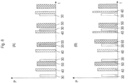
- the figure 8(A) again shows an exemplary pulse train requirement (power requirement) of three process chambers
- Fig. 8 (B) shows an example pulse train output.
- the pulse train requirement is the same as in Fig. 6(A) and again the pulses 30 are considered not to be changeable.
- the pulse train output according to Fig. 8(B) but is from the according Fig. 6(B) different. So the first pulse was not 50 as in Fig. 6(B) shifted forward in time. Rather, the start of the pulse corresponds to the request.
- the pulse was shortened in time, but increased. Therefore, a higher power was provided during the short period of time, so that the total power of the pulse is equal to or approximately equal to the requested power.
- the second pulse 50 was not divided but shifted behind the overlapping requested pulse 30. At the same time, the pulse was shortened in time and the power was increased, as in the first pulse 50. This can be advantageous over division, for example, in order to maintain minimal pulse pauses between successive pulses in a chamber.
- the third pulse 40 was treated similarly to the first pulse 50, i.e. the requested start time was maintained while the pulse duration was shortened and the pulse height was increased. With the fourth pulse 40, however, the start time was shifted, but the end time was retained as requested.
- FIG. 8(B) an alternative pulse management, with the same initial situation as in Fig. 6(A) completely without a pulse shift.
- a pulse shift here is seen as a shift in both the start time and the end time compared to the request. If at least one of the times occurs as requested, this is not considered a postponement.
- the energy input should not be significantly influenced over time become.
- the term over time can be relatively short, for example if a minimum energy input per unit of time (e.g. millisecond) must not be fallen short of, since the corresponding unit of time must be taken into account here.
- the term can also encompass the entire process itself if, for example, what is essentially important is the total energy brought into the process. For short periods of time, for example, in the event of a total or partial failure of a pulse, the preceding and/or subsequent pulse could then be increased or extended accordingly.
- pulses can possibly be delivered much later, for example after a scheduled end of a process.
- the pulse management is configured in such a way that it selects the optimal configuration of pulse duration, pulse shift, pulse power level and/or pulse division for a wide variety of chamber requirements, taking into account the capabilities of the components used, such as power supply 10 and/or switch 12. The lowest possible influence on the process is considered optimal here. In order to improve a constant energy input, it can also be useful not only to change temporally overlapping or adjacent pulses.
- the pulse management can, for example, be implemented as its own hardware or integrated into the control unit, in particular the controller.
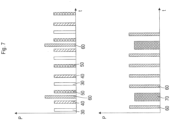
- Fig. 7 now shows exemplary pulse sequences such as those generated by a plasma generator via the switching units 12a, 12b Fig. 3 are delivered, with the two representations arranged one above the other showing the output at different switching units 12a, 12b of the plasma generator.
- the power requirement is to deliver pulses 30, 40, 50 with the same pulse duration, period length between the same pulses and the same power, which go, for example, to the three plasma units 3a to 3c in which the same processes are running at the same time.
- pulses 60 and 70 should also be generated for the plasma units 3d and 3e with different pulse durations, pulse periods and powers, with each pulse 70 temporally overlapping one of the pulses 60.
- the requirements of the plasma units 3d and 3e do not allow any shifts.
- the control unit has now found a division of the pulses in which the switching unit 12a primarily outputs the pulses 30, 40, 50, while the switching unit 12b primarily outputs the pulses 60 and 70.
- the switching unit 12b since the switching unit 12b is not allowed to shift the pulses 60 and 70, but there is an overlap in the requirement every time the pulse 70 is to be output, at the time of outputting the pulse 70 via the switching unit 12b, the required pulse 60 is transmitted via the switching unit 12a issued.
- Fig. 7 This is possible without shifting pulses 30, 40 and 50.
- space can also be created between the pulses 30, 40 and/or 50 in order to accommodate the pulse 60, provided that the requirements of the plasma units 3a to 3c do not conflict with this.
- the plasma generator 5 offers according to Fig. 3 great flexibility in terms of creating pulse sequences to meet the performance requirements of a large number of plasma units, taking into account the respective requirements. Further special pulse management variants will now be explained in more detail below.
- FIG. 9(A) and (B) demonstrate this concept using a system with two chambers (channels), where Fig. 9(A) a pulse request and Fig. 9(B) represents a corresponding pulse output.
- Fig. 9(A) a pulse request
- Fig. 9(B) represents a corresponding pulse output.
- the third and fourth requested pulses 30 and 40 each overlap, with the third pulses having the pulse 30 start before the pulse 40 and the fourth pulses having the pulse 40 starting before the pulse 30.
- pulse 30 is output first, followed by pulse 40.
- pulse 40 is output first, followed by pulse 30.
- the fourth pulse 40 is the same time compared to its requirement profile pushed back, like the third pulse was pushed back, so that the pause time between the third and fourth pulse does not fall below the requested pause time (minimum pause time).
- the displacement of one pulse therefore entails a displacement of subsequent pulses.
- An advantage of this approach is that it is not necessary to subtract the resulting wait time of the subordinate pulse from the pause time. This prevents unwanted feedback.
- this approach can lead to an increase in the pulse-off time over time, and therefore a reduced power output.
- various measures are possible, such as: an extension of the overall process in the affected chambers corresponding to the moving average. Further exemplary measures are explained below.
- Pulse ⁇ Out of ⁇ Time Pulse X set Pulse ⁇ Out of ⁇ Time Pulse X ⁇ Correction value
- the correction value can be set accordingly.
- 2% for example, with a set pulse-off time of 50 ⁇ s, a correction value of 1 ⁇ s can be entered. This is then permanently used during the process.
- X is a random value in % between 0% and the set correction value. This is permanently set and used during the process.
- a correction value is determined based on a determined pulse-off time extension.
- the pulse-off time extension is multiplied by a proportional factor K.
- FIG. 10(A) and (B) demonstrate this concept using a system with two chambers (channels), where Fig. 10(A) a pulse request and Fig. 10 (B) represents a corresponding pulse output.
- Fig. 10(A) a pulse request
- Fig. 10 (B) represents a corresponding pulse output.
- the third and fourth requested pulses 30 and 40 each overlap.
- pulse 30 has the higher priority, so that it is always output as requested, as in Fig. 10(B) can be recognized.
- the third and fourth pulses 40 are output in shorter form. With the third pulse 40, the beginning is drawn behind the end of the pulse 30, while the end is retained according to the requirement profile. At the fourth pulse 40, the pulse begins as requested, but ends earlier, in particular before the request time (and the output) of the overlapping requested pulse 30.
- the corresponding rules can be a. until d. be supplemented with the following rule. e. Based on the in d. certain pulse failure sum, the number of failed pulses is output at the end of the control pulse sequence.
- shifting the start/end of the pulse can be given priority over a pulse increase, so that an attempt is first made to compensate for the missing portion of the pulse by shifting it and only then is the remaining portion (if fully possible) compensated for by increasing the pulse.
- the priority can also be set the other way around or a weighting can be set.
- the plasma generators can be used for a wide variety of plasma units and the number of plasma units to be supplied by a plasma generator can also differ from the number shown.
- the switching units 12a, 12b it is also not necessary for the switching units 12a, 12b to be connected to all plasma units 3a to 3e.
- the switching unit 12a, 12b it would also be conceivable that only plasma units 3a to 3c are connected to the switching unit 12a and the plasma units 3c to 3e are connected to the switching unit 12b, so that only the plasma units 3c can be controlled by both. This would reduce flexibility but still allow at least one of the plasma units to be powered via two switching units to resolve possible conflicts when creating a pulse train.
Landscapes
- Physics & Mathematics (AREA)
- Engineering & Computer Science (AREA)
- Plasma & Fusion (AREA)
- Chemical & Material Sciences (AREA)
- Analytical Chemistry (AREA)
- Spectroscopy & Molecular Physics (AREA)
- Electromagnetism (AREA)
- Plasma Technology (AREA)
- Chemical Vapour Deposition (AREA)
- Drying Of Semiconductors (AREA)
Claims (15)
- Générateur de plasma (5) pour la fourniture pulsée d'énergie électrique à une fréquence d'au moins 40 KHz à au moins deux chambres de traitement (3a - 3e), le générateur de plasma (5) comprenant les éléments suivants :une unité de commande (14) configurée pour recevoir et évaluer des données de traitement concernant des traitements dans les au moins deux chambres de traitement (3a - 3e) ;une alimentation électrique contrôlable (10, 10a) ayant une sortie, l'alimentation électrique contrôlable étant configurée pour fournir en sortie un courant continu ayant une tension et/ou une intensité prédéterminée à sa sortie en réponse à un signal de commande provenant de l'unité de commande (14) ; etune unité de commutation (12, 12a) ayant une première entrée connectée à la sortie de l'alimentation électrique (10, 10a) et ayant au moins deux sorties d'unité de commutation pour une connexion respective à l'une des au moins deux chambres de traitement (3a - 3e) ;dans lequel l'unité de commutation (12, 12a) est configurée pour former un courant alternatif avec une fréquence prédéterminée d'au moins 40 KHz comme signal de sortie à partir d'un courant continu à l'entrée et pour fournir sélectivement en sortie le signal de sortie sous forme d'impulsion pendant une durée d'impulsion prédéterminée à l'une des sorties de l'unité de commutation en réponse à un signal de commande provenant de l'unité de commande (14) ;dans lequel l'unité de commande (14) est configurée pour coordonner des besoins en énergie des au moins deux chambres de traitement (3a - 3e) et pour commander l'alimentation électrique (10, 10a) et l'unité de commutation (12, 12a) de sorte que essentiellement la puissance correspondant aux besoins en énergie soit mise à disposition sous forme d'impulsions sur une période de temps au niveau des sorties respectives de l'unité de commutation communiquant avec les chambres de traitement (3a - 3e), dans lequel les impulsions des chambres de traitement respectives (3a - 3e) sont décalées dans le temps les unes par rapport aux autres de sorte que les chambres de traitement puissent fonctionner en même temps ; etdans lequel l'unité de commande (14) est configurée pour décaler des impulsions ou des parties de celles-ci dans le temps par rapport aux besoins en énergie si les besoins en énergie conduiraient à un chevauchement des impulsions au niveau de différentes sorties, d'une unité de communication respective, dans lequel un décalage dans le temps respectif est sélectionné de sorte que l'énergie fournie au niveau des sorties respectives corresponde essentiellement aux besoins en énergie dans le temps.
- Générateur de plasma (5) selon la revendication 1, dans lequel l'unité de commande (14) comporte un nombre de contrôleurs (16a - 16e) correspondant au nombre d'unités de traitement (3a - 3e) à connecter à l'unité de commutation (12, 12a), chaque contrôleur (16a - 16e) étant configuré pour recevoir des données de traitement concernant des traitements dans l'une respective des chambres de traitement des unités de traitement (3a - 3e), dans lequel chaque contrôleur (16a - 16e) est connecté à l'alimentation électrique (10, 10a) et/ou à l'unité de commutation (12, 12a) pour le commander en réponse aux données de traitement reçues.
- Générateur de plasma (5) selon la revendication 1 ou 2, comprenant en outre au moins une unité de suppression d'arc (18), qui est configurée pour recevoir des données de traitement courantes concernant des traitements dans les au moins deux chambres de traitement et des données courantes de l'alimentation électrique (10, 10a) et/ou de l'unité de commutation (12, 12a) et pour les évaluer en temps réel afin de détecter un arc ou un arc imminent, dans lequel l'unité de suppression d'arc (18) est en communication avec l'alimentation électrique (10, 10a) et/ou avec l'unité de commutation (12, 12a) afin de les commander, si nécessaire, en réponse à la détection d'un arc ou d'un arc imminent, dans lequel l'unité de suppression d'arc (18) fait de préférence partie de l'unité de commande (14).
- Générateur de plasma (5) selon la revendication 2 ou 3, dans lequel les contrôleurs (16a - 16e) et/ou l'au moins une unité de suppression d'arc (18) sont conçus sous forme de modules logiciels séparés qui peuvent être exécutés sur un processeur commun ou sur des processeurs séparés du générateur de plasma.
- Générateur de plasma (5) selon l'une quelconque des revendications précédentes, dans lequel l'unité de commutation (12, 12a) présente au moins une troisième sortie de l'unité de commutation qui est configurée pour être connectée à au moins une chambre de traitement supplémentaire (3a - 3e) ou à un absorbeur (20), et dans lequel l'unité de commutation (12, 12a) est configurée pour, en réponse à un signal de commande entrant provenant de l'unité de commande (14), appliquer sélectivement le signal de sortie sous forme d'impulsion pendant une durée d'impulsion prédéterminée à l'une respective des sorties de l'unité de commutation.
- Générateur de plasma (5) selon l'une quelconque des revendications précédentes, dans lequel l'unité de commande (14) est configurée de sorte qu'elle coordonne la somme de la durée d'impulsion et d'une pause d'impulsion correspondante au niveau des sorties respectives de l'unité de commutation (12, 12a) de sorte que la somme soit la même pour chaque sortie de l'unité de commutation ou que la somme au niveau de l'une des sorties de l'unité de commutation soit multiple de la somme au niveau d'une autre sortie de l'unité de commutation.
- Générateur de plasma (5) selon l'une quelconque des revendications précédentes, dans lequel l'unité de commande (14) est configurée de sorte qu'elle :divise des impulsions individuelles en deux impulsions distinctes en fonction des besoins en énergie et les décale dans le temps si les besoins en énergie conduiraient à un chevauchement des impulsions au niveau de différentes sorties d'une unité de commande respective (14), dans lequel une division de l'impulsion et un décalage temporel respectifs sont choisis de sorte que l'énergie fournie en sortie au niveau des sorties respectives corresponde sensiblement aux besoins d'énergie dans le temps ; et/oupuisse modifier au moins un des paramètres suivants d'une impulsion : une position d'une impulsion dans un train d'impulsions, une division d'une impulsion en impulsions partielles, une durée d'impulsion et une amplitude d'une impulsion si des besoins en énergie courants conduiraient à un chevauchement des impulsions au niveau de différentes sorties d'une unité de commutation respective (12, 12a).
- Générateur de plasma (5) selon l'une quelconque des revendications précédentes pour la fourniture pulsée d'énergie électrique à une fréquence d'au moins 40 KHz à au moins trois chambres de traitement (3a - 3e), le générateur de plasma (5) comprenant en outre les éléments suivants :une alimentation électrique contrôlable supplémentaire (10b) ayant une sortie, l'alimentation électrique contrôlable étant configurée pour fournir en sortie un courant continu ayant une tension et/ou une intensité prédéterminée au niveau de sa sortie en réponse à un signal de commande provenant de l'unité de commande (14) ; etune unité de commutation supplémentaire (12b) ayant une entrée de puissance connectée à la sortie de l'alimentation électrique supplémentaire (10b) et ayant au moins trois sorties d'unité de commutation pour une connexion respective à l'une des au moins trois chambres de traitement ;dans lequel l'unité de commutation supplémentaire (12b) est configurée pour former un courant alternatif à une fréquence prédéterminée d'au moins 40 KHz comme signal de sortie à partir d'un courant continu à l'entrée et pour fournir sélectivement en sortie le signal de sortie sous forme d'une impulsion ayant une durée d'impulsion prédéterminée à l'une des sorties de l'unité de commutation en réponse à un signal de commande provenant de l'unité de commande (14) ;dans lequel l'unité de commande (14) est configurée pour coordonner des besoins en énergie des au moins trois chambres de traitement et pour commander les alimentations électriques (10a, 10b) et les unités de commutation (12a, 12b) de sorte que, au niveau d'une sortie respective parmi les sorties d'unité de communication, en communication avec les chambres de traitement, la puissance correspondant aux besoins en énergie soit sensiblement disponible sous forme d'impulsions dans le temps, dans lequel les impulsions fournies par une unité de commutation (12a, 12b) pour les chambres de traitement sont décalées dans le temps les unes par rapport aux autres, alors que les impulsions des deux unités de commutation (12a, 12b) peuvent se chevaucher, dans lequel les alimentations électriques (10a, 10b) ont de préférence des puissances nominales différentes.
- Dispositif de traitement au plasma (1) comprenant au moins deux chambres de traitement séparées, dans chacune desquelles un plasma peut être généré et un générateur de plasma (5) selon l'une des revendications précédentes, dans lequel les chambres de traitement sont connectées chacune à l'une des sorties de l'unité de commutation de la ou des unités de commutation (12, 12a, 12b).
- Dispositif de traitement au plasma (1) selon la revendication 9, comprenant au moins trois chambres de traitement, dans lequel l'unité (les unités) de commutation (12, 12a, 12b) du générateur de plasma (5) comprend (comprennent) au moins trois sorties de l'unité de commutation et dans lequel les chambres de traitement sont connectées chacune à l'une des sorties de l'unité de commutation.
- Procédé pour la fourniture pulsée d'énergie électrique à une fréquence prédéterminée d'au moins 40 KHz à au moins deux chambres de traitement séparées, le procédé comprenant les étapes suivantes :la fourniture d'un courant continu ayant une tension et/ou une amplitude prédéterminée à une entrée d'une unité de commutation (12, 12a) en réponse à un signal de commande provenant d'une unité de commande (14) ;la formation, à partir du courant continu, d'un signal de sortie de courant alternatif à une fréquence prédéterminée d'au moins 40 kHz dans l'unité de commutation (12, 12a) et, en réponse à un signal de commande provenant de l'unité de commande (14), la fourniture sélective, en sortie, du signal de sortie de courant alternatif sous la forme d'une impulsion au niveau de l'une d'au moins deux sorties d'unité de commutation de l'unité de commutation (12, 12a), dont chacune est connectée à l'une des au moins deux chambres de traitement séparées ;dans lequel l'unité de commande (14), en réponse aux besoins en énergie des au moins deux chambres de traitement et en réponse aux données de traitement concernant des traitements dans les au moins deux chambres de traitement, génère des signaux de commande pour fournir les signaux de courant continu et de commande pour fournir sélectivement en sortie le signal de sortie de courant alternatif, dans lequel les signaux de commande sont coordonnés de sorte que, au niveau des sorties de l'unité de commutation respectives, qui sont connectées aux chambres de traitement, la puissance correspondant sensiblement aux besoins en énergie soit rendue disponible sous forme d'impulsions dans le temps, dans lequel les impulsions pour les chambres de traitement sont décalées dans le temps les unes par rapport aux autres, pendant que les chambres de traitement fonctionnent en même temps ; etdans lequel l'unité de commande modifie au moins l'un des paramètres suivants d'une impulsion : une position d'une impulsion dans un train d'impulsions, une division d'une impulsion en impulsions partielles, une durée d'impulsion et une amplitude d'une impulsion si des besoins en énergie courants conduiraient à un chevauchement des impulsions sur différentes sorties.
- Procédé selon la revendication 11, dans lequel l'unité de commande (14) effectue un réglage conformément à des règles fixes prédéterminées ou des règles pouvant être fixées par un opérateur, ou
dans lequel l'unité de commande (14) compare la puissance de sortie en impulsions par chambre de traitement sur une période de temps à la puissance demandée sur la période de temps et modifie automatiquement au moins un paramètre d'une impulsion sur la base de la comparaison. - Procédé selon l'une quelconque des revendications 11 ou 12, dans lequel l'énergie électrique est fournie à au moins trois chambres de traitement, dans lequel l'unité de commutation (12a, 12b) a au moins trois sorties d'unité de commutation, dont chacune est connectée à l'une des au moins trois chambres de traitement ; et
dans lequel l'unité de commande (14), en réponse aux besoins en énergie des au moins trois chambres de traitement et en réponse aux données de traitement concernant des traitement dans les au moins trois chambres de traitement, génère des signaux de commande pour fournir des signaux de courant continu et de commande pour fournir sélectivement, en sortie, le signal de sortie de courant alternatif, dans lequel les signaux de commande sont coordonnés de sorte que, au niveau des sorties de l'unité de commutation respectives, qui sont connectées aux chambres de traitement, la puissance correspondant aux besoins en énergie soit sensiblement mise à disposition dans le temps sous forme d'impulsions, dans lequel les impulsions pour les chambres de traitement sont décalées dans le temps les unes par rapport aux autres, alors que les chambres de traitement fonctionnent en même temps. - Procédé selon l'une des revendications 11 à 13, dans lequel l'unité de commande (14) coordonne la somme de la durée d'impulsion et d'une pause d'impulsion correspondante au niveau des sorties respectives de l'unité de commutation d'une unité de communication (12, 12a) de sorte que la somme soit la même pour chaque sortie de l'unité de commutation ou que la somme au niveau de l'une des sorties de l'unité de commutation soit multiple de la somme au niveau d'une autre sortie de l'unité de commutation.
- Procédé selon l'une des revendications 11 à 13 pour la fourniture pulsée d'énergie électrique à une fréquence prédéterminée d'au moins 40 KHz à au moins trois chambres de traitement, le procédé comprenant les étapes supplémentaires suivantes :la fourniture d'un courant continu ayant une tension et/ou une amplitude prédéterminée à une entrée d'une unité de commutation supplémentaire (12b) en réponse à un signal de commande provenant de l'unité de commande (14) ;la formation, à partir du courant continu, d'un signal de sortie de courant alternatif ayant une fréquence prédéterminée d'au moins 40 KHz dans l'unité de commutation supplémentaire (12b) et, en réponse à un signal de commande provenant de l'unité de commande (14), la fourniture sélective en sortie du signal de sortie de courant alternatif sous forme d'une impulsion à l'une des sorties des au moins trois unités de commutation de la deuxième unité de commutation (12b), dont chacune est connectée à l'une des au moins trois chambres de traitement ;dans lequel l'unité de commande (14), en réponse aux besoins en énergie des au moins trois chambres de traitement et en réponse aux données de traitement concernant des traitements dans les au moins trois chambres de traitement, génère des signaux de commande pour fournir les signaux de courant continu et de commande pour fournir sélectivement en sortie le signal de sortie de courant alternatif, dans lequel les signaux de commande sont coordonnés de sorte que, au niveau des sorties de l'unité de commutation respectives, qui sont connectées aux chambres de traitement, la puissance correspondant sensiblement aux besoins en énergie soit rendue disponible sous forme d'impulsions dans le temps, dans lequel les impulsions qui sont fournies par une unité respective parmi les unités de commutation (12a, 12b) sont décalées dans le temps les unes par rapport aux autres, alors que les impulsions des deux unités de commutation (12a, 12b) peuvent se chevaucher dans le temps.
Applications Claiming Priority (4)
| Application Number | Priority Date | Filing Date | Title |
|---|---|---|---|
| DE102017205582 | 2017-03-31 | ||
| DE102018204585.2A DE102018204585A1 (de) | 2017-03-31 | 2018-03-26 | Plasmagenerator, Plasma-Behandlungsvorrichtung und Verfahren zum gepulsten Bereitstellen von elektrischer Leistung |
| EP18715016.4A EP3602601B1 (fr) | 2017-03-31 | 2018-03-29 | Générateur de plasma, dispositif de traitement par plasma et procédé servant à fournir par impulsions une puissance électrique |
| PCT/EP2018/058193 WO2018178289A1 (fr) | 2017-03-31 | 2018-03-29 | Générateur de plasma, dispositif de traitement par plasma et procédé servant à fournir par impulsions une puissance électrique |
Related Parent Applications (1)
| Application Number | Title | Priority Date | Filing Date |
|---|---|---|---|
| EP18715016.4A Division EP3602601B1 (fr) | 2017-03-31 | 2018-03-29 | Générateur de plasma, dispositif de traitement par plasma et procédé servant à fournir par impulsions une puissance électrique |
Publications (3)
| Publication Number | Publication Date |
|---|---|
| EP3879558A1 EP3879558A1 (fr) | 2021-09-15 |
| EP3879558B1 true EP3879558B1 (fr) | 2023-11-22 |
| EP3879558C0 EP3879558C0 (fr) | 2023-11-22 |
Family
ID=63524659
Family Applications (2)
| Application Number | Title | Priority Date | Filing Date |
|---|---|---|---|
| EP21171624.6A Active EP3879558B1 (fr) | 2017-03-31 | 2018-03-29 | Générateur de plasma, dispositif de traitement au plasma et procédé de fourniture pulsée de l'énergie électrique |
| EP18715016.4A Active EP3602601B1 (fr) | 2017-03-31 | 2018-03-29 | Générateur de plasma, dispositif de traitement par plasma et procédé servant à fournir par impulsions une puissance électrique |
Family Applications After (1)
| Application Number | Title | Priority Date | Filing Date |
|---|---|---|---|
| EP18715016.4A Active EP3602601B1 (fr) | 2017-03-31 | 2018-03-29 | Générateur de plasma, dispositif de traitement par plasma et procédé servant à fournir par impulsions une puissance électrique |
Country Status (9)
| Country | Link |
|---|---|
| US (3) | US11355316B2 (fr) |
| EP (2) | EP3879558B1 (fr) |
| KR (2) | KR102838071B1 (fr) |
| CN (2) | CN114709126B (fr) |
| DE (1) | DE102018204585A1 (fr) |
| MY (1) | MY202814A (fr) |
| PL (2) | PL3879558T3 (fr) |
| TW (1) | TWI762613B (fr) |
| WO (1) | WO2018178289A1 (fr) |
Families Citing this family (6)
| Publication number | Priority date | Publication date | Assignee | Title |
|---|---|---|---|---|
| DE102018204585A1 (de) * | 2017-03-31 | 2018-10-04 | centrotherm international AG | Plasmagenerator, Plasma-Behandlungsvorrichtung und Verfahren zum gepulsten Bereitstellen von elektrischer Leistung |
| DE102018216969A1 (de) * | 2018-10-03 | 2020-04-09 | centrotherm international AG | Plasma-Behandlungsvorrichtung und Verfahren zum Ausgeben von Pulsen elektischer Leistung an wenigstens eine Prozesskammer |
| DE102018132700A1 (de) | 2018-12-18 | 2020-06-18 | Krones Ag | Vorrichtung und Verfahren zum Beschichten und insbesondere Plasmabeschichten von Behältnissen |
| CN114424447A (zh) * | 2019-07-29 | 2022-04-29 | 先进工程解决方案全球控股私人有限公司 | 用于多个负载的脉冲驱动的具有通道偏移的多路复用功率发生器输出 |
| DE102022131435A1 (de) | 2022-11-28 | 2024-05-29 | TRUMPF Hüttinger GmbH + Co. KG | Vorrichtung zur Erzeugung einer Plasmaflamme, Plasmaerzeugungseinrichtung, Hochtemperaturprozessanlage und entsprechendes Betriebsverfahren |
| CN116095936B (zh) * | 2023-02-13 | 2025-12-02 | 南京工业大学 | 维持不同等离子体放电阶段脉冲功率调控装置和方法 |
Family Cites Families (55)
| Publication number | Priority date | Publication date | Assignee | Title |
|---|---|---|---|---|
| US3500118A (en) * | 1967-07-17 | 1970-03-10 | Gen Electric | Electrodeless gaseous electric discharge devices utilizing ferrite cores |
| US3657591A (en) * | 1970-06-26 | 1972-04-18 | Gen Electric | High intensity far u.v. radiation source |
| US3987335A (en) * | 1975-01-20 | 1976-10-19 | General Electric Company | Electrodeless fluorescent lamp bulb RF power energized through magnetic core located partially within gas discharge space |
| US3987334A (en) * | 1975-01-20 | 1976-10-19 | General Electric Company | Integrally ballasted electrodeless fluorescent lamp |
| US4017764A (en) * | 1975-01-20 | 1977-04-12 | General Electric Company | Electrodeless fluorescent lamp having a radio frequency gas discharge excited by a closed loop magnetic core |
| US4048541A (en) * | 1976-06-14 | 1977-09-13 | Solitron Devices, Inc. | Crystal controlled oscillator circuit for illuminating electrodeless fluorescent lamp |
| US4180763A (en) * | 1978-01-25 | 1979-12-25 | General Electric Company | High intensity discharge lamp geometries |
| US4431898A (en) * | 1981-09-01 | 1984-02-14 | The Perkin-Elmer Corporation | Inductively coupled discharge for plasma etching and resist stripping |
| JP2787503B2 (ja) * | 1990-02-26 | 1998-08-20 | 住友重機械工業株式会社 | プラズマ処理装置 |
| JPH08153148A (ja) * | 1994-11-29 | 1996-06-11 | Nippon Telegr & Teleph Corp <Ntt> | アナログニューラルネットワーク学習回路 |
| US6071572A (en) * | 1996-10-15 | 2000-06-06 | Applied Materials, Inc. | Forming tin thin films using remote activated specie generation |
| US6150628A (en) * | 1997-06-26 | 2000-11-21 | Applied Science And Technology, Inc. | Toroidal low-field reactive gas source |
| US7569790B2 (en) * | 1997-06-26 | 2009-08-04 | Mks Instruments, Inc. | Method and apparatus for processing metal bearing gases |
| US6418874B1 (en) * | 2000-05-25 | 2002-07-16 | Applied Materials, Inc. | Toroidal plasma source for plasma processing |
| US6893907B2 (en) * | 2002-06-05 | 2005-05-17 | Applied Materials, Inc. | Fabrication of silicon-on-insulator structure using plasma immersion ion implantation |
| US7223676B2 (en) * | 2002-06-05 | 2007-05-29 | Applied Materials, Inc. | Very low temperature CVD process with independently variable conformality, stress and composition of the CVD layer |
| US7137354B2 (en) * | 2000-08-11 | 2006-11-21 | Applied Materials, Inc. | Plasma immersion ion implantation apparatus including a plasma source having low dissociation and low minimum plasma voltage |
| US6855906B2 (en) * | 2001-10-16 | 2005-02-15 | Adam Alexander Brailove | Induction plasma reactor |
| SE0302045D0 (sv) * | 2003-07-10 | 2003-07-10 | Chemfilt R & D Ab | Work piece processing by pulsed electric discharges in solid-gas plasmas |
| SE532505C2 (sv) * | 2007-12-12 | 2010-02-09 | Plasmatrix Materials Ab | Förfarande för plasmaaktiverad kemisk ångdeponering och plasmasönderdelningsenhet |
| PL2259662T3 (pl) * | 2008-03-26 | 2019-10-31 | Kyosan Electric Mfg | Urządzenie wygaszające nietypowe wyładowanie do przyrządu próżniowego |
| US9287086B2 (en) * | 2010-04-26 | 2016-03-15 | Advanced Energy Industries, Inc. | System, method and apparatus for controlling ion energy distribution |
| US8771538B2 (en) * | 2009-11-18 | 2014-07-08 | Applied Materials, Inc. | Plasma source design |
| US8742665B2 (en) * | 2009-11-18 | 2014-06-03 | Applied Materials, Inc. | Plasma source design |
| US8880227B2 (en) * | 2010-05-27 | 2014-11-04 | Applied Materials, Inc. | Component temperature control by coolant flow control and heater duty cycle control |
| DE102010031568B4 (de) * | 2010-07-20 | 2014-12-11 | TRUMPF Hüttinger GmbH + Co. KG | Arclöschanordnung und Verfahren zum Löschen von Arcs |
| US20130059448A1 (en) * | 2011-09-07 | 2013-03-07 | Lam Research Corporation | Pulsed Plasma Chamber in Dual Chamber Configuration |
| US9065426B2 (en) * | 2011-11-03 | 2015-06-23 | Advanced Energy Industries, Inc. | High frequency solid state switching for impedance matching |
| DE102011009693A1 (de) * | 2011-01-28 | 2012-08-02 | Centrotherm Thermal Solutions Gmbh & Co. Kg | Kühlmodul und Vorrichtung zum thermischen Behandeln von Substraten |
| US8884525B2 (en) * | 2011-03-22 | 2014-11-11 | Advanced Energy Industries, Inc. | Remote plasma source generating a disc-shaped plasma |
| US8952765B2 (en) * | 2012-03-23 | 2015-02-10 | Mks Instruments, Inc. | System and methods of bimodal automatic power and frequency tuning of RF generators |
| US9210790B2 (en) * | 2012-08-28 | 2015-12-08 | Advanced Energy Industries, Inc. | Systems and methods for calibrating a switched mode ion energy distribution system |
| US20140272108A1 (en) * | 2013-03-15 | 2014-09-18 | Plasmability, Llc | Toroidal Plasma Processing Apparatus |
| US9336995B2 (en) * | 2013-04-26 | 2016-05-10 | Mks Instruments, Inc. | Multiple radio frequency power supply control of frequency and phase |
| US9341610B1 (en) * | 2013-08-29 | 2016-05-17 | The Boeing Company | Electrical arc trigger systems, methods, and apparatuses |
| US9514917B1 (en) * | 2013-08-29 | 2016-12-06 | The Boeing Company | Controlled-energy electrical arc systems, methods, and apparatuses |
| LT3187028T (lt) * | 2014-10-13 | 2020-01-27 | Tae Technologies, Inc. | Kompaktiškų torų suliejimo ir suspaudimo sistema |
| KR20160049628A (ko) * | 2014-10-28 | 2016-05-10 | 최도현 | 듀얼 플라즈마 발생기, 플라즈마 처리 시스템 및 방법 |
| KR102091673B1 (ko) | 2015-02-06 | 2020-03-23 | 주식회사 원익아이피에스 | 플라즈마 전력 공급 장치 |
| TWI670749B (zh) * | 2015-03-13 | 2019-09-01 | 美商應用材料股份有限公司 | 耦接至工藝腔室的電漿源 |
| DE102015004419A1 (de) | 2015-04-02 | 2016-10-06 | Centrotherm Photovoltaics Ag | Waferboot und Plasma-Behandlungsvorrichtung für Wafer |
| KR20180000721A (ko) * | 2015-05-21 | 2018-01-03 | 플라즈마빌리티, 엘엘씨 | 성형된 피처리물 지지체를 갖는 토로이달 플라즈마 처리 장치 |
| US9721758B2 (en) * | 2015-07-13 | 2017-08-01 | Mks Instruments, Inc. | Unified RF power delivery single input, multiple output control for continuous and pulse mode operation |
| US10395895B2 (en) * | 2015-08-27 | 2019-08-27 | Mks Instruments, Inc. | Feedback control by RF waveform tailoring for ion energy distribution |
| WO2017050772A1 (fr) * | 2015-09-23 | 2017-03-30 | Centrotherm Photovoltaics Ag | Procédé et dispositif de passivation de défauts dans des substrats semi-conducteurs |
| KR102092213B1 (ko) * | 2016-03-23 | 2020-03-23 | 베이징 나우라 마이크로일렉트로닉스 이큅먼트 씨오., 엘티디. | 임피던스 매칭 시스템, 임피던스 매칭 방법 및 반도체 공정장비 |
| US10187032B2 (en) * | 2016-06-17 | 2019-01-22 | Lam Research Corporation | Combiner and distributor for adjusting impedances or power across multiple plasma processing stations |
| US10777385B2 (en) * | 2016-07-14 | 2020-09-15 | Tokyo Electron Limited | Method for RF power distribution in a multi-zone electrode array |
| UA126673C2 (uk) * | 2016-11-15 | 2023-01-11 | Тае Текнолоджіз, Інк. | Системи і способи поліпшеної підтримки високоефективної конфігурації з оберненим полем і нагрівання електронів за допомогою вищих гармонік швидких хвиль у високоефективній конфігурації з оберненим полем |
| DE102018204585A1 (de) * | 2017-03-31 | 2018-10-04 | centrotherm international AG | Plasmagenerator, Plasma-Behandlungsvorrichtung und Verfahren zum gepulsten Bereitstellen von elektrischer Leistung |
| DE102017206612A1 (de) * | 2017-04-19 | 2018-10-25 | Centrotherm Photovoltaics Ag | Verfahren und Vorrichtung zum Ausbilden einer Schicht auf einem Halbleitersubstrat sowie Halbleitersubstrat |
| EP3396698A1 (fr) * | 2017-04-27 | 2018-10-31 | TRUMPF Hüttinger GmbH + Co. KG | Unité de conversion de puissance, équipement de traitement au plasma et procédé de commande de plusieurs traitements au plasma |
| US10991550B2 (en) * | 2018-09-04 | 2021-04-27 | Lam Research Corporation | Modular recipe controlled calibration (MRCC) apparatus used to balance plasma in multiple station system |
| WO2022146649A1 (fr) * | 2020-12-28 | 2022-07-07 | Mattson Technology, Inc. | Source de plasma icp-ccp hybride commandée directement |
| TWI829156B (zh) * | 2021-05-25 | 2024-01-11 | 大陸商北京屹唐半導體科技股份有限公司 | 電漿源陣列、電漿處理設備、電漿處理系統以及用於在電漿處理設備中加工工件的方法 |
-
2018
- 2018-03-26 DE DE102018204585.2A patent/DE102018204585A1/de active Pending
- 2018-03-29 WO PCT/EP2018/058193 patent/WO2018178289A1/fr not_active Ceased
- 2018-03-29 KR KR1020237034119A patent/KR102838071B1/ko active Active
- 2018-03-29 EP EP21171624.6A patent/EP3879558B1/fr active Active
- 2018-03-29 MY MYPI2019005636A patent/MY202814A/en unknown
- 2018-03-29 CN CN202210365643.0A patent/CN114709126B/zh active Active
- 2018-03-29 PL PL21171624.6T patent/PL3879558T3/pl unknown
- 2018-03-29 CN CN201880023582.1A patent/CN110494949B/zh not_active Expired - Fee Related
- 2018-03-29 PL PL18715016T patent/PL3602601T3/pl unknown
- 2018-03-29 EP EP18715016.4A patent/EP3602601B1/fr active Active
- 2018-03-29 KR KR1020197032047A patent/KR102588542B1/ko active Active
- 2018-03-29 US US16/498,728 patent/US11355316B2/en active Active
- 2018-03-30 TW TW107111399A patent/TWI762613B/zh active
-
2022
- 2022-04-28 US US17/731,774 patent/US12087544B2/en active Active
-
2024
- 2024-09-09 US US18/828,021 patent/US20240429026A1/en active Pending
Also Published As
| Publication number | Publication date |
|---|---|
| EP3602601A1 (fr) | 2020-02-05 |
| US20210111001A1 (en) | 2021-04-15 |
| EP3602601B1 (fr) | 2021-05-05 |
| TWI762613B (zh) | 2022-05-01 |
| KR20230142821A (ko) | 2023-10-11 |
| KR102588542B1 (ko) | 2023-10-11 |
| KR102838071B1 (ko) | 2025-07-23 |
| CN110494949B (zh) | 2022-04-29 |
| US11355316B2 (en) | 2022-06-07 |
| CN114709126B (zh) | 2025-04-11 |
| PL3602601T3 (pl) | 2021-10-25 |
| US20240429026A1 (en) | 2024-12-26 |
| CN114709126A (zh) | 2022-07-05 |
| DE102018204585A1 (de) | 2018-10-04 |
| PL3879558T3 (pl) | 2024-03-25 |
| US12087544B2 (en) | 2024-09-10 |
| EP3879558A1 (fr) | 2021-09-15 |
| EP3879558C0 (fr) | 2023-11-22 |
| KR20190130019A (ko) | 2019-11-20 |
| WO2018178289A1 (fr) | 2018-10-04 |
| CN110494949A (zh) | 2019-11-22 |
| MY202814A (en) | 2024-05-23 |
| TW201904358A (zh) | 2019-01-16 |
| US20220254609A1 (en) | 2022-08-11 |
Similar Documents
| Publication | Publication Date | Title |
|---|---|---|
| EP3602601B1 (fr) | Générateur de plasma, dispositif de traitement par plasma et procédé servant à fournir par impulsions une puissance électrique | |
| EP3433126B1 (fr) | Procédé d'exploitation d'un réseau électrique | |
| EP1927183B1 (fr) | Procede pour commander un convertisseur de courant polyphase au moyen d'accumulateurs d'energie repartis | |
| DE102016203044B4 (de) | Verfahren und vorrichtung zur rippelspannungsreduktion in einem fahrzeugbordnetz | |
| DE202018006714U1 (de) | Leistungswandlereinheit, Plasmabearbeitungseinrichtung und Steuereinrichtung zur Steuerung mehrerer Plasmaprozesse | |
| DE202018006711U1 (de) | Leistungswandlereinheit, Plasmabearbeitungseinrichtung und Steuereinrichtung zur Steuerung mehrerer Plasmaprozesse | |
| DE3118554A1 (de) | Stromversorgungsschaltung | |
| DE102008026544A1 (de) | Steuerung von zwei Motoren mit einem einzigen Prozessor | |
| EP2727236B1 (fr) | Procédé de commande d'un onduleur d'un outil électrique et outil électrique | |
| DE2446635A1 (de) | Wechselrichteranordnung mit zwei dreiphasigen steuerbaren wechselrichtern | |
| DE2824326A1 (de) | Stromversorgung fuer elektrische bearbeitung | |
| DE3414102A1 (de) | Steuergeraet fuer einen stromwechselrichter | |
| EP0716561B1 (fr) | Appareil à rayons X comportant une unité pour l'alimentation en puissance d'un tube à rayons X | |
| DE19709767C1 (de) | Verfahren zum Ansteuern mehrerer Schaltendstufen, Ansteuereinrichtung und Leistungsverstärker | |
| EP3672053A1 (fr) | Procédé de commande pour un convertisseur à résonance série en pont actif double et convertisseur à résonance série en pont actif double selon ledit procédé | |
| DE102013213266A1 (de) | Energiespeichersystem mit erhöhter abgegebener elektrischer Leistung | |
| DE102007059380B3 (de) | Verfahren zur Minimierung von Rippelströmen | |
| EP3935921B1 (fr) | Moyens de commande et/ou de régulation, circuit et procédé pour la commande de diodes électroluminescentes dans un réseau de diodes électroluminescentes | |
| DE102017213194A1 (de) | Wandlervorrichtung zum Wandeln einer elektrischen Gleichspannung, Verfahren und Steuereinrichtung zum Steuern einer Wandlervorrichtung zum Wandeln einer elektrischen Gleichspannung | |
| EP1053588B1 (fr) | Procedes pour etablir des instructions de reglage pour redresseurs | |
| EP3619804B1 (fr) | Procédé de commande d'un convertisseur de courant, dispositif de commande pour un convertisseur de courant et convertisseur de courant | |
| DE102013200844A1 (de) | Hochspannungsimpulsgenerator und Verfahren zum Erzeugen von Hochspannungsimpulsen | |
| EP2928056B1 (fr) | Procédé et dispositif de fonctionnement d'un convertisseur de courant modulaire avec une grande vitesse de commutation ajustable | |
| DE102023210240A1 (de) | Verfahren zum Betreiben mehrerer parallel geschalteter aktiver Gleichrichter | |
| WO2019179748A1 (fr) | Procédé de commande d'un convertisseur à modulation d'impulsions en durée et convertisseur à modulation d'impulsions en durée |
Legal Events
| Date | Code | Title | Description |
|---|---|---|---|
| PUAI | Public reference made under article 153(3) epc to a published international application that has entered the european phase |
Free format text: ORIGINAL CODE: 0009012 |
|
| STAA | Information on the status of an ep patent application or granted ep patent |
Free format text: STATUS: REQUEST FOR EXAMINATION WAS MADE |
|
| 17P | Request for examination filed |
Effective date: 20210430 |
|
| AC | Divisional application: reference to earlier application |
Ref document number: 3602601 Country of ref document: EP Kind code of ref document: P |
|
| AK | Designated contracting states |
Kind code of ref document: A1 Designated state(s): AL AT BE BG CH CY CZ DE DK EE ES FI FR GB GR HR HU IE IS IT LI LT LU LV MC MK MT NL NO PL PT RO RS SE SI SK SM TR |
|
| GRAP | Despatch of communication of intention to grant a patent |
Free format text: ORIGINAL CODE: EPIDOSNIGR1 |
|
| STAA | Information on the status of an ep patent application or granted ep patent |
Free format text: STATUS: GRANT OF PATENT IS INTENDED |
|
| INTG | Intention to grant announced |
Effective date: 20230615 |
|
| GRAS | Grant fee paid |
Free format text: ORIGINAL CODE: EPIDOSNIGR3 |
|
| GRAA | (expected) grant |
Free format text: ORIGINAL CODE: 0009210 |
|
| STAA | Information on the status of an ep patent application or granted ep patent |
Free format text: STATUS: THE PATENT HAS BEEN GRANTED |
|
| AC | Divisional application: reference to earlier application |
Ref document number: 3602601 Country of ref document: EP Kind code of ref document: P |
|
| AK | Designated contracting states |
Kind code of ref document: B1 Designated state(s): AL AT BE BG CH CY CZ DE DK EE ES FI FR GB GR HR HU IE IS IT LI LT LU LV MC MK MT NL NO PL PT RO RS SE SI SK SM TR |
|
| REG | Reference to a national code |
Ref country code: GB Ref legal event code: FG4D Free format text: NOT ENGLISH |
|
| REG | Reference to a national code |
Ref country code: CH Ref legal event code: EP |
|
| REG | Reference to a national code |
Ref country code: DE Ref legal event code: R096 Ref document number: 502018013693 Country of ref document: DE |
|
| REG | Reference to a national code |
Ref country code: IE Ref legal event code: FG4D Free format text: LANGUAGE OF EP DOCUMENT: GERMAN |
|
| U01 | Request for unitary effect filed |
Effective date: 20231219 |
|
| U07 | Unitary effect registered |
Designated state(s): AT BE BG DE DK EE FI FR IT LT LU LV MT NL PT SE SI Effective date: 20240103 |
|
| PG25 | Lapsed in a contracting state [announced via postgrant information from national office to epo] |
Ref country code: GR Free format text: LAPSE BECAUSE OF FAILURE TO SUBMIT A TRANSLATION OF THE DESCRIPTION OR TO PAY THE FEE WITHIN THE PRESCRIBED TIME-LIMIT Effective date: 20240223 |
|
| PG25 | Lapsed in a contracting state [announced via postgrant information from national office to epo] |
Ref country code: IS Free format text: LAPSE BECAUSE OF FAILURE TO SUBMIT A TRANSLATION OF THE DESCRIPTION OR TO PAY THE FEE WITHIN THE PRESCRIBED TIME-LIMIT Effective date: 20240322 |
|
| U20 | Renewal fee for the european patent with unitary effect paid |
Year of fee payment: 7 Effective date: 20240320 |
|
| PG25 | Lapsed in a contracting state [announced via postgrant information from national office to epo] |
Ref country code: ES Free format text: LAPSE BECAUSE OF FAILURE TO SUBMIT A TRANSLATION OF THE DESCRIPTION OR TO PAY THE FEE WITHIN THE PRESCRIBED TIME-LIMIT Effective date: 20231122 |
|
| PG25 | Lapsed in a contracting state [announced via postgrant information from national office to epo] |
Ref country code: IS Free format text: LAPSE BECAUSE OF FAILURE TO SUBMIT A TRANSLATION OF THE DESCRIPTION OR TO PAY THE FEE WITHIN THE PRESCRIBED TIME-LIMIT Effective date: 20240322 Ref country code: GR Free format text: LAPSE BECAUSE OF FAILURE TO SUBMIT A TRANSLATION OF THE DESCRIPTION OR TO PAY THE FEE WITHIN THE PRESCRIBED TIME-LIMIT Effective date: 20240223 Ref country code: ES Free format text: LAPSE BECAUSE OF FAILURE TO SUBMIT A TRANSLATION OF THE DESCRIPTION OR TO PAY THE FEE WITHIN THE PRESCRIBED TIME-LIMIT Effective date: 20231122 |
|
| PG25 | Lapsed in a contracting state [announced via postgrant information from national office to epo] |
Ref country code: RS Free format text: LAPSE BECAUSE OF FAILURE TO SUBMIT A TRANSLATION OF THE DESCRIPTION OR TO PAY THE FEE WITHIN THE PRESCRIBED TIME-LIMIT Effective date: 20231122 Ref country code: NO Free format text: LAPSE BECAUSE OF FAILURE TO SUBMIT A TRANSLATION OF THE DESCRIPTION OR TO PAY THE FEE WITHIN THE PRESCRIBED TIME-LIMIT Effective date: 20240222 Ref country code: HR Free format text: LAPSE BECAUSE OF FAILURE TO SUBMIT A TRANSLATION OF THE DESCRIPTION OR TO PAY THE FEE WITHIN THE PRESCRIBED TIME-LIMIT Effective date: 20231122 |
|
| PG25 | Lapsed in a contracting state [announced via postgrant information from national office to epo] |
Ref country code: CZ Free format text: LAPSE BECAUSE OF FAILURE TO SUBMIT A TRANSLATION OF THE DESCRIPTION OR TO PAY THE FEE WITHIN THE PRESCRIBED TIME-LIMIT Effective date: 20231122 |
|
| PG25 | Lapsed in a contracting state [announced via postgrant information from national office to epo] |
Ref country code: SK Free format text: LAPSE BECAUSE OF FAILURE TO SUBMIT A TRANSLATION OF THE DESCRIPTION OR TO PAY THE FEE WITHIN THE PRESCRIBED TIME-LIMIT Effective date: 20231122 |
|
| PG25 | Lapsed in a contracting state [announced via postgrant information from national office to epo] |
Ref country code: SM Free format text: LAPSE BECAUSE OF FAILURE TO SUBMIT A TRANSLATION OF THE DESCRIPTION OR TO PAY THE FEE WITHIN THE PRESCRIBED TIME-LIMIT Effective date: 20231122 Ref country code: SK Free format text: LAPSE BECAUSE OF FAILURE TO SUBMIT A TRANSLATION OF THE DESCRIPTION OR TO PAY THE FEE WITHIN THE PRESCRIBED TIME-LIMIT Effective date: 20231122 Ref country code: RO Free format text: LAPSE BECAUSE OF FAILURE TO SUBMIT A TRANSLATION OF THE DESCRIPTION OR TO PAY THE FEE WITHIN THE PRESCRIBED TIME-LIMIT Effective date: 20231122 Ref country code: CZ Free format text: LAPSE BECAUSE OF FAILURE TO SUBMIT A TRANSLATION OF THE DESCRIPTION OR TO PAY THE FEE WITHIN THE PRESCRIBED TIME-LIMIT Effective date: 20231122 |
|
| REG | Reference to a national code |
Ref country code: DE Ref legal event code: R097 Ref document number: 502018013693 Country of ref document: DE |
|
| PLBE | No opposition filed within time limit |
Free format text: ORIGINAL CODE: 0009261 |
|
| STAA | Information on the status of an ep patent application or granted ep patent |
Free format text: STATUS: NO OPPOSITION FILED WITHIN TIME LIMIT |
|
| 26N | No opposition filed |
Effective date: 20240823 |
|
| REG | Reference to a national code |
Ref country code: CH Ref legal event code: PL |
|
| PG25 | Lapsed in a contracting state [announced via postgrant information from national office to epo] |
Ref country code: MC Free format text: LAPSE BECAUSE OF FAILURE TO SUBMIT A TRANSLATION OF THE DESCRIPTION OR TO PAY THE FEE WITHIN THE PRESCRIBED TIME-LIMIT Effective date: 20231122 |
|
| GBPC | Gb: european patent ceased through non-payment of renewal fee |
Effective date: 20240329 |
|
| PG25 | Lapsed in a contracting state [announced via postgrant information from national office to epo] |
Ref country code: MC Free format text: LAPSE BECAUSE OF FAILURE TO SUBMIT A TRANSLATION OF THE DESCRIPTION OR TO PAY THE FEE WITHIN THE PRESCRIBED TIME-LIMIT Effective date: 20231122 |
|
| PG25 | Lapsed in a contracting state [announced via postgrant information from national office to epo] |
Ref country code: GB Free format text: LAPSE BECAUSE OF NON-PAYMENT OF DUE FEES Effective date: 20240329 |
|
| PG25 | Lapsed in a contracting state [announced via postgrant information from national office to epo] |
Ref country code: IE Free format text: LAPSE BECAUSE OF NON-PAYMENT OF DUE FEES Effective date: 20240329 |
|
| PG25 | Lapsed in a contracting state [announced via postgrant information from national office to epo] |
Ref country code: IE Free format text: LAPSE BECAUSE OF NON-PAYMENT OF DUE FEES Effective date: 20240329 Ref country code: GB Free format text: LAPSE BECAUSE OF NON-PAYMENT OF DUE FEES Effective date: 20240329 Ref country code: CH Free format text: LAPSE BECAUSE OF NON-PAYMENT OF DUE FEES Effective date: 20240331 |
|
| PGFP | Annual fee paid to national office [announced via postgrant information from national office to epo] |
Ref country code: PL Payment date: 20250318 Year of fee payment: 8 |
|
| U20 | Renewal fee for the european patent with unitary effect paid |
Year of fee payment: 8 Effective date: 20250326 |
|
| PG25 | Lapsed in a contracting state [announced via postgrant information from national office to epo] |
Ref country code: CY Free format text: LAPSE BECAUSE OF FAILURE TO SUBMIT A TRANSLATION OF THE DESCRIPTION OR TO PAY THE FEE WITHIN THE PRESCRIBED TIME-LIMIT; INVALID AB INITIO Effective date: 20180329 |
|
| PG25 | Lapsed in a contracting state [announced via postgrant information from national office to epo] |
Ref country code: HU Free format text: LAPSE BECAUSE OF FAILURE TO SUBMIT A TRANSLATION OF THE DESCRIPTION OR TO PAY THE FEE WITHIN THE PRESCRIBED TIME-LIMIT; INVALID AB INITIO Effective date: 20180329 |
|
| PG25 | Lapsed in a contracting state [announced via postgrant information from national office to epo] |
Ref country code: TR Free format text: LAPSE BECAUSE OF FAILURE TO SUBMIT A TRANSLATION OF THE DESCRIPTION OR TO PAY THE FEE WITHIN THE PRESCRIBED TIME-LIMIT Effective date: 20231122 |