EP0857152B2 - Verfahren und vorrichtung zum ausziehen von rollpaletten in der kompakt-lagertechnik, sowie rollpalette hierfür - Google Patents
Verfahren und vorrichtung zum ausziehen von rollpaletten in der kompakt-lagertechnik, sowie rollpalette hierfür Download PDFInfo
- Publication number
- EP0857152B2 EP0857152B2 EP96938031A EP96938031A EP0857152B2 EP 0857152 B2 EP0857152 B2 EP 0857152B2 EP 96938031 A EP96938031 A EP 96938031A EP 96938031 A EP96938031 A EP 96938031A EP 0857152 B2 EP0857152 B2 EP 0857152B2
- Authority
- EP
- European Patent Office
- Prior art keywords
- gripping means
- cam
- rolling
- rolling pallet
- pallet
- Prior art date
- Legal status (The legal status is an assumption and is not a legal conclusion. Google has not performed a legal analysis and makes no representation as to the accuracy of the status listed.)
- Expired - Lifetime
Links
- 238000005096 rolling process Methods 0.000 title claims description 43
- 238000003860 storage Methods 0.000 title claims description 34
- 238000000034 method Methods 0.000 title claims description 10
- 238000005516 engineering process Methods 0.000 title claims description 4
- 238000010168 coupling process Methods 0.000 claims description 43
- 230000008878 coupling Effects 0.000 claims description 42
- 238000005859 coupling reaction Methods 0.000 claims description 42
- 230000008859 change Effects 0.000 claims description 3
- 230000003028 elevating effect Effects 0.000 claims 8
- 238000000605 extraction Methods 0.000 claims 1
- 230000001105 regulatory effect Effects 0.000 claims 1
- 230000000717 retained effect Effects 0.000 claims 1
- 238000012546 transfer Methods 0.000 description 24
- 238000013461 design Methods 0.000 description 4
- 230000008569 process Effects 0.000 description 4
- 238000012549 training Methods 0.000 description 4
- 230000008901 benefit Effects 0.000 description 3
- 238000006073 displacement reaction Methods 0.000 description 2
- 230000009286 beneficial effect Effects 0.000 description 1
- 238000004519 manufacturing process Methods 0.000 description 1
- 238000005259 measurement Methods 0.000 description 1
- 230000007246 mechanism Effects 0.000 description 1
- 230000007306 turnover Effects 0.000 description 1
Images



Classifications
-
- B—PERFORMING OPERATIONS; TRANSPORTING
- B65—CONVEYING; PACKING; STORING; HANDLING THIN OR FILAMENTARY MATERIAL
- B65G—TRANSPORT OR STORAGE DEVICES, e.g. CONVEYORS FOR LOADING OR TIPPING, SHOP CONVEYOR SYSTEMS OR PNEUMATIC TUBE CONVEYORS
- B65G1/00—Storing articles, individually or in orderly arrangement, in warehouses or magazines
- B65G1/02—Storage devices
- B65G1/04—Storage devices mechanical
- B65G1/0407—Storage devices mechanical using stacker cranes
- B65G1/0435—Storage devices mechanical using stacker cranes with pulling or pushing means on either stacking crane or stacking area
-
- B—PERFORMING OPERATIONS; TRANSPORTING
- B65—CONVEYING; PACKING; STORING; HANDLING THIN OR FILAMENTARY MATERIAL
- B65G—TRANSPORT OR STORAGE DEVICES, e.g. CONVEYORS FOR LOADING OR TIPPING, SHOP CONVEYOR SYSTEMS OR PNEUMATIC TUBE CONVEYORS
- B65G17/00—Conveyors having an endless traction element, e.g. a chain, transmitting movement to a continuous or substantially-continuous load-carrying surface or to a series of individual load-carriers; Endless-chain conveyors in which the chains form the load-carrying surface
- B65G17/26—Conveyors having an endless traction element, e.g. a chain, transmitting movement to a continuous or substantially-continuous load-carrying surface or to a series of individual load-carriers; Endless-chain conveyors in which the chains form the load-carrying surface comprising a series of co-operating units, e.g. interconnected by pivots
-
- B—PERFORMING OPERATIONS; TRANSPORTING
- B65—CONVEYING; PACKING; STORING; HANDLING THIN OR FILAMENTARY MATERIAL
- B65G—TRANSPORT OR STORAGE DEVICES, e.g. CONVEYORS FOR LOADING OR TIPPING, SHOP CONVEYOR SYSTEMS OR PNEUMATIC TUBE CONVEYORS
- B65G2201/00—Indexing codes relating to handling devices, e.g. conveyors, characterised by the type of product or load being conveyed or handled
- B65G2201/02—Articles
Definitions
- the invention relates to a method for pulling out and coupling roller pallets, the coupling device and have stop bars in the Compact storage technology using a pull-out device as well as by means of roller pallets, the coupling devices have which in storage technology in Compact storage systems are used. you will be as a carrying or transport pad for European pallets, Lattice boxes, paper rolls, cars and others General cargo used.
- roller pallets are placed on transfer carriages several lane levels horizontally in the X direction transported, and in the different storage channels stored. About the high-performance elevators the roller pallets vertically in the Y direction on the different ones Storage levels distributed. The loading of the Storage levels can also exceed with small services a stacker crane. Since the roll pallets in the storage channels or at the transfer points of Horizontal to vertical transport and vice versa between the transfer car and the elevators from no active stationary horizontal conveyor system in the Z direction the roller pallets must be transported Pull-out devices on the transfer car and attached to the lifts. The pull-out devices grip the roll pallet holder either in the left or the right Storage channel or the foremost on the transfer station Roll pallets. These are on the elevators respectively Transfer car pulled.
- the roll pallets either in the left or the right storage channels or to the transfer points from the Transfer car or the elevators accordingly issued. So that the rear roller pallets in the Storage channels to the rear and when swapping out must be pulled over the front, the roller pallets Coupling devices with each other to form pallet trains be coupled. With the pull-out devices, which the foremost rolling pallets will grab all of them Trains from rolling pallets in the storage channels every now and then moved here. The same process takes place via the Pull-out device in the lifts.
- the primary object of the present invention based on a method of pulling out and coupling the roll pallets easier, safer and faster in To design use, as well as the corresponding pull-out device and rolling palette to perform this Process simpler and cheaper in the Design manufacturing.
- pull-out device and roller pallet in their training the rapid inventory turnover be adjusted.
- a particular advantage of the invention Execution is that the pull-out device the roller pallets of the elevator or the transfer carriage free of play and with a defined clamping force via one or more driven cam grippers pull out of the storage position.
- the cam grippers are arranged on chains that drive the Represent cam grippers. being a gripper set two chains belong, each with one or more Cam grippers are arranged.
- the cam gripper (s) the first chain pull the roller pallet a stop bar arranged on the roller pallet from the storage position while the cam gripper (s) the second chain on the other side of the Hold the stop bar against it.
- To generate the defined Clamping force is assigned to each gripper set Chain drive a control or Torque control for driving the two chains assigned.
- the chains are advantageous as being endless revolving roller chains formed in the pull-out and Clamping area of the roller pallet via a linear guide is led.
- the linear guide is the pull-out force and clamping force of the Chains generated tilting moment absorbed, whereby the chain is only loaded by pure tensile force.
- Another advantage is that of the invention Training the rolling pallet with an arrangement of two or more pairs of rollers per axis. By arranging two or more pairs of rollers the bump-free overrun of Rail interruptions in a storage system with in the storage channels or displacement paths Rail guides enabled. Also the handover of the
- Roll pallets from the storage position on an elevator or transfer car and vice versa is bumpless, there is always a pair of rollers on the movable rail part lies on the elevator or transfer carriage while the second pair of rollers in the fixed rail of the storage channel or transfer point.
- the coupling device consists of several one inside the other pushed plates that are coupled with another Roll pallet in the X-axis a positive connection form. Coupling takes place on the transfer carriage through the combination of movements in the Z and X axes. Coupling takes place on the elevators through the Combination of movements in the Z and Y axes.
- the coupling device is that the individual screwed and hardened plates as required existing coupling device in the X and Y directions can be driven through directly, without detours from below or above, or from behind or in front. Thereby become time-consuming positioning runs by elevator or transfer car superfluous. By building the coupling device from different plates can individual plates easily replaced when worn become.
- the coupling device In a further advantageous arrangement of the Coupling device is the coupling device the center line of the roller pallet is arranged in the Z direction. Depending on the requirements of the compact storage and depending on The type of goods to be transported can be one different design and arrangement of the coupling device be beneficial.
- Another embodiment of the invention provides therefore a two-part design of the coupling device before, in which two coupling elements symmetrically in Distance to the center line are arranged in the Z direction. This will cause the roller pallets to tilt in the Rail guides avoided, creating a symmetrical Pulling ensured by the pull-out device is.
- FIG 1 shows a device with pull-out and Coupling mechanism for roller pallets (3) in compact storage systems.
- the roller pallet (3) comes as a carrying or Transport pad for use.
- Rolling pallets (3) are by means of transfer carriages (1) on several lane levels (4) transported horizontally in the X direction, and stored in the different storage channels (6).
- the roller pallets are lifted using high-performance lifts (2) (3) vertically in the Y direction on the different Storage levels distributed.
- the horizontal transport of the Rolling pallets (3) in the Z direction are made using pull-out devices (11) on the sliding carriage (1) and the elevators (2) are attached.
- the pull-out devices (11) can be used to pick up the roll pallet in the left (10) or the right (9) Storage channel (6) or the foremost on the transfer station (5) Rolling pallets (3). These are on the elevators (2) or the transfer carriage (1).
- the roll pallets (3) When the roll pallet is handed over, the roll pallets (3) either in the left (10) or the right (9) storage channels (6) or to the transfer points (5) of the transfer carriage (1) or the elevators (2) accordingly issued.
- the roller pallets (3) are in the Storage channels (6) with each other via coupling devices (12) coupled to pallet trains.
- the Coupling device (12) according to Figure 2 consists of several nested plates (16) in the x-axis form a positive connection.
- On the Transfer carriage (1) is coupled by the Combination of movements in the Z and X axes, which in Figure 4 is represented by the line of motion.
- On the lifts are coupled in the same way through the combination of movements in the Z and Y axes.
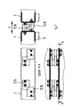
- the pull-out device (11) consists of four individually movable according to Figures 4 and 5 Cam grippers (13, 14) which are endless over four revolving roller chains (19), individually via servo motors are driven.
- the two outer grippers (13) and the two inner grippers (14) each work in pull-out mode, mutually and in pairs.
- On inner (14) and an outer (13) gripper form together a gripper set.
- stop strips (15) are attached where the cam grippers (13, 14) can jam.
- the two outer cam grippers (13) reach under the Roll pallets (3) on the stop bars (15), the two inner cam gripper (14) grip the cam gripper from the other side of the stop bars (15).
- the cam grippers (13, 14) then move the Rolling pallets (3) in the Z direction via the chain movement by means of a servo chain drive. Since the cam grippers (13, 14) on the transfer carriage (1) and the elevators (2) as well as the stop bars (15) on the roller pallets are conical, arise after clamping upwards a positive connection, so that also empty roller pallets (3) do not come out of the pull-out device can jump.
- the drawers can be optimally controlled.
- the cam grippers (13, 14) can be adjusted individually for conveying through, see above that the roller pallets (3) are always at least two Cam grippers (13, 14) are held. So that the roller chains no tilting moments when pulling out receive. are the gripper cams (13, 14) via guide rollers (17) a linear guide in rail guides (18) guided linearly.
- the shift length of the Pull-out device (11) is built so long that the foremost Roll pallets (3) left and right in the storage channels (6) can be driven under and thus without Transverse shift of the transfer carriage lower table (1) get along in the Z direction.
- the pull-out devices (11) on the elevators (2) must be in vertical travel the roller pallets (3) laterally in the storage channels (6) or the transfer points (5) can cross. she The roller pallets (3) on the side must not be driven under. For these pull-out devices (11) an additional, Lower table movable in Z direction required.
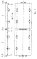
- Figures 6 and 7 show the coupling device (12) with symmetrical spacing from the center line Coupling elements that pull symmetrically of the rolling pallets (3).
- To a bumpless To enable rail interrupters to be run over is also the arrangement of two or more Roller pairs per axis (see Figures 6 and 7) intended.
Landscapes
- Engineering & Computer Science (AREA)
- Mechanical Engineering (AREA)
- Warehouses Or Storage Devices (AREA)
- Stacking Of Articles And Auxiliary Devices (AREA)
Description
- Figur 1
- eine Übersicht eines Kompaktlagers mit der Anwendung der Auszugsvorrichtung (11) und der Koppelvorrichtung (12),
- Figur 2
- zwei Rollpaletten (3) mit der Koppelvorrichtung (12) auf der Mittellinie,
- Figur 3
- eine Koppelvorrichtung (12) nach Figur 2 im Detail
- Figur 4
- eine schematische Darstellung eines Auszuges mit gleichzeitigem Lagerkanalwechsel der Rollpalette (3) von links nach rechts,
- Figur 5
- eine Auszugsvorrichtung (11) im Detail,
- Figur 6
- zwei Rollpaletten (3) mit zweiteiliger Koppelvorrichtung (12) symmetrisch im Abstand zur Mittellinie,
- Figur 7
- eine Koppelvorrichtung (12) nach Figur 6 im Detail
Claims (9)
- Verfahren zum Ausziehen und Koppeln von Rollpaletten (3) in der Kompakt-Lagertechnik mittels einer Auszugsvorrichtung (11) für einen Verschiebewagen (1) bzw. Aufzug (2) sowie mittels Rollpaletten (3), die Koppelvorrichtungen aufweisen, mit einer Auszugsvorrichtung, die einzeln antreibbare, umlaufende Rollenketten (19) mit daran befestigten Nockengreifern (13, 14) aufweist, wobei diese Nockengreifer mit an zwei Seiten der Rollpalette (3) angeordneten Anschlagleisten (15) in eine spielfrei gehaltene Klemmposition gebracht werden können, um die Rollpalette auf einen Verschiebewagen bzw. Aufzug zu ziehen, der die Rollpalette weiterbefördert,
dadurch gekennzeichnet, daß die Bewegungsrichtungen beim Ausziehen und Koppeln der Rollpaletten (3) in einem 3-dimensionalen Koordinatensystem mit X-, Y- und Z-Achse festgelegt sind, die wobei auf den Verschiebewagen (1) das Koppeln durch die Bewegungskombination in der Z-und X-Achse und auf den Aufzügen (2) durch die Bewegungskombination in der Z- und Y-Achse erfolgt, und wobei die Auszugsvorrichtung (11) die Rollpalette (3) an den Anschlagleisten (15) über einen oder mehrere angetriebene Nockengreifer (13, 14) in Z-Richtung herauszieht, während ein oder mehrere angetriebene Nockengreifer (13, 14) auf der in Z-Richtung gegenüberliegenden Seite der Anschlagleisten (15) dagegen halten und so die Rollpalette (3) in X-Richtung mit einer über eine Steuerung und Drehmomentregelung erzeugte definierte Klemmkraft absolut spielfrei halten,
daß die Auszugsvorrichtung aus vier endlos umlaufenden Rollenketten (19), auf denen jeweils ein Nockengreifer (13, 14) angeordnet ist, besteht, die einzeln angetrieben werden,
daß jeweils zwei Rollenketten(19) einen Greifersatz mit gegensinnig bewegbaren Nokkengreifern (13, 14) bilden,
und daß während der Position der Rollpalette (3) auf dem Verschiebewagen (1) bzw. Aufzug (2) jeweils nur ein Greifersatz derart gesteuert wird, daß der einzelne Greifersatz bei einem bevorstehenden Wechsel der Rollpalette auf die entgegengesetzte Seite der Lagerposition an der gegenüberliegenden Anschlagleiste (15) der Rollpalette (3) spielfrei klemmend in Eingriff gebracht wird, wobei der andere Greifersatz während dieses Umgreifvorganges seinen spielfreien Klemmgriff an der anderen Anschlagleiste (15) beibehält. - Auszugsvorrichtung zur Durchführung eines Verfahrens zum Ausziehen und Koppeln von Rollpaletten (3), die Koppelvorrichtungen (12) und Anschlagleisten (15) aufweisen, nach Anspruch 1, wobei die Auszugsvorrichtung einzeln antreibbare, umlaufende Rollenketten (19) mit daran befestigten Nockengreifern (13, 14) aufweist und wobei diese Nockengreifer an einer an der Rollpalette (3) angeordneten Anschlagleiste (15) in eine spielfrei gehaltene Klemmposition gebracht werden können, um die Rollpalette auf einen Verschiebewagen (1) bzw. Aufzug (2) zu ziehen, der die Rollpalette weiterbefördert,
dadurch gekennzeichnet, daß die Auszugsvorrichtung (11) vier endlos umlaufende und mittels Servomotoren separat antreibbare Rollenketten (19) aufweist, wobei auf jeder Rollenkette jeweils ein Nokkengreifer (13, 14) angeordnet ist,
daß die Nockengreifer mit der Anschlagleiste eine formschlüssige Verbindung bilden können,
daß jeweils zwei nebeneinanderliegende Rollenketten (19) mit ihren gegensinnig bewegbaren Nockengreifern (13, 14) einen Greifersatz bilden,
daß die Greifersätze gemeinsam und/oder unabhängig voneinander steuerbar ausgebildet sind, derart, daß beim Auszugsvorgang der Rollpalette (3) auf den Verschiebewagen (1) bzw. Aufzug (2) beide Greifersätze gemeinsam an einer Anschlagleiste (15) der Rollpalette spielfrei klemmend angreifen und daß beim Umgreifvorgang vor einem Wechsel der Rollpalette auf die andere Seite der Lagerposition ein einzelner Greifersatz zur gegenüberliegenden Anschlagleiste (15) bewegbar und mit dieser in einen spielfreien Klemmgriff bringbar ist, wobei ein Nockengreifer die Rollpalette in Z-Richtung zieht und ein zweiter Nockengreifer auf der in Z-Richtung gegenüberliegenden Seite der Anschlagleiste dagegen hält. - Auszugsvorrichtung nach Anspruch 2
dadurch gekennzeichnet, daß die Auszugsvorrichtung (11) mit den Anschlagleisten (15) an der Rollpalette (3) sowie den Nockengreifern (13, 14) am Verschiebewagen (1) oder Aufzug (2) durch die konstruktive Formgebung nach oben zwischen Nockengreifer (13, 14) und Anschlagleiste (15) durch eine konische Ausbildung der Anschlagleisten (15) und der Nockengreifer (13, 14) eine formschlüssige Verbindung bilden können - Auszugsvorrichtung nach Anspruch 2 oder 3,
dadurch gekennzeichnet, daß die Auszugsvorrichtung (11) über Rollenketten endlos umlaufend angetrieben, im Auszugs- und Klemmbereich der Rollpalette (3) derart geführt ist, daß das Kippmoment, entstehend aus Auszugskraft und Klemmkraft der Nockengreifer (13, 14) über die Linearführungen (17, 18) aufgenommen wird. - Rollpalette mit Koppelvorrichtungen (12) und Anschlagleisten (15) zur Durchführung eines Verfahrens nach Anspruch 1 mittels einer Vorrichtung nach Anspruch 2, dadurch gekennzeichnet, daß die Rollpalette (3) auf ihrer Unterseite mit Anschlagleisten (15) ausgebildet ist, welche mit zwei oder mehreren der angetriebenen Nockengreifer (13, 14) der Auszugsvorrichtung (11) eine formschlüssige Verbindung bilden können und daß die Koppelvorrichtung (12) an der Rollpalette (3) aus mehreren in Z-Richtung verschraubten und getrennten Einzelpaletten (16) aus verschiedenen Materialien verschiedener Härte hergestellt ist.
- Rollpalette nach Anspruch 5,
dadurch gekennzeichnet, daß die Platten (16) der Koppelvorrichtung (12) derart in Z-Richtung angeordnet sind,
daß die Koppelvorrichtungen (12) in vertikaler Fahrt auf dem im Kompaktlager in Y-Richtung verfahrbar angeordneten Aufzug (2) von unten und von oben direkt eingekoppelt durchfahren werden kann und in horizontaler Fahrt innerhalb der horizontal ausgerichteten Fahrbahn ebenen (4) des Kompaktlagers in X-Richtung auf dem Verschiebewagen (1) von beiden Seiten in X-Richtung direkt eingekoppelt durchfahren werden kann. - Rollpalette nach Anspruch 6,
dadurch gekennzeichnet, daß die Koppelvorrichtung (12) auf der Mittellinie der Rollpalette (3) in Z-Richtung angeordnet ist - Rollpalette nach Anspruch 6,
dadurch gekennzeichnet, daß die Koppelvorrichtung (12) aus zwei Koppelelementen besteht, die symmetrisch in gleichem Abstand zur Mittellinie der Rollpalette (3) in Z-Richtung angeordnet sind. - Rollpalette nach einem oder mehreren der Ansprüche 6 bis 8,
dadurch gekennzeichnet, daß pro Radachse zwei oder mehrere Rollenpaare angeordnet sind.
Applications Claiming Priority (4)
| Application Number | Priority Date | Filing Date | Title |
|---|---|---|---|
| CH3032/95 | 1995-10-27 | ||
| CH303295 | 1995-10-27 | ||
| CH303295 | 1995-10-27 | ||
| PCT/EP1996/004612 WO1997015513A1 (de) | 1995-10-27 | 1996-10-24 | Vorrichtung zum ausziehen von rollpaletten in der kompakt-lagertechnik, sowie rollpalette hierfür |
Publications (3)
| Publication Number | Publication Date |
|---|---|
| EP0857152A1 EP0857152A1 (de) | 1998-08-12 |
| EP0857152B1 EP0857152B1 (de) | 1999-06-16 |
| EP0857152B2 true EP0857152B2 (de) | 2004-03-17 |
Family
ID=4247100
Family Applications (1)
| Application Number | Title | Priority Date | Filing Date |
|---|---|---|---|
| EP96938031A Expired - Lifetime EP0857152B2 (de) | 1995-10-27 | 1996-10-24 | Verfahren und vorrichtung zum ausziehen von rollpaletten in der kompakt-lagertechnik, sowie rollpalette hierfür |
Country Status (5)
| Country | Link |
|---|---|
| EP (1) | EP0857152B2 (de) |
| AT (1) | ATE181302T1 (de) |
| DE (1) | DE59602266D1 (de) |
| ES (1) | ES2137021T5 (de) |
| WO (1) | WO1997015513A1 (de) |
Families Citing this family (9)
| Publication number | Priority date | Publication date | Assignee | Title |
|---|---|---|---|---|
| ATE227683T1 (de) * | 1997-08-22 | 2002-11-15 | Swisslog Logistiksysteme Gmbh | Dynamisches kompaktlager |
| DE10105706A1 (de) * | 2001-02-08 | 2002-09-05 | Siemens Production & Logistics | Regallager |
| DE102014101005B4 (de) * | 2014-01-28 | 2021-02-18 | SSI Schäfer AG | Mitnehmereinheit für ein Zugmittel, Antriebskette mit einer Mitnehmereinheit sowie Lagersystem mit zumindest einem Kettentrieb |
| DE102015101416A1 (de) * | 2015-01-30 | 2016-08-04 | Hubtex Maschinenbau Gmbh & Co. Kg | Flurförderer und System mit einem Flurförderer |
| US11724876B2 (en) | 2016-05-24 | 2023-08-15 | RoBotany Ltd. | Apparatus and method for autonomous agriculture inventory management |
| NO346327B1 (en) * | 2017-05-16 | 2022-06-07 | Autostore Tech As | Automated storage and retrieval system |
| NO344463B1 (en) * | 2017-05-16 | 2019-12-23 | Autostore Tech As | Automated storage and retrieval system and method of operating same |
| JP7049369B2 (ja) | 2017-05-16 | 2022-04-06 | オートストアー テクノロジー アーエス | 自動化貯蔵および回収システム |
| EP3887289A4 (de) * | 2018-11-30 | 2022-09-28 | Robotany Ltd. | Vorrichtung und verfahren zur autonomen bestandsverwaltung in der landwirtschaft |
Citations (3)
| Publication number | Priority date | Publication date | Assignee | Title |
|---|---|---|---|---|
| EP0126431B1 (de) † | 1983-05-18 | 1986-09-10 | Gerhard Pantzer | Durchschub-/Einschublager für Rollpaletten, Gitterboxen und dergl. |
| DE3805712A1 (de) † | 1988-02-24 | 1989-09-07 | Pantzer Gerhard | Positioniervorrichtung fuer rollwagen eines rollwagenlagers |
| EP0500065B1 (de) † | 1991-02-21 | 1996-11-27 | MIELE & CIE. GMBH & CO. | Lager für auf Paletten transportierbares Lagergut |
Family Cites Families (5)
| Publication number | Priority date | Publication date | Assignee | Title |
|---|---|---|---|---|
| FR1443101A (fr) * | 1965-01-22 | 1966-06-24 | Ct D Etudes Et D Applic Des Te | Procédé et installation d'emmagasinage et de manutention en magasin |
| JPS6198708U (de) * | 1984-12-03 | 1986-06-24 | ||
| DE3624033A1 (de) * | 1986-02-03 | 1987-08-06 | Kessler Friedrich & Co | Transport- und wechselvorrichtung mit einem endlos umlaufenden kettentrieb |
| GB8807659D0 (en) * | 1988-03-31 | 1988-05-05 | Kliklok International Ltd | Conveyors |
| DE4233690C2 (de) * | 1992-10-02 | 1995-03-09 | Bellheimer Metallwerk Gmbh | Vorrichtung zum Ein- und Auslagern von Lastträgern in ein Regal bzw. aus einem Regal |
-
1996
- 1996-10-24 DE DE59602266T patent/DE59602266D1/de not_active Expired - Fee Related
- 1996-10-24 WO PCT/EP1996/004612 patent/WO1997015513A1/de not_active Ceased
- 1996-10-24 EP EP96938031A patent/EP0857152B2/de not_active Expired - Lifetime
- 1996-10-24 AT AT96938031T patent/ATE181302T1/de not_active IP Right Cessation
- 1996-10-24 ES ES96938031T patent/ES2137021T5/es not_active Expired - Lifetime
Patent Citations (3)
| Publication number | Priority date | Publication date | Assignee | Title |
|---|---|---|---|---|
| EP0126431B1 (de) † | 1983-05-18 | 1986-09-10 | Gerhard Pantzer | Durchschub-/Einschublager für Rollpaletten, Gitterboxen und dergl. |
| DE3805712A1 (de) † | 1988-02-24 | 1989-09-07 | Pantzer Gerhard | Positioniervorrichtung fuer rollwagen eines rollwagenlagers |
| EP0500065B1 (de) † | 1991-02-21 | 1996-11-27 | MIELE & CIE. GMBH & CO. | Lager für auf Paletten transportierbares Lagergut |
Also Published As
| Publication number | Publication date |
|---|---|
| EP0857152B1 (de) | 1999-06-16 |
| ES2137021T5 (es) | 2004-10-01 |
| ES2137021T3 (es) | 1999-12-01 |
| ATE181302T1 (de) | 1999-07-15 |
| DE59602266D1 (de) | 1999-07-22 |
| EP0857152A1 (de) | 1998-08-12 |
| WO1997015513A1 (de) | 1997-05-01 |
Similar Documents
| Publication | Publication Date | Title |
|---|---|---|
| DE102007059611B4 (de) | Verfahren und Vorrichtung zum Transportieren von Objekten | |
| EP1638866B1 (de) | Verfahren und vorrichtung zur manipulation von ladehilfsmitteln | |
| DE3784980T2 (de) | Kurzhubtransferpresse mit automatischer vorschubeinrichtung. | |
| EP1401743A2 (de) | Transportwagen zum ein- und auslagern von transportgut | |
| EP0773077B1 (de) | Presse mit kombinierter Transfereinrichtung | |
| DE3443076A1 (de) | Flexibles fertigungssystem fuer die bearbeitung und herstellung mehrteiliger baugruppen, insbesondere rohkarosserie-baugruppen | |
| DE2825213A1 (de) | Vorrichtung und verfahren zur handhabung von gegenstaenden | |
| EP0671228B1 (de) | Transporteinrichtung für Werkstücke in einer Presse | |
| EP2433882A1 (de) | Verfahren zum Einlagern von Waren sowie Vorrichtung dazu | |
| EP2484483B1 (de) | Zuführ- und Ladeeinheit | |
| EP1468948A1 (de) | Zuschneideanlage mit zwei gegeneinander verfahrbaren Greiferbalken | |
| EP0582093B1 (de) | Platinenzuführeinrichtung für eine Presse | |
| EP0665722B1 (de) | Verfahren und anordnung zum fördern flächiger werkstücke | |
| EP0741662B1 (de) | Regalbediengerät | |
| EP0857152B2 (de) | Verfahren und vorrichtung zum ausziehen von rollpaletten in der kompakt-lagertechnik, sowie rollpalette hierfür | |
| EP4363352B1 (de) | Verfahren zum einlagern oder auslagern von lagerhilfsmitteln | |
| DE10122657A1 (de) | Zugeinheit für eine Ziehmaschine und Verfahren zum Ziehen eines Ziehgutes mit dieser Zugeinheit | |
| DE202008010202U1 (de) | Transporteinrichtung | |
| DE3826875C2 (de) | ||
| EP0621093A1 (de) | Transporteinrichtung zum Transportieren von Werkstücken in einer Pressenstrasse, einer Grossteil-Stufenpresse oder dergleichen | |
| DE69621886T2 (de) | Vorrichtung und verfahren zum herstellen von werkstücken | |
| DE4325446C2 (de) | Regalbediengerät mit Gegengewichtsanordnung und einem einzigen Antriebsmittel für Hub- und Senkbewegung | |
| EP0507098B1 (de) | Transporteinrichtung zum Transportieren von grossflächigen Teilen in einer Stufenpresse | |
| DE69621443T2 (de) | Verbesserte spannrahmen-wechselvorrichtung | |
| AT500227B1 (de) | Transportwagen zum ein- und auslagern von transportgut |
Legal Events
| Date | Code | Title | Description |
|---|---|---|---|
| PUAI | Public reference made under article 153(3) epc to a published international application that has entered the european phase |
Free format text: ORIGINAL CODE: 0009012 |
|
| 17P | Request for examination filed |
Effective date: 19980424 |
|
| AK | Designated contracting states |
Kind code of ref document: A1 Designated state(s): AT BE CH DE DK ES FI FR GB IT LI NL PT SE |
|
| GRAG | Despatch of communication of intention to grant |
Free format text: ORIGINAL CODE: EPIDOS AGRA |
|
| GRAG | Despatch of communication of intention to grant |
Free format text: ORIGINAL CODE: EPIDOS AGRA |
|
| GRAH | Despatch of communication of intention to grant a patent |
Free format text: ORIGINAL CODE: EPIDOS IGRA |
|
| 17Q | First examination report despatched |
Effective date: 19981127 |
|
| GRAH | Despatch of communication of intention to grant a patent |
Free format text: ORIGINAL CODE: EPIDOS IGRA |
|
| GRAA | (expected) grant |
Free format text: ORIGINAL CODE: 0009210 |
|
| AK | Designated contracting states |
Kind code of ref document: B1 Designated state(s): AT BE CH DE DK ES FI FR GB IT LI NL PT SE |
|
| PG25 | Lapsed in a contracting state [announced via postgrant information from national office to epo] |
Ref country code: SE Free format text: THE PATENT HAS BEEN ANNULLED BY A DECISION OF A NATIONAL AUTHORITY Effective date: 19990616 Ref country code: FR Free format text: LAPSE BECAUSE OF NON-PAYMENT OF DUE FEES Effective date: 19990616 Ref country code: FI Free format text: LAPSE BECAUSE OF NON-PAYMENT OF DUE FEES Effective date: 19990616 |
|
| REF | Corresponds to: |
Ref document number: 181302 Country of ref document: AT Date of ref document: 19990715 Kind code of ref document: T |
|
| REG | Reference to a national code |
Ref country code: CH Ref legal event code: EP |
|
| REF | Corresponds to: |
Ref document number: 59602266 Country of ref document: DE Date of ref document: 19990722 |
|
| ITF | It: translation for a ep patent filed | ||
| PG25 | Lapsed in a contracting state [announced via postgrant information from national office to epo] |
Ref country code: DK Free format text: LAPSE BECAUSE OF FAILURE TO SUBMIT A TRANSLATION OF THE DESCRIPTION OR TO PAY THE FEE WITHIN THE PRESCRIBED TIME-LIMIT Effective date: 19990916 |
|
| REG | Reference to a national code |
Ref country code: CH Ref legal event code: NV Representative=s name: PA ALDO ROEMPLER |
|
| ET | Fr: translation filed | ||
| GBT | Gb: translation of ep patent filed (gb section 77(6)(a)/1977) |
Effective date: 19990916 |
|
| REG | Reference to a national code |
Ref country code: PT Ref legal event code: SC4A Free format text: AVAILABILITY OF NATIONAL TRANSLATION Effective date: 19990818 |
|
| REG | Reference to a national code |
Ref country code: ES Ref legal event code: FG2A Ref document number: 2137021 Country of ref document: ES Kind code of ref document: T3 |
|
| PLAV | Examination of admissibility of opposition |
Free format text: ORIGINAL CODE: EPIDOS OPEX |
|
| PLBI | Opposition filed |
Free format text: ORIGINAL CODE: 0009260 |
|
| PLBF | Reply of patent proprietor to notice(s) of opposition |
Free format text: ORIGINAL CODE: EPIDOS OBSO |
|
| 26 | Opposition filed |
Opponent name: SIEMENS AG ZENTRALABTEILUNG TECHNIK ABTLG. ZT PA 1 Effective date: 20000315 |
|
| NLR1 | Nl: opposition has been filed with the epo |
Opponent name: SIEMENS AG ZENTRALABTEILUNG TECHNIK ABTLG. ZT PA 1 |
|
| PLBF | Reply of patent proprietor to notice(s) of opposition |
Free format text: ORIGINAL CODE: EPIDOS OBSO |
|
| PGFP | Annual fee paid to national office [announced via postgrant information from national office to epo] |
Ref country code: FR Payment date: 20000918 Year of fee payment: 5 |
|
| PGFP | Annual fee paid to national office [announced via postgrant information from national office to epo] |
Ref country code: GB Payment date: 20000922 Year of fee payment: 5 |
|
| PGFP | Annual fee paid to national office [announced via postgrant information from national office to epo] |
Ref country code: PT Payment date: 20001013 Year of fee payment: 5 |
|
| PGFP | Annual fee paid to national office [announced via postgrant information from national office to epo] |
Ref country code: BE Payment date: 20001023 Year of fee payment: 5 |
|
| PG25 | Lapsed in a contracting state [announced via postgrant information from national office to epo] |
Ref country code: GB Free format text: LAPSE BECAUSE OF NON-PAYMENT OF DUE FEES Effective date: 20011024 |
|
| PG25 | Lapsed in a contracting state [announced via postgrant information from national office to epo] |
Ref country code: BE Free format text: LAPSE BECAUSE OF NON-PAYMENT OF DUE FEES Effective date: 20011031 |
|
| RAP2 | Party data changed (patent owner data changed or rights of a patent transferred) |
Owner name: WESTFALIA WST SYSTEMTECHNIK GMBH & CO. KG |
|
| REG | Reference to a national code |
Ref country code: GB Ref legal event code: IF02 |
|
| NLT2 | Nl: modifications (of names), taken from the european patent patent bulletin |
Owner name: WESTFALIA WST SYSTEMTECHNIK GMBH & CO. KG |
|
| BERE | Be: lapsed |
Owner name: KRUPS KOMPAKTLOGISTIK G.M.B.H. Effective date: 20011031 |
|
| PG25 | Lapsed in a contracting state [announced via postgrant information from national office to epo] |
Ref country code: PT Free format text: LAPSE BECAUSE OF NON-PAYMENT OF DUE FEES Effective date: 20020430 |
|
| GBPC | Gb: european patent ceased through non-payment of renewal fee |
Effective date: 20011024 |
|
| REG | Reference to a national code |
Ref country code: FR Ref legal event code: ST |
|
| REG | Reference to a national code |
Ref country code: PT Ref legal event code: MM4A Free format text: LAPSE DUE TO NON-PAYMENT OF FEES Effective date: 20020430 |
|
| RTI2 | Title (correction) |
Free format text: METHOD AND DEVICE FOR EXTRACTING ROLLING PALLETS IN COMPACT STORAGE TECHNOLOGY, AND ROLLING PALLET THEREFOR |
|
| RTI2 | Title (correction) |
Free format text: METHOD AND DEVICE FOR EXTRACTING ROLLING PALLETS IN COMPACT STORAGE TECHNOLOGY, AND ROLLING PALLET THEREFOR |
|
| PUAH | Patent maintained in amended form |
Free format text: ORIGINAL CODE: 0009272 |
|
| STAA | Information on the status of an ep patent application or granted ep patent |
Free format text: STATUS: PATENT MAINTAINED AS AMENDED |
|
| 27A | Patent maintained in amended form |
Effective date: 20040317 |
|
| AK | Designated contracting states |
Kind code of ref document: B2 Designated state(s): AT BE CH DE DK ES FI FR GB IT LI NL PT SE |
|
| REG | Reference to a national code |
Ref country code: CH Ref legal event code: AEN Free format text: AUFRECHTERHALTUNG DES PATENTES IN GEAENDERTER FORM |
|
| NLR2 | Nl: decision of opposition |
Effective date: 20040317 |
|
| NLR3 | Nl: receipt of modified translations in the netherlands language after an opposition procedure | ||
| REG | Reference to a national code |
Ref country code: ES Ref legal event code: DC2A Date of ref document: 20040423 Kind code of ref document: T5 |
|
| EN | Fr: translation not filed | ||
| PGFP | Annual fee paid to national office [announced via postgrant information from national office to epo] |
Ref country code: NL Payment date: 20051003 Year of fee payment: 10 |
|
| PGFP | Annual fee paid to national office [announced via postgrant information from national office to epo] |
Ref country code: AT Payment date: 20051012 Year of fee payment: 10 |
|
| PGFP | Annual fee paid to national office [announced via postgrant information from national office to epo] |
Ref country code: CH Payment date: 20051027 Year of fee payment: 10 |
|
| PGFP | Annual fee paid to national office [announced via postgrant information from national office to epo] |
Ref country code: DE Payment date: 20051028 Year of fee payment: 10 |
|
| PGFP | Annual fee paid to national office [announced via postgrant information from national office to epo] |
Ref country code: ES Payment date: 20051129 Year of fee payment: 10 |
|
| PG25 | Lapsed in a contracting state [announced via postgrant information from national office to epo] |
Ref country code: AT Free format text: LAPSE BECAUSE OF NON-PAYMENT OF DUE FEES Effective date: 20061024 |
|
| PG25 | Lapsed in a contracting state [announced via postgrant information from national office to epo] |
Ref country code: LI Free format text: LAPSE BECAUSE OF NON-PAYMENT OF DUE FEES Effective date: 20061031 Ref country code: CH Free format text: LAPSE BECAUSE OF NON-PAYMENT OF DUE FEES Effective date: 20061031 |
|
| PGFP | Annual fee paid to national office [announced via postgrant information from national office to epo] |
Ref country code: IT Payment date: 20061031 Year of fee payment: 11 |
|
| PG25 | Lapsed in a contracting state [announced via postgrant information from national office to epo] |
Ref country code: NL Free format text: LAPSE BECAUSE OF NON-PAYMENT OF DUE FEES Effective date: 20070501 Ref country code: DE Free format text: LAPSE BECAUSE OF NON-PAYMENT OF DUE FEES Effective date: 20070501 |
|
| REG | Reference to a national code |
Ref country code: CH Ref legal event code: PL |
|
| NLV4 | Nl: lapsed or anulled due to non-payment of the annual fee |
Effective date: 20070501 |
|
| REG | Reference to a national code |
Ref country code: ES Ref legal event code: FD2A Effective date: 20061025 |
|
| PG25 | Lapsed in a contracting state [announced via postgrant information from national office to epo] |
Ref country code: ES Free format text: LAPSE BECAUSE OF NON-PAYMENT OF DUE FEES Effective date: 20061025 |
|
| PLAB | Opposition data, opponent's data or that of the opponent's representative modified |
Free format text: ORIGINAL CODE: 0009299OPPO |
|
| PG25 | Lapsed in a contracting state [announced via postgrant information from national office to epo] |
Ref country code: IT Free format text: LAPSE BECAUSE OF NON-PAYMENT OF DUE FEES Effective date: 20071024 |