EP0857295B1 - Automatisiertes immunotest-verarbeitungssystem - Google Patents
Automatisiertes immunotest-verarbeitungssystem Download PDFInfo
- Publication number
- EP0857295B1 EP0857295B1 EP96937406A EP96937406A EP0857295B1 EP 0857295 B1 EP0857295 B1 EP 0857295B1 EP 96937406 A EP96937406 A EP 96937406A EP 96937406 A EP96937406 A EP 96937406A EP 0857295 B1 EP0857295 B1 EP 0857295B1
- Authority
- EP
- European Patent Office
- Prior art keywords
- fluid
- aspirate
- tip
- head
- processing system
- Prior art date
- Legal status (The legal status is an assumption and is not a legal conclusion. Google has not performed a legal analysis and makes no representation as to the accuracy of the status listed.)
- Expired - Lifetime
Links
Images


Classifications
-
- G—PHYSICS
- G01—MEASURING; TESTING
- G01F—MEASURING VOLUME, VOLUME FLOW, MASS FLOW OR LIQUID LEVEL; METERING BY VOLUME
- G01F23/00—Indicating or measuring liquid level or level of fluent solid material, e.g. indicating in terms of volume or indicating by means of an alarm
- G01F23/22—Indicating or measuring liquid level or level of fluent solid material, e.g. indicating in terms of volume or indicating by means of an alarm by measuring physical variables, other than linear dimensions, pressure or weight, dependent on the level to be measured, e.g. by difference of heat transfer of steam or water
- G01F23/26—Indicating or measuring liquid level or level of fluent solid material, e.g. indicating in terms of volume or indicating by means of an alarm by measuring physical variables, other than linear dimensions, pressure or weight, dependent on the level to be measured, e.g. by difference of heat transfer of steam or water by measuring variations of capacity or inductance of capacitors or inductors arising from the presence of liquid or fluent solid material in the electric or electromagnetic fields
- G01F23/263—Indicating or measuring liquid level or level of fluent solid material, e.g. indicating in terms of volume or indicating by means of an alarm by measuring physical variables, other than linear dimensions, pressure or weight, dependent on the level to be measured, e.g. by difference of heat transfer of steam or water by measuring variations of capacity or inductance of capacitors or inductors arising from the presence of liquid or fluent solid material in the electric or electromagnetic fields by measuring variations in capacitance of capacitors
-
- B—PERFORMING OPERATIONS; TRANSPORTING
- B01—PHYSICAL OR CHEMICAL PROCESSES OR APPARATUS IN GENERAL
- B01L—CHEMICAL OR PHYSICAL LABORATORY APPARATUS FOR GENERAL USE
- B01L13/00—Cleaning or rinsing apparatus
- B01L13/02—Cleaning or rinsing apparatus for receptacle or instruments
-
- G—PHYSICS
- G01—MEASURING; TESTING
- G01F—MEASURING VOLUME, VOLUME FLOW, MASS FLOW OR LIQUID LEVEL; METERING BY VOLUME
- G01F23/00—Indicating or measuring liquid level or level of fluent solid material, e.g. indicating in terms of volume or indicating by means of an alarm
- G01F23/22—Indicating or measuring liquid level or level of fluent solid material, e.g. indicating in terms of volume or indicating by means of an alarm by measuring physical variables, other than linear dimensions, pressure or weight, dependent on the level to be measured, e.g. by difference of heat transfer of steam or water
- G01F23/24—Indicating or measuring liquid level or level of fluent solid material, e.g. indicating in terms of volume or indicating by means of an alarm by measuring physical variables, other than linear dimensions, pressure or weight, dependent on the level to be measured, e.g. by difference of heat transfer of steam or water by measuring variations of resistance of resistors due to contact with conductor fluid
- G01F23/245—Indicating or measuring liquid level or level of fluent solid material, e.g. indicating in terms of volume or indicating by means of an alarm by measuring physical variables, other than linear dimensions, pressure or weight, dependent on the level to be measured, e.g. by difference of heat transfer of steam or water by measuring variations of resistance of resistors due to contact with conductor fluid with a probe moved by an auxiliary power, e.g. meter, to follow automatically the level
-
- B—PERFORMING OPERATIONS; TRANSPORTING
- B01—PHYSICAL OR CHEMICAL PROCESSES OR APPARATUS IN GENERAL
- B01L—CHEMICAL OR PHYSICAL LABORATORY APPARATUS FOR GENERAL USE
- B01L3/00—Containers or dishes for laboratory use, e.g. laboratory glassware; Droppers
- B01L3/50—Containers for the purpose of retaining a material to be analysed, e.g. test tubes
- B01L3/508—Rigid containers without fluid transport within
- B01L3/5082—Test tubes per se
-
- G—PHYSICS
- G01—MEASURING; TESTING
- G01N—INVESTIGATING OR ANALYSING MATERIALS BY DETERMINING THEIR CHEMICAL OR PHYSICAL PROPERTIES
- G01N35/00—Automatic analysis not limited to methods or materials provided for in any single one of groups G01N1/00 - G01N33/00; Handling materials therefor
- G01N35/10—Devices for transferring samples or any liquids to, in, or from, the analysis apparatus, e.g. suction devices, injection devices
- G01N35/1009—Characterised by arrangements for controlling the aspiration or dispense of liquids
- G01N2035/1025—Fluid level sensing
-
- G—PHYSICS
- G01—MEASURING; TESTING
- G01N—INVESTIGATING OR ANALYSING MATERIALS BY DETERMINING THEIR CHEMICAL OR PHYSICAL PROPERTIES
- G01N35/00—Automatic analysis not limited to methods or materials provided for in any single one of groups G01N1/00 - G01N33/00; Handling materials therefor
- G01N35/10—Devices for transferring samples or any liquids to, in, or from, the analysis apparatus, e.g. suction devices, injection devices
- G01N35/1065—Multiple transfer devices
Definitions
- the present invention relates to an automated immunoassay processing system.
- these products may be dispensed into cells in reaction trays to enable analysis of the various products to be performed. After a reagent or a plurality of reagents have been dispensed into the cells in the reaction tray, the reagents are then left for a period of time to allow incubation of a biological process or for a chemical reaction or the like to occur.
- the reagent is aspirated from the cell. It may also be desirable to check that all of the reagent has been removed from the cells before commencing a washing cycle. During the washing cycle it is also desirable to be able to detect whether the correct amount of washing or cleaning fluid has been dispensed into the cells of the reaction trays and to determine whether all the washing fluid has been removed at the end of the washing cycle.
- Conventionally apparatus used to clean the cells of a reaction tray for example after an incubation period, consists of a washer head with a dispensing tip and an aspirate tip corresponding to each cell.
- GB-2216260 discloses a device for injecting a fixed quantity of liquid into a reaction tray wherein conductive electrodes are positioned on an injection nozzle and a detecting unit cooperates with the electrodes to detect the surface level of a sample liquid.
- US-4451433 discloses an automatic chemical reaction analyzer wherein samples are sequentially dispensed into a reaction tray via a first pipetting tube. Reagent solutions are supplied to the reaction trays via a second, conductive, pipetting tube. The liquid levels of the solutions in the reaction trays are detected by a liquid level sensor formed by the second pipetting tube and a conductive electrode.
- the object of the present invention is to provide a new and improved automated immunoassay processing system.
- An automated immunoassay processing system including a level sensor, comprising:
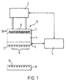
- Figure 1 shows a washer head 13 mounted to be driven vertically up and down by a drive means 2 such as a stepper motor.
- the drive means 2 is controlled by a control means 1 which may include a program-controlled processor.
- a matrix of 8 x 3 dispense and aspirate tips 6 are positioned on the washer head 13.
- the washer head 13 further comprises a printed circuit board (PCB) 5 attached to an insulating block 4.
- PCB printed circuit board
- An exit passage 10 is provided to allow the removal of fluid drawn along an aspirate fluid path, which includes aspirate tips 6.
- the aspirate tips 6 are divided into top and bottom sections 6a and 6b as shown in Figure 2.
- Each top section 6a consists of an upper electrode section inserted into a counterbore within the upper surface of the insulating block 4 and each bottom section 6b consists of a lower electrode section inserted into a corresponding counterbore within the lower surface of the insulating block 4.
- the upper and lower electrode sections consist preferably of stainless steel fabricated in the form of a tube.
- the external diameter of the counterbores is larger than the central bore 11.
- the external diameter of the counterbores may be 1.4 mm whereas the central bore 11 is preferably 1.0 mm.
- the internal diameter of the upper and lower sections of the aspirate tips 6 which are inserted into the two counterbores are typically substantially the same diameter as the internal diameter of the central communicating bore 11.
- the central communicating bore 11 defines at least a portion of the aspirate fluid path.
- the depth of the counterbore in the upper surface of the insulating block 4 is typically 20 mm and the depth of the counterbore in the lower surface of the insulating block 4 is typically 30 mm.
- a reaction tray 8 is vertically spaced below the washer head 13 and the aspirate tips 6.
- the drive means 2 consists of a stepper motor which can control the vertical displacement of the washer head 13 and aspirate tips 6.
- the stepper motor can control the vertical displacement of the washer head 13 in steps of 0.1 mm.
- the washer head may be lowered at a rate of 75 mms -1 .
- the control means 1 communicates with the PCB 5 of the washer head 13.
- a fluid or level sensor is provided by arranging two conductive electrode sections, electrically insulated from each other, for example by means of an air gap or other means, along an aspirate fluid path.
- the air gap is preferably a few millimetres wide.
- Detector means is connected across the conductive electrode sections to detect the presence of a fluid by detecting a change in conductance between the electrode sections. Since the vertical position of the washer head 13 relative to the reaction tray 8 may be known or determined, for example by the control means 1 and/or the drive means 2, then the sensor may function as a level sensor.
- the upper section 6a of the aspirate tip 6 is held, in use, at substantially zero electrical potential.
- zero potential supply means is provided by a rod or tube 7 inserted through a hole or bore axially disposed through the insulating block 4 and through the PCB 5.
- the top portion of the tube 7 is electrically connected to the top sections of the other aspirate tips 6 in the chamber 9 by means of a connecting means 3.
- the connecting means consists of a metal spring or the like.
- the tube 7 is electrically connected to the PCB by an electrical connection 12, for example conductive glue or resin.
- the lower sections of the aspirate tip 6 also pass through the PCB 5 and are similarly connected to appropriate tracks on the underside of the PCB 5 by means of electrical connections 12.
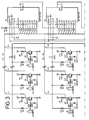
- the electrical connections 12 to the aspirate tips 6 are connected according to the preferred embodiment to connectors J1-24 as shown in the circuit diagram in Figure 3.
- the end of the lower section of the aspirate tip 6 may be chamfered, for example by a laser, to form a more defined tip portion.
- the end of the aspirate tip 6 may also be formed into the shape of a needle.
- the electrical connections and components on the PCB 5 are positioned on the lower surface of the PCB 5.
- a single zero potential supply means 7 is provided per row of aspirate tips 6. Therefore according to the preferred embodiment (a matrix of 3x8 aspirate and dispense tips) three zero potential supply means 7 are provided.
- An electrical circuit thus connected to the upper and lower sections of the aspirate tips 6 measures the conductance between the upper and lower sections of the aspirate tip 6.
- the circuit generates an output indicating the presence of fluid passing between the two sections of the tip 6 by detecting the change in conductance between the two sections of the aspirate tip 6.
- reagents and washing fluids are aqueous based ionic solutions and can be detected according to the present invention.
- Figure 3 is a circuit diagram of part of the detector circuit of a conductive washer head 13.
- twenty four aspirate tips are connected to the PCB 5 by means of electrical connections 12.
- a different number of aspirate tips may be used. For example, 8, 16, 32 or 64 aspirate tips 6 may be used as desired.
- Pin 7 (HS0) and Pin 8 (HS1) of connector J25 are set to determine which model of apparatus (namely the number of aspirate tips) is being used.
- Pin 1 is supplied with + 5V and pin 6 with 0V from the control means 1.
- Pin 2 provides shift out, and pin 3 receives a shift clock.
- Pin 4 receives shift load and pin 5 the oscillator OSC signal.
- the period of the oscillator is set at 1-2 ms. This is significantly slower than that of the clock period, but is set at such a value due to delays in measuring the presence of fluid because of polarisation effects in the aspirate tip 6.
- the clock input pulses have a period of substantially 1 ⁇ s and the load input pulse has substantially a similar period.
- On every load pulse the outputs from each of the fluid sensors are stored in shift registers U1-3.
- the states of the twenty-four fluid sensors of the preferred embodiment are then cleared from the shift registers U1-3 after twenty-four consecutive clock pulses.
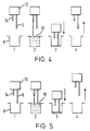
- FIG. 4 shows some of the steps in a normal wash cycle.
- Washer head 13 is provided with pairs of dispense tips 14 and aspirate tips 6.
- the washer head 13 can be moved up and down by means of the mechanical positioning device or drive means 2.
- the drive means 2 is used to position the vertical height of the dispense 14 and aspirate 6 tips as desired during the various stages of a wash cycle.
- a normal wash cycle comprises the steps of firstly positioning the washer head 13 above a sample or container 8, for example a cell of a reaction tray.
- the required volume of wash fluid 15 is then dispensed into the container 8 positioned below the dispense tip 14 as shown in step 2.
- the head 13 and the attached tips 6, 14, are then lowered towards the sample or container 8.
- the aspirate tip 6 is longer in length than the dispense tip 14.
- a suction or aspirate means is activated whilst the washer head 13 is lowered to remove the fluid 15 from the container 8 via the aspirate tip 6.
- the control means 1 can confirm that the liquid level was correct.
- the washer head 13 As the fluid 15 is being removed by the suction or aspirate means the washer head 13 is progressively lowered by drive means 2.
- the level sensor according to the present invention can determine the level of fluid 15 dispensed into the container 8 and also check that when the aspirate tip is lowered all the way to the bottom of the container all of the fluid has been removed. Finally, the washer head 13 and the dispense 14 and aspirate 6 tips are raised clear from the sample or container 8 as shown in step 4 allowing the next step in the processing system to be performed.
- a second type of wash cycle may alternatively or additionally be performed, known as a top wash cycle. This is shown in Figure 5.
- a top wash cycle comprises the steps of firstly positioning the washer head 13 above the container 8 in a similar manner to a normal wash cycle. The washer head 13 is then positioned such that the aspirate tip 6 is set at a level wherein fluid 15 can be aspirated from the container 8 at the same time as fluid 15 is being dispensed from the dispense tip 14 into the container 8. A required quantity of fluid 15 is then dispensed and during this step some of the fluid 15 is aspirated by the aspirate tip 6.
- the washer head 13 When the required sample of fluid 15 has been dispensed the washer head 13 is then lowered by the mechanical positioning means or drive means 2 and the remaining fluid 15 is removed by the aspirate tip 6. Following the removal of any remaining fluid 15 the washer head 13 can be raised clear of the sample 8 (in a similar manner to a normal wash cycle).
- control means 1 can detect the time at which the level sensor detects the presence of fluid 15 flowing along the aspirate path of the aspirate tip 6. The control means 1 can then correlate that the dispense flow rate of fluid from the dispense tip 14 was correct. Towards the end of the third stage of the top or normal wash cycle, the level sensor can determine whether all the fluid 15 has been aspirated from the container 8 before proceeding to the next step wherein the head 13 is raised clear from the sample 8.
- a validation step may preferably be performed before any wash fluid is dispensed.
- the validation step ensures that enough reagent was initially dispensed into the container 8, for example during a sample preparation or incubation stage. This is a separate step to those steps performed during a normal or top wash cycle.
- the validation step comprises positioning the washer head 13 above the container 8 and then lowering the washer head 13 by the mechanical positioning device or drive means 2.
- the aspirate tip 6 aspirates whilst the washer head 13 is being lowered.
- the control means 1 can determine the fluid level and thus whether sufficient reagent or fluid was initially dispensed into the container 8. If the detected fluid level indicates that an insufficient amount of reagent or other fluid was dispensed then an error message may be generated by the control means 1 and the results of that cell can be ignored.
- a validation step may be performed after the wash fluid 15 has been dispensed into the container 8 but before the wash fluid 15 is aspirated out of container 8.
- the validation step checks that the correct amount of wash fluid 15 has been dispensed into the container 8.
- the level sensor is able to determine whether it is necessary for a further amount of wash fluid 15 to be dispensed by the dispense tip 14.
- an error signal may be generated by the control means 1.
- the container or reaction tray 8 may be such as to allow the volume of fluid contained therein to be determined by measuring the height or depth of the fluid.
- a depth of 1 mm corresponds to about 28 ⁇ l.
- the fluid sensor may thus be sensitive to the detection of amounts of about 10 ⁇ l of fluid with 0.1mm steps of the drive means.
- conductance has been used above in its sense of inverse resistance. However, it would be possible to detect variations in impedance more generally, and in particular a change in capacitance between the electrodes, or a change in combined resistance and capacitance. For measuring capacitance it may be preferable to apply an a.c. signal to the electrodes and to insulate the electrodes on their inside surfaces if it is desired to exclude resistive effects through the fluid.
Landscapes
- Physics & Mathematics (AREA)
- Thermal Sciences (AREA)
- Fluid Mechanics (AREA)
- General Physics & Mathematics (AREA)
- Engineering & Computer Science (AREA)
- Power Engineering (AREA)
- Health & Medical Sciences (AREA)
- Clinical Laboratory Science (AREA)
- Chemical & Material Sciences (AREA)
- Chemical Kinetics & Catalysis (AREA)
- Electromagnetism (AREA)
- Automatic Analysis And Handling Materials Therefor (AREA)
Claims (9)
- Automatisiertes Immunassay-Verarbeitungssystem, das einen Niveausensor enthält, mitdadurch gekennzeichnet, daßeinem Kopf (13), der für eine Vertikalbewegung montiert ist, wobei der Kopf (13) eine Ansaugspitze (6) aufweist, die eine innere Durchflußleitung darin aufweist und entlang der ein erstes (6b) und ein zweites (6a) Elektrodenmittel vorgesehen ist, wobei die Elektrodenmittel (6a, 6b) mit einem Detektorstromkreis (5) verbunden sind, der dazu ausgelegt ist, ein Ausgangssignal zu erzeugen, wenn die Elektrodenmittel (6a, 6b) durch Flüssigkeit (15) überbrückt werden,Ansaugmitteln, die mit der Ansaugspitze (6) verbunden sind, einem Motor (2) zum Bewegen des Kopfes,einem Positionierstromkreis zum Steuern des Motors (2), um den Kopf (13) auf bestimmte Vertikalpositionen einzustellen undSteuermitteln (1), die angeschlossen sind, um das Ausgangssignal des Detektorstromkreises (5) zu erhalten,das Ansaugmittel während des Herabsenkens des Kopfes (13) auf die Oberfläche der Flüssigkeit (15) zum Ansaugen ausgelegt ist,das erste (6b) und das zweite (6a) Elektrodenmittel schrittweise so positioniert werden, daß beim Gebrauch Flüssigkeit (15) durch das erste Elektrodenmittel (6b) durchfließt, bevor sie durch das zweite Elektrodenmittel (6a) durchfließt, unddas Steuermittel (1) dazu ausgelegt ist, eine Anzeige des Niveaus oder des Volumens der Flüssigkeit (15) in einer Reaktionszelle (8) durch Bezugnahme auf ein Vertikalpositionssignal zu erzeugen, wenn der Detektorstromkreis ein Ausgabesignal erzeugt, sobald die Ansaugspitze (6) in Kontakt mit Flüssigkeit in der Reaktionszelle (8) tritt, und eine Ausgabe generiert, die die Anwesenheit von Flüssigkeit anzeigt, die während des Ansaugens von Flüssigkeit aus der Reaktionszelle zwischen dem ersten (6b) und dem zweiten (6a) Elektrodenmittel fließt.
- Automatisiertes Immunassay-Verarbeitungssystem nach Anspruch 1, wobei das Steuermittel (1) einen Prozessor aufweist, der dazu ausgelegt ist, Vertikalpositionssignale zur Steuerung des Motors (2) gemäß eines gespeicherten Programms zu erzeugen.
- Automatisiertes Immunassay-Verarbeitungssystem nach Anspruch 1 oder 2, wobei die Elektrodenmittel (6a, 6b) zwei axial beabstandete Metallrohre aufweisen.
- Automatisiertes Immunassay-Verarbeitungssystem nach Anspruch 3, wobei die Metallrohre in einem isolierenden Block (4) montiert sind, der einen Durchgang (11) aufweist, der einen axialen Zentralabschnitt mit geringerem Durchmesser aufweist, der zwei Schultern bereitstellt, an die die Rohre anstoßen.
- Automatisiertes Immunassay-Verarbeitungssystem nach einem der vorstehenden Ansprüche, wobei der Kopf (13) weiter eine Abfüllspitze (14) zum Abfüllen von Waschflüssigkeit in eine Reaktionszelle (8) aufweist.
- Automatisiertes Immunassay-Verarbeitungssystem nach Anspruch 5, wobei die Abfüllspitze (14) dazu ausgelegt ist, Waschflüssigkeit (15) in eine Reaktionszelle (8) abzufüllen, wobei sowohl die Abfüllspitze (14) als auch die Ansaugspitze (6) über der Zelle (8) positioniert sind und wobei, nachdem die Waschflüssigkeit (15) abgefüllt ist, die Ansaugspitze (6) während des Ansaugens abgesenkt wird, das Steuermittel (1) dazu ausgelegt ist, eine Anzeige des Niveaus der Waschflüssigkeit (15) zu erzeugen, wenn die Ansaugspitze (6) die Flüssigkeitsoberfläche erreicht, wodurch die Abfüllung einer richtigen Menge von Waschflüssigkeit (15) bestätigt werden kann.
- Automatisiertes Immunassay-Verarbeitungssystem nach Anspruch 5, wobei die Ansaugspitze (6) dazu ausgelegt ist, innerhalb der Reaktionszelle (8) positioniert zu werden und während des Abfüllens von Waschflüssigkeit (15) aus der Abfüllspitze (14) anzusaugen, das Steuermittel (1) dazu ausgelegt ist, die Zeitperiode zwischen dem Beginn des Abfüllens und der Detektion von Flüssigkeit (15) durch den Detektorstromkreis (5), wenn das Flüssigkeitsniveau die Ansaugspitze (6) erreicht, abzustoppen, und zu bestätigen, daß die Flüssigkeit (15) in einer akzeptablen Geschwindigkeit abgefüllt wird.
- Automatisiertes Immunassay-Verarbeitungssystem nach Anspruch 5, 6 oder 7, wobei vor einem Waschzyklus der Kopf (13) während des Ansaugens abgesenkt wird und das Steuermittel (1) eine Anzeige des Niveaus eines vorher abgefüllten Reagens herstellt, so daß Proben mit nicht genügend Reagens zurückgewiesen werden können.
- Verfahren zum Sensieren bzw. Abfühlen des Flüssigkeitsniveaus in einer Reaktionszelle eines automatisierten Immunassay-Verarbeitungssystems nach Anspruch 1, das die folgenden Schritte aufweist:Absenken des Kopfes (13) zu der Reaktionszelle (8),Ansaugen während des Absenkens des Kopfes (13),Ausgabe eines Signals, wenn die Elektrodenmittel (6a, 6b) durch Flüssigkeit (15) überbrückt werden,Erzeugen einer Anzeige des Niveaus oder des Volumens von Flüssigkeit (15) in der Reaktionszelle (8) durch Bezugnahme auf ein Vertikalpositionssignal, wenn die Ansaugspitze (6) in Kontakt mit Flüssigkeit (15) in der Reaktionszelle (8) tritt, undErzeugen einer Ausgabe, die die Anwesenheit von Flüssigkeit anzeigt, die während des Ansaugens der Flüssigkeit aus der Reaktionszelle zwischen dem ersten (6b) und dem zweiten (6a) Elektrodenmittel fließt,.
Applications Claiming Priority (3)
| Application Number | Priority Date | Filing Date | Title |
|---|---|---|---|
| GB9522056 | 1995-10-27 | ||
| GBGB9522056.2A GB9522056D0 (en) | 1995-10-27 | 1995-10-27 | Level sensor and washer unit |
| PCT/GB1996/002627 WO1997015809A1 (en) | 1995-10-27 | 1996-10-28 | Level sensor and washer unit |
Publications (2)
| Publication Number | Publication Date |
|---|---|
| EP0857295A1 EP0857295A1 (de) | 1998-08-12 |
| EP0857295B1 true EP0857295B1 (de) | 2002-02-06 |
Family
ID=10783004
Family Applications (1)
| Application Number | Title | Priority Date | Filing Date |
|---|---|---|---|
| EP96937406A Expired - Lifetime EP0857295B1 (de) | 1995-10-27 | 1996-10-28 | Automatisiertes immunotest-verarbeitungssystem |
Country Status (6)
| Country | Link |
|---|---|
| US (1) | US6212949B1 (de) |
| EP (1) | EP0857295B1 (de) |
| AU (1) | AU7500896A (de) |
| DE (1) | DE69619120T2 (de) |
| GB (1) | GB9522056D0 (de) |
| WO (1) | WO1997015809A1 (de) |
Families Citing this family (18)
| Publication number | Priority date | Publication date | Assignee | Title |
|---|---|---|---|---|
| ATE446141T1 (de) | 1997-11-14 | 2009-11-15 | Gen Probe Inc | Arbeitsgerät zur analyse |
| US6551557B1 (en) * | 1998-07-07 | 2003-04-22 | Cartesian Technologies, Inc. | Tip design and random access array for microfluidic transfer |
| US6627157B1 (en) * | 1999-03-04 | 2003-09-30 | Ut-Battelle, Llc | Dual manifold system and method for fluid transfer |
| DE19919305A1 (de) * | 1999-04-28 | 2000-11-02 | Roche Diagnostics Gmbh | Verfahren und Vorrichtung zum Flüssigkeitstransfer mit einem Analysegerät |
| AU2005211572B2 (en) * | 2000-02-29 | 2007-06-07 | Gen-Probe Incorporated | Fluid dispense and fluid surface verification system and method |
| CA2724266C (en) | 2000-02-29 | 2012-12-04 | Gen-Probe Incorporated | Fluid dispense and liquid surface verification system and method |
| WO2001068259A1 (en) * | 2000-03-16 | 2001-09-20 | Biogenex Laboratories | Automated specimen processing apparatus with fluid detection |
| US6878554B1 (en) * | 2000-03-20 | 2005-04-12 | Perkinelmer Las, Inc. | Method and apparatus for automatic pin detection in microarray spotting instruments |
| US7282372B2 (en) * | 2002-10-02 | 2007-10-16 | Ortho-Clinical Diagnostics, Inc. | Fluid measurements in a reaction vessel used in conjunction with a clinical analyzer |
| US20060054190A1 (en) * | 2004-09-14 | 2006-03-16 | Bti Holding, Inc. | Plate washing system with ultrasonic cleaning of pipes |
| US8858718B2 (en) * | 2004-09-14 | 2014-10-14 | Bti Holdings, Inc. | Plate washing system with ultrasonic cleaning of pipes and a control method thereof |
| US7432725B2 (en) * | 2006-03-15 | 2008-10-07 | Freescale Semiconductor, Inc. | Electrical field sensors for detecting fluid presence or level |
| US7870797B2 (en) * | 2006-04-03 | 2011-01-18 | Artel, Inc. | Apparatus and method for aspirating and dispensing liquid |
| US7621181B2 (en) * | 2006-04-12 | 2009-11-24 | Siemens Healthcare Diagnostics Inc. | Fluid level detector and analyzer |
| US7777211B2 (en) * | 2007-08-01 | 2010-08-17 | Dynex Technologies, Inc. | Substantially transparent object detection system and method |
| CH704388A2 (de) | 2011-01-27 | 2012-07-31 | Tecan Trading Ag | Einstellverfahren für Mikroplatten-Waschgeräte. |
| UA104658U (uk) * | 2015-08-10 | 2016-02-10 | Микола Артемович Тітаренко | Закупорювальний пристрій, придатний для зливання рідини з пляшки довільними порціями |
| CH712735A1 (de) * | 2016-07-22 | 2018-01-31 | Tecan Trading Ag | Pipettiervorrichtung mit einem Flüssigkeitsvolumensensor und Flüssigkeitsbearbeitungssystem. |
Family Cites Families (14)
| Publication number | Priority date | Publication date | Assignee | Title |
|---|---|---|---|---|
| GB1248084A (en) * | 1969-02-18 | 1971-09-29 | Southern Ind Croydon Ltd | Liquid sensing and indicating device |
| JPS5782769A (en) * | 1980-11-10 | 1982-05-24 | Hitachi Ltd | Automatic analyzing device |
| JPH04279Y2 (de) * | 1981-05-21 | 1992-01-07 | ||
| US4803050A (en) * | 1985-07-22 | 1989-02-07 | Sequoia-Turner Corporation | Method and apparatus for liquid addition and aspiration in automated immunoassay techniques |
| GB8522872D0 (en) * | 1985-09-16 | 1985-10-23 | Flow Lab | Multi-cavity washing apparatus |
| US5045286A (en) * | 1988-02-25 | 1991-09-03 | Olympus Optical Co., Ltd. | Device for aspirating a fixed quantity of liquid |
| GB8824499D0 (en) * | 1988-10-19 | 1988-11-23 | Flow Lab | Automated laboratory equipment |
| US5178834A (en) * | 1989-07-19 | 1993-01-12 | Tosoh Corporation | Automatic immunoassay analyzer |
| FR2654836B1 (fr) * | 1989-11-17 | 1994-01-28 | Biotrol Sa Laboratoires | Appareil d'execution automatique d'un immunodosage en plusieurs etapes successives d'au moins une substance biologique dans une pluralite d'echantillons biologiques, procede et reactif mettant en óoeuvre ledit appareil. |
| ATE154981T1 (de) * | 1990-04-06 | 1997-07-15 | Perkin Elmer Corp | Automatisiertes labor für molekularbiologie |
| JPH0510958A (ja) * | 1991-07-02 | 1993-01-19 | Olympus Optical Co Ltd | 分析装置 |
| AT574U1 (de) * | 1995-02-27 | 1996-01-25 | Slt Labinstruments Gmbh | Vorrichtung zum absaugen einer flüssigkeit aus den kavitäten einer mikrotiterplatte |
| US5897837A (en) * | 1997-02-06 | 1999-04-27 | Toa Medical Electronics Co., Ltd. | Dispensing device and Immunoassay apparatus using the same |
| US5948359A (en) * | 1997-03-21 | 1999-09-07 | Biogenex Laboratories | Automated staining apparatus |
-
1995
- 1995-10-27 GB GBGB9522056.2A patent/GB9522056D0/en active Pending
-
1996
- 1996-10-28 WO PCT/GB1996/002627 patent/WO1997015809A1/en not_active Ceased
- 1996-10-28 AU AU75008/96A patent/AU7500896A/en not_active Abandoned
- 1996-10-28 US US09/065,074 patent/US6212949B1/en not_active Expired - Fee Related
- 1996-10-28 EP EP96937406A patent/EP0857295B1/de not_active Expired - Lifetime
- 1996-10-28 DE DE69619120T patent/DE69619120T2/de not_active Expired - Lifetime
Also Published As
| Publication number | Publication date |
|---|---|
| WO1997015809A1 (en) | 1997-05-01 |
| DE69619120D1 (de) | 2002-03-21 |
| US6212949B1 (en) | 2001-04-10 |
| AU7500896A (en) | 1997-05-15 |
| DE69619120T2 (de) | 2002-08-22 |
| EP0857295A1 (de) | 1998-08-12 |
| GB9522056D0 (en) | 1996-01-03 |
Similar Documents
| Publication | Publication Date | Title |
|---|---|---|
| EP0857295B1 (de) | Automatisiertes immunotest-verarbeitungssystem | |
| US5855851A (en) | Apparatus for trasferring liquid having liquid level sensing function | |
| US4340390A (en) | Method and apparatus for metering biological fluids | |
| US5463895A (en) | Sample pipetting method | |
| EP1064531B1 (de) | Elektronisches gerät zur präzisen abgabe kleiner flüssigkeitsmengen | |
| CN101377520B (zh) | 自动分析装置 | |
| US4169125A (en) | Modular chemical analysis system | |
| JP4966913B2 (ja) | 液体分注装置 | |
| US5158748A (en) | Automated dispensing and diluting system | |
| US4452899A (en) | Method for metering biological fluids | |
| US4502126A (en) | Apparatus for detecting an amount of liquid remained in a vessel | |
| US7804599B2 (en) | Fluid volume verification system | |
| EP0341438A2 (de) | Pneumatischer Sensor | |
| EP1607747B1 (de) | Messung einer Flüssigkeit mit eine kapazitive Uberwachung | |
| EP1295132A1 (de) | Verfahren zur überprüfung der integrität eines fluidtransfers | |
| JPH0510958A (ja) | 分析装置 | |
| JP2593856B2 (ja) | 所定量の試料を調製するための液体レベルセンサー | |
| CN102216785A (zh) | 具有自动吸液装置和用于确定吸液针末梢位置的测量装置的自动分析装置 | |
| EP0042337B1 (de) | Verfahren und Vorrichtung zum Dosieren biologischer Flüssigkeiten | |
| CN101183113A (zh) | 电子滴液监测 | |
| JP6563114B2 (ja) | 自動分析装置 | |
| JPH09274047A (ja) | 臨床用生化学自動分析装置および分注装置 | |
| JPH0240562A (ja) | 液体分注方法及びその装置 | |
| CN220171268U (zh) | 一种堵针检测装置及全自动酶联免疫分析仪 | |
| CN210071849U (zh) | 用于全自动生化分析仪水浴盘的液面高度测量系统 |
Legal Events
| Date | Code | Title | Description |
|---|---|---|---|
| PUAI | Public reference made under article 153(3) epc to a published international application that has entered the european phase |
Free format text: ORIGINAL CODE: 0009012 |
|
| 17P | Request for examination filed |
Effective date: 19980511 |
|
| AK | Designated contracting states |
Kind code of ref document: A1 Designated state(s): DE FR GB |
|
| RAP1 | Party data changed (applicant data changed or rights of an application transferred) |
Owner name: DYNEX TECHNOLOGIES INC. |
|
| RTI1 | Title (correction) |
Free format text: AUTOMATED IMMUNOASSAY PROCESSING SYSTEM |
|
| GRAG | Despatch of communication of intention to grant |
Free format text: ORIGINAL CODE: EPIDOS AGRA |
|
| 17Q | First examination report despatched |
Effective date: 20010111 |
|
| GRAG | Despatch of communication of intention to grant |
Free format text: ORIGINAL CODE: EPIDOS AGRA |
|
| GRAH | Despatch of communication of intention to grant a patent |
Free format text: ORIGINAL CODE: EPIDOS IGRA |
|
| GRAH | Despatch of communication of intention to grant a patent |
Free format text: ORIGINAL CODE: EPIDOS IGRA |
|
| GRAA | (expected) grant |
Free format text: ORIGINAL CODE: 0009210 |
|
| REG | Reference to a national code |
Ref country code: GB Ref legal event code: IF02 |
|
| AK | Designated contracting states |
Kind code of ref document: B1 Designated state(s): DE FR GB |
|
| REF | Corresponds to: |
Ref document number: 69619120 Country of ref document: DE Date of ref document: 20020321 |
|
| ET | Fr: translation filed | ||
| PLBE | No opposition filed within time limit |
Free format text: ORIGINAL CODE: 0009261 |
|
| STAA | Information on the status of an ep patent application or granted ep patent |
Free format text: STATUS: NO OPPOSITION FILED WITHIN TIME LIMIT |
|
| 26N | No opposition filed |
Effective date: 20021107 |
|
| REG | Reference to a national code |
Ref country code: GB Ref legal event code: 732E |
|
| REG | Reference to a national code |
Ref country code: FR Ref legal event code: CD |
|
| PGFP | Annual fee paid to national office [announced via postgrant information from national office to epo] |
Ref country code: DE Payment date: 20131024 Year of fee payment: 18 Ref country code: FR Payment date: 20131031 Year of fee payment: 18 Ref country code: GB Payment date: 20131021 Year of fee payment: 18 |
|
| REG | Reference to a national code |
Ref country code: DE Ref legal event code: R119 Ref document number: 69619120 Country of ref document: DE |
|
| GBPC | Gb: european patent ceased through non-payment of renewal fee |
Effective date: 20141028 |
|
| PG25 | Lapsed in a contracting state [announced via postgrant information from national office to epo] |
Ref country code: DE Free format text: LAPSE BECAUSE OF NON-PAYMENT OF DUE FEES Effective date: 20150501 Ref country code: GB Free format text: LAPSE BECAUSE OF NON-PAYMENT OF DUE FEES Effective date: 20141028 |
|
| REG | Reference to a national code |
Ref country code: FR Ref legal event code: ST Effective date: 20150630 |
|
| PG25 | Lapsed in a contracting state [announced via postgrant information from national office to epo] |
Ref country code: FR Free format text: LAPSE BECAUSE OF NON-PAYMENT OF DUE FEES Effective date: 20141031 |