EP0857807A1 - Waschmaschine - Google Patents
Waschmaschine Download PDFInfo
- Publication number
- EP0857807A1 EP0857807A1 EP97307307A EP97307307A EP0857807A1 EP 0857807 A1 EP0857807 A1 EP 0857807A1 EP 97307307 A EP97307307 A EP 97307307A EP 97307307 A EP97307307 A EP 97307307A EP 0857807 A1 EP0857807 A1 EP 0857807A1
- Authority
- EP
- European Patent Office
- Prior art keywords
- balls
- washing machine
- drum
- machine according
- axis
- Prior art date
- Legal status (The legal status is an assumption and is not a legal conclusion. Google has not performed a legal analysis and makes no representation as to the accuracy of the status listed.)
- Withdrawn
Links
Images




Classifications
-
- D—TEXTILES; PAPER
- D06—TREATMENT OF TEXTILES OR THE LIKE; LAUNDERING; FLEXIBLE MATERIALS NOT OTHERWISE PROVIDED FOR
- D06F—LAUNDERING, DRYING, IRONING, PRESSING OR FOLDING TEXTILE ARTICLES
- D06F37/00—Details specific to washing machines covered by groups D06F21/00 - D06F25/00
- D06F37/20—Mountings, e.g. resilient mountings, for the rotary receptacle, motor, tub or casing; Preventing or damping vibrations
- D06F37/24—Mountings, e.g. resilient mountings, for the rotary receptacle, motor, tub or casing; Preventing or damping vibrations in machines with a receptacle rotating or oscillating about a vertical axis
- D06F37/245—Damping vibrations by displacing, supplying or ejecting a material, e.g. liquid, into or from counterbalancing pockets
-
- Y—GENERAL TAGGING OF NEW TECHNOLOGICAL DEVELOPMENTS; GENERAL TAGGING OF CROSS-SECTIONAL TECHNOLOGIES SPANNING OVER SEVERAL SECTIONS OF THE IPC; TECHNICAL SUBJECTS COVERED BY FORMER USPC CROSS-REFERENCE ART COLLECTIONS [XRACs] AND DIGESTS
- Y10—TECHNICAL SUBJECTS COVERED BY FORMER USPC
- Y10T—TECHNICAL SUBJECTS COVERED BY FORMER US CLASSIFICATION
- Y10T74/00—Machine element or mechanism
- Y10T74/21—Elements
- Y10T74/2109—Balancing for drum, e.g., washing machine or arm-type structure, etc., centrifuge, etc.
Definitions
- the present invention relates to a washing machine including a drum for receiving laundry and counterbalance means arranged to move along an outer wall of a channel, during rotation of the drum towards a counterbalancing position in response to an imbalance caused by uneven distribution of the laundry.
- a conventional fully-automated washing machine having a drum 12 disposed within a washing tub 11 is illustrated in Figure 1.
- the washing tub 11 and drum 12 together with a drive section 13, are suspended from a housing 14 by means of suspension rods 15, to prevent vibration being transferred to the housing 14 during operation of the washing machine.
- suspension rods 15 to prevent vibration being transferred to the housing 14 during operation of the washing machine.
- a balancing apparatus 16 is mounted around the circumferential upper edge of the drum 12.
- a conventional balancing apparatus includes a hollow annular case which contains approximately 40-70% liquid (for example, saline water). More recently however, a plurality of solid balls or a combination of liquid and balls have been provided within the case. This improves the attenuation of vibration of the drum as the liquid and/or the balls within the case move in a direction to counteract the imbalance caused by the unevenly distributed load within the drum.
- liquid for example, saline water
- a conventional balancing apparatus 21 is illustrated in Figure 2 and comprises a case body 22 having a square cross sectional shape containing a plurality of solid balls 23 and no liquid.
- the balls 23 roll over the bottom surface 22a and a radially outer peripheral wall surface 22b of the case body 22 to counteract it.
- a problem with the conventional balancing apparatus 21 described above, is that as the balls 23 are in simultaneous contact with both the bottom surface 22a and the outer peripheral wall surface 22b of the case body 22, the frictional force of balls 23 with respect to the case body 22 is relatively large, and the response time for the balls to move into a counterbalancing position to attenuate the vibration of the drum is increased.
- the dehydrating drum may be disposed at an angle due to the uneven distribution of the laundry. This causes the balls 23 within the case body 22 move under gravity towards the lower side causing severe vibration of the tub during an initial stage of rotation of the drum as it speeds up.
- a washing machine is characterised in that the channel is configured so that the counterbalance means ascends the outer wall when the tub reaches a prescribed rotational speed.
- the channel is annular and is fixed relative to the drum and is concentric therewith.
- the wall is inclined at an angle relative to the axis of rotation of the drum such that the counterbalance means moves further away from the axis of rotation as it ascends the wall.
- a washing machine is also characterised by at least two channels, each channel being configured such that the axis of rotation of the counterbalance means is inclined at an angle with respect to the axis of rotation of the drum.
- the counterbalance means comprises a plurality of balls which are free to roll over an annular surface during rotation of the drum, each annular surface having an angle of inclination which is out of phase with its adjacent annular surface by an angle equal to 360° divided by the number of channels.
- a balancing apparatus according to an embodiment of the present invention is shown in Figure 3 and comprises an annular body 32, a cover 33 and a plurality of balls 34 accommodated within the body 32.
- the annular body 32 is mounted to the upper circumferential edge of the drum of a washing machine, as shown in Figure 1.
- the annular body 32 defines an internal chamber containing a plurality of balls 34, which is oriented coaxially with respect to a centre axis of the drum 35.
- a radially inwardly facing outer wall surface 37 of the chamber is inclined upwardly and outwardly by a predetermined internal obtuse angle ⁇ with respect to a radial plane RP, i.e. a plane oriented perpendicularly to the axis of the dehydrating drum 35.
- the surface 37 also forms an external acute angle ⁇ with the radial plane RP.
- the balls 34 disposed within body 32 can ascend up the wall surface 37 when the drum rotates at a prescribed speed. The conditions required for this to occur will now be described.
- Equation (1) P cos ⁇ > N' mr ⁇ 2 cos ⁇ > ⁇ (mr ⁇ 2 sin ⁇ + mg cos ⁇ ) r ⁇ 2 > ⁇ r ⁇ 2 sin ⁇ /cos ⁇ + g ⁇ 1/ ⁇ - g/r ⁇ 2 > tan ⁇ ⁇ ⁇ tan -1 (1/ ⁇ - g/r ⁇ 2 )
- m denotes the mass of ball 34
- r is a distance between the centre of a ball 34 and the rotation centre of the balancing apparatus 31
- ⁇ is the angular velocity of rotation
- g is the acceleration under gravity.
- the outer peripheral wall surface 37 of annular body 32 is inclined at an angle whose magnitude is a function of the radius of rotation of the balls, velocity of balancing apparatus 31, frictional coefficient of wall surface 37 and the like, so as to cause the balls 34 to ascend up the surface 37 when the angular velocity exceeds a prescribed value.
- the balancing apparatus includes two annular fluid chambers 42a and 42b disposed one above the other in a balancing apparatus body 41 and have flat floor surfaces 43a and 43b, respectively.
- An equal number of balls 44a and 44b are accommodated within respective annular fluid chambers 42a and 42b.
- the surface 43a and 43b are sloped obliquely relative to the axis in a 180° out-of-phase relationship to one another (i.e. 360° divided by the number of chambers) so that the balls 44a and 44b gravitate to the lowest part of surfaces 43a and 43b and accumulate there under the normal conditions of operation as shown in Figure 4.
- Figure 4a illustrates the balls 44a within upper annular fluid chamber 42a offset by 180° from balls 44b within lower annular fluid chamber 42b. Accordingly, when the drum is inclined, the inclination of surfaces 43a and 43b inhibits movement of the balls. By doing so, the side-to-side vibration during the initial rotating period can be restrained.
- balls 44a and 44b occupy 50% of the volume of their respective annular fluid chambers 42a and 42b so that their mass is the same in any direction as shown in Figure 4.
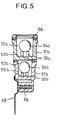
- the balancing apparatus is formed from an upper body 51a, a lower body 51b mounted to the underside of upper body 51a, and a cover 56 mounted on the upper end of upper body 51.
- Lower body 51b is fixedly coupled to the upper circumferential edge of a drum 58 of the washing machine by means of a screw 59.
- the bottoms of the chambers 52a,52b include a pair of upwardly projecting ribs 55a and 55b on which the balls 54a and 54b are supported.
- the ribs 55a and 55b are sloped in a similar fashion to the flat floor surfaces 43a and 43b of Figure 4.
- Surfaces 53a and 53b are made uniformly thick to prevent deformation during the injection molding process. If the annular fluid chambers 52a and 52b are also filled with liquid, it can flow smoothly while producing no impediment to the motion of balls 54a and 54b.
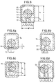
- reference letter a denotes the distance between the inner upper surface or ceiling 56 of annular fluid chamber 52 and the upper end of rib 55; b is the distance between each rib 55 and an adjacent upright side surface; c is the distance between the ribs, which define the chamber bottom; h is the height of rib 55; r is the radius of ball 54; t is the thickness of rib 55; and H is the height of the chamber.
- the width W of the chamber equals c + 2b +2t .
- equations 2 and 3 define necessary and satisfactory conditions for preventing the erratic motion of ball 54 on rib 55 caused by an increased frictional force which would otherwise occur if the ball 54 were to simultaneously contact surface 53 and wall surface 57.
- equations 4 and 5 define necessary and satisfactory conditions to prevent the balls 54 from being confined against rolling. In other words, it is preferable that all of the above equations are satisfied so that the ribs 55 promote the smooth motion of balls 54. In the embodiment described with reference to Figure 4, in which no ribs are formed, equations (4) and (5) above should be satisfied.
- FIG. 7 shows a schematic panoramic sectional view obtained by means of a vertical circumferentially extending section line through a balancing apparatus.
- the body 51 of the balancing apparatus has three axially-spaced annular fluid chambers 52a, 52b and 52c, and ribs 55a, 55b and 55c sloped in a 120° phase difference on respective surfaces 53a, 53b and 53c.
- Balls 54a, 54b and 54c are accommodated into respective annular fluid chambers 52a, 52b and 52c.
- embodiments of the invention may include at least two annular fluid chambers. Surfaces 53a, 53b and 53c may be sloped as in Figure 4 and with the ribs 55a, 55b and 55c omitted.
- the balancing apparatus includes a plurality of independently hollow annular cases 61a and 61b which are mounted to the upper circumferential edge of the drum of the washing machine.
- a plurality of balls 64a and 64b are disposed within the cases 61a and 61b.
- the outer peripheral wall surfaces 62a and 62b of respective annular cases 61a and 61b are sloped upwardly and outwardly by a predetermined angle with respect to the radial plane such that balls 64a and 64b can ascend along the outer peripheral wall surfaces 62a and 62b when the dehydrating drum is rotated faster than a prescribed speed.
- the flat floor surfaces 63a and 63b in contact with the balls 64a and 64b are sloped by a phase difference (e.g. 180° for two cases; 120° for three cases; 90° for four cases, etc.).
- FIG. 9 Another preferred embodiment of the present invention is illustrated in Figure 9 in which the balancing apparatus is formed from a plurality of independent hollow annular cases 71a and 71b which are mounted to the upper circumferential edge of the drum of the washing machine, and a plurality of balls 74a and 74b are disposed within the cases 71a and 71b.
- the outer peripheral wall surfaces 72a and 72b of respective annular cases 71a and 71b are sloped by a predetermined angle with respect to the radial plane such that balls 74a and 74b can ascend along outer peripheral wall surfaces 72a and 72b when the dehydrating tub is rotated faster than a prescribed speed.
- a pair of ribs 75a and 75b sloped at a phase difference for supporting balls 74a and 74b are formed on the surfaces 73a and 73b of respective annular cases 71a and 71b.
- annular cases of the balancing apparatus according to preferred embodiments of the present invention may further include oil of a certain viscosity.
- the present invention can be applied to other rotating bodies as well as the dehydrating tub of a washing machine.
- the uneven distribution of the balls toward one side with respect to the vibration induced during the initial rotating motion can be prevented, and the balls are uniformly distributed throughout the overall periphery to facilitate the balancing operation.
- the present invention when the present invention is applied to a clothes washing machine, the severe vibration occurring initially during the dehydrating operation is reduced and the vibrating time of the dehydrating tub is shortened thereby reducing noise generated by the washing machine and significantly enhancing its reliability.
- the present invention has a plurality of annular chambers for containing a greater number of balls and a larger amount of fluid, so it is especially useful in larger washing machines.
Landscapes
- Engineering & Computer Science (AREA)
- Textile Engineering (AREA)
- Main Body Construction Of Washing Machines And Laundry Dryers (AREA)
Applications Claiming Priority (4)
| Application Number | Priority Date | Filing Date | Title |
|---|---|---|---|
| KR9700208 | 1997-01-08 | ||
| KR9700209 | 1997-01-08 | ||
| KR1019970000208A KR100238646B1 (ko) | 1997-01-08 | 1997-01-08 | 볼 밸런서 |
| KR1019970000209A KR19980065311A (ko) | 1997-01-08 | 1997-01-08 | 볼 밸런서 |
Publications (1)
| Publication Number | Publication Date |
|---|---|
| EP0857807A1 true EP0857807A1 (de) | 1998-08-12 |
Family
ID=26632453
Family Applications (1)
| Application Number | Title | Priority Date | Filing Date |
|---|---|---|---|
| EP97307307A Withdrawn EP0857807A1 (de) | 1997-01-08 | 1997-09-19 | Waschmaschine |
Country Status (6)
| Country | Link |
|---|---|
| US (1) | US5857360A (de) |
| EP (1) | EP0857807A1 (de) |
| JP (1) | JPH10192586A (de) |
| CN (1) | CN1086758C (de) |
| BR (1) | BR9704698A (de) |
| MY (1) | MY117313A (de) |
Cited By (1)
| Publication number | Priority date | Publication date | Assignee | Title |
|---|---|---|---|---|
| EP2604736A1 (de) * | 2011-12-16 | 2013-06-19 | Samsung Electronics Co., Ltd | Stabilisator und Waschmaschine damit |
Families Citing this family (40)
| Publication number | Priority date | Publication date | Assignee | Title |
|---|---|---|---|---|
| US6082151A (en) * | 1997-08-21 | 2000-07-04 | Eti Technologies, Inc. | Balancing device for use on washing machines |
| CN1221965C (zh) * | 1997-09-25 | 2005-10-05 | 松下电器产业株式会社 | 盘片驱动装置 |
| US6219328B1 (en) * | 1997-10-31 | 2001-04-17 | Funai Electric Co., Ltd. | Disc rotating apparatus |
| KR100252124B1 (ko) * | 1997-12-31 | 2000-04-15 | 윤종용 | 자기보상형 밸런서 |
| SE520327C2 (sv) * | 1998-10-19 | 2003-06-24 | Skf Autobalance Systems Ab | Metod för förbalansering av en roterande trumma, som har en temporärt varierande obalans |
| KR100565709B1 (ko) * | 1998-11-04 | 2006-05-25 | 엘지전자 주식회사 | 세탁기의 언발란스 감지 방법 및 장치 |
| US6333912B1 (en) * | 1999-02-01 | 2001-12-25 | Samsung Electronics Co., Ltd. | Self-compensating dynamic ball balancer for disk player |
| US6550292B1 (en) * | 2000-04-03 | 2003-04-22 | Whirlpool Corporation | Dynamic balancer for an automatic washer |
| US6442782B1 (en) | 2000-04-27 | 2002-09-03 | Maytag Corporation | Ball balancing mechanism |
| US6568291B1 (en) * | 2000-10-05 | 2003-05-27 | William E. Inman | Shaftless gyrostabilizer |
| US6532422B1 (en) * | 2001-06-29 | 2003-03-11 | Honeywell International, Inc. | Simultaneous injection method and system for a self-balancing rotatable apparatus |
| KR20030048800A (ko) * | 2001-12-13 | 2003-06-25 | 엘지이노텍 주식회사 | 스핀들모터 |
| US7509825B2 (en) * | 2002-05-22 | 2009-03-31 | Dyson Technology Limited | Automatic balancing device |
| US7305905B2 (en) * | 2004-01-09 | 2007-12-11 | The Bergquist Torrington Company | Rotatable member with an annular groove for dynamic balancing during rotation |
| EP2354292B1 (de) | 2006-06-01 | 2018-04-11 | Samsung Electronics Co., Ltd. | Waschmaschine mit Ausgleichsregler |
| KR101273587B1 (ko) | 2006-06-01 | 2013-06-11 | 삼성전자주식회사 | 드럼세탁기 |
| KR101003352B1 (ko) * | 2006-06-01 | 2010-12-23 | 삼성전자주식회사 | 밸런서를 구비한 세탁기 |
| KR101267334B1 (ko) * | 2006-11-06 | 2013-05-23 | 삼성전자주식회사 | 세탁기의 볼 밸런서 제어방법 |
| KR100960068B1 (ko) * | 2006-11-10 | 2010-05-31 | 삼성전자주식회사 | 볼밸런서 및 이를 구비한 세탁기 |
| KR101356645B1 (ko) * | 2007-04-19 | 2014-02-03 | 삼성전자주식회사 | 밸런서와 이를 구비하는 드럼세탁기 |
| CN101575794B (zh) * | 2008-05-06 | 2012-06-27 | 海尔集团公司 | 一种方便从滚筒内取放洗涤衣物的滚筒洗衣机 |
| KR101417778B1 (ko) * | 2009-08-24 | 2014-07-09 | 삼성전자 주식회사 | 세탁기, 세탁기의 이너터브 및 그 조립방법 |
| KR20110057302A (ko) * | 2009-11-24 | 2011-06-01 | 삼성전자주식회사 | 유체 밸런서 및 이를 갖춘 세탁기 |
| WO2011115384A2 (ko) | 2010-03-15 | 2011-09-22 | 엘지전자 주식회사 | 세탁장치 및 그 제어방법 |
| US9428854B2 (en) | 2010-07-30 | 2016-08-30 | Haier Us Appliance Solutions, Inc. | Method and apparatus for balancing an unbalanced load in a washing machine |
| KR101607867B1 (ko) * | 2011-07-27 | 2016-04-01 | 삼성전자 주식회사 | 세탁기와 그 밸런서 |
| US20130227994A1 (en) * | 2012-03-02 | 2013-09-05 | General Electric Company | Appliance balance ring with fluid channels |
| CN102635666B (zh) * | 2012-04-18 | 2016-05-18 | 武汉包尼喜科技有限公司 | 热流变动自动平衡系统 |
| EP2708628B1 (de) * | 2012-09-12 | 2015-09-02 | Samsung Electronics Co., Ltd | Waschmaschine |
| US9169591B2 (en) * | 2012-09-14 | 2015-10-27 | Samsung Electronics Co., Ltd. | Washing machine with balancing device having fluid accommodation portion |
| KR101332285B1 (ko) * | 2013-02-20 | 2013-11-22 | 삼성전자주식회사 | 세탁기 |
| JP2015042247A (ja) * | 2013-07-24 | 2015-03-05 | パナソニックIpマネジメント株式会社 | ドラム式洗濯機 |
| JP6236626B2 (ja) * | 2013-11-19 | 2017-11-29 | パナソニックIpマネジメント株式会社 | ドラム式洗濯機 |
| DE112014003395T5 (de) * | 2013-07-24 | 2016-03-31 | Panasonic intellectual property Management co., Ltd | Trommelwaschmaschine |
| JP6205577B2 (ja) * | 2013-07-24 | 2017-10-04 | パナソニックIpマネジメント株式会社 | ドラム式洗濯機 |
| DE112014005270B4 (de) * | 2013-11-19 | 2020-03-19 | Panasonic Intellectual Property Management Co., Ltd. | Trommel-Waschmaschine |
| JP6236627B2 (ja) * | 2013-11-19 | 2017-11-29 | パナソニックIpマネジメント株式会社 | ドラム式洗濯機 |
| JP2015097600A (ja) * | 2013-11-19 | 2015-05-28 | パナソニックIpマネジメント株式会社 | ドラム式洗濯機 |
| US10266978B2 (en) * | 2015-07-29 | 2019-04-23 | Whirlpool Corporation | Laundry treating appliance |
| US20220364547A1 (en) * | 2016-03-07 | 2022-11-17 | Daniel Anthony Maiullo | Variable moment flywheel |
Citations (4)
| Publication number | Priority date | Publication date | Assignee | Title |
|---|---|---|---|---|
| DE1091525B (de) * | 1956-01-17 | 1960-10-27 | Bosch Gmbh Robert | Vorrichtung zum Ausgleichen der Unwucht von Waescheschleudern |
| JPS54120957A (en) * | 1978-03-13 | 1979-09-19 | Mitsubishi Electric Corp | Centrifugal dehydrator |
| GB2104553A (en) * | 1981-08-26 | 1983-03-09 | Tokyo Shibaura Electric Co | Balancer for use in centrifugal rotary machine |
| JPS59183846A (ja) * | 1983-03-31 | 1984-10-19 | Toshiba Corp | 遠心回転機用バランサ |
Family Cites Families (3)
| Publication number | Priority date | Publication date | Assignee | Title |
|---|---|---|---|---|
| JPS54140064A (en) * | 1978-04-24 | 1979-10-30 | Toshiba Corp | Dynamic balancing apparatus |
| JPS5837353A (ja) * | 1981-08-27 | 1983-03-04 | Toshiba Corp | 遠心回転機用バランサ |
| JPS58130092A (ja) * | 1982-01-29 | 1983-08-03 | 株式会社東芝 | 遠心回転機のボ−ルバランサ |
-
1997
- 1997-08-22 US US08/916,263 patent/US5857360A/en not_active Expired - Lifetime
- 1997-08-26 MY MYPI97003927A patent/MY117313A/en unknown
- 1997-09-12 BR BR9704698A patent/BR9704698A/pt not_active Application Discontinuation
- 1997-09-19 EP EP97307307A patent/EP0857807A1/de not_active Withdrawn
- 1997-10-09 CN CN97120027A patent/CN1086758C/zh not_active Expired - Fee Related
- 1997-11-26 JP JP9324798A patent/JPH10192586A/ja active Pending
Patent Citations (4)
| Publication number | Priority date | Publication date | Assignee | Title |
|---|---|---|---|---|
| DE1091525B (de) * | 1956-01-17 | 1960-10-27 | Bosch Gmbh Robert | Vorrichtung zum Ausgleichen der Unwucht von Waescheschleudern |
| JPS54120957A (en) * | 1978-03-13 | 1979-09-19 | Mitsubishi Electric Corp | Centrifugal dehydrator |
| GB2104553A (en) * | 1981-08-26 | 1983-03-09 | Tokyo Shibaura Electric Co | Balancer for use in centrifugal rotary machine |
| JPS59183846A (ja) * | 1983-03-31 | 1984-10-19 | Toshiba Corp | 遠心回転機用バランサ |
Non-Patent Citations (2)
| Title |
|---|
| PATENT ABSTRACTS OF JAPAN vol. 003, no. 144 (M - 082) 28 November 1979 (1979-11-28) * |
| PATENT ABSTRACTS OF JAPAN vol. 009, no. 041 (C - 267) 21 February 1985 (1985-02-21) * |
Cited By (2)
| Publication number | Priority date | Publication date | Assignee | Title |
|---|---|---|---|---|
| EP2604736A1 (de) * | 2011-12-16 | 2013-06-19 | Samsung Electronics Co., Ltd | Stabilisator und Waschmaschine damit |
| US9115782B2 (en) | 2011-12-16 | 2015-08-25 | Samsung Electronics Co., Ltd. | Ball balancer and washing machine having the same |
Also Published As
| Publication number | Publication date |
|---|---|
| CN1086758C (zh) | 2002-06-26 |
| US5857360A (en) | 1999-01-12 |
| BR9704698A (pt) | 1999-01-05 |
| JPH10192586A (ja) | 1998-07-28 |
| MY117313A (en) | 2004-06-30 |
| CN1187553A (zh) | 1998-07-15 |
Similar Documents
| Publication | Publication Date | Title |
|---|---|---|
| US5857360A (en) | Washing machine having a balancing apparatus employing movable balls | |
| EP0811717B1 (de) | Waschmachine mit Kugelvorrichtung zum Ausbalancieren | |
| US6082151A (en) | Balancing device for use on washing machines | |
| US6132354A (en) | Automatic ball balancer for rotating machine | |
| EP0808934A2 (de) | Waschmaschine | |
| EP2573249B1 (de) | Trommelwaschmaschine | |
| EP0607678B1 (de) | Auswuchtvorrichtung für eine automatische Waschmaschine | |
| EP0716177B1 (de) | Wäschetrommel einer Waschmaschine | |
| CN1091817C (zh) | 用于滚桶洗衣机的平衡装置 | |
| EP2604736A1 (de) | Stabilisator und Waschmaschine damit | |
| EP0810389A1 (de) | Auswuchteinrichtung | |
| EP1032778B1 (de) | Kugelausgleichseinrichtung | |
| JP2004519638A (ja) | 回転機構の釣り合いのための装置及び方法 | |
| KR0182129B1 (ko) | 볼밸런서를 갖는 세탁기 | |
| JP4509096B2 (ja) | 垂直ロータ用バランサ及びこれを利用した遠心分離機 | |
| WO1998001733A1 (en) | A method for controlling vibration amplitude in rotary systems | |
| JP3791176B2 (ja) | ボールバランサ及びボールバランサを装着した遠心分離機 | |
| KR19980065311A (ko) | 볼 밸런서 | |
| KR19980065310A (ko) | 볼 밸런서 | |
| KR100273366B1 (ko) | 세탁기의 원심균형조절장치 | |
| EP0740716B1 (de) | Dynamische auswuchtvorrichtung einer wäschewaschmaschine | |
| KR200145370Y1 (ko) | 드럼세탁기의 밸런싱장치 | |
| KR100295963B1 (ko) | 세탁기의볼밸런서 | |
| KR100292344B1 (ko) | 자기보상형밸런서 | |
| JPH0143178B2 (de) |
Legal Events
| Date | Code | Title | Description |
|---|---|---|---|
| PUAI | Public reference made under article 153(3) epc to a published international application that has entered the european phase |
Free format text: ORIGINAL CODE: 0009012 |
|
| AK | Designated contracting states |
Kind code of ref document: A1 Designated state(s): DE FR GB NL |
|
| AX | Request for extension of the european patent |
Free format text: AL;LT;LV;RO;SI |
|
| 17P | Request for examination filed |
Effective date: 19990111 |
|
| AKX | Designation fees paid |
Free format text: AT BE CH DE LI |
|
| RBV | Designated contracting states (corrected) |
Designated state(s): AT BE CH DE LI |
|
| RBV | Designated contracting states (corrected) |
Designated state(s): DE FR GB NL |
|
| 17Q | First examination report despatched |
Effective date: 19991223 |
|
| STAA | Information on the status of an ep patent application or granted ep patent |
Free format text: STATUS: THE APPLICATION IS DEEMED TO BE WITHDRAWN |
|
| 18D | Application deemed to be withdrawn |
Effective date: 20000401 |