EP0857848B1 - Verfahren und Vorrichtung zum Zusammenbauen von Isolierglasscheiben - Google Patents
Verfahren und Vorrichtung zum Zusammenbauen von Isolierglasscheiben Download PDFInfo
- Publication number
- EP0857848B1 EP0857848B1 EP98101674A EP98101674A EP0857848B1 EP 0857848 B1 EP0857848 B1 EP 0857848B1 EP 98101674 A EP98101674 A EP 98101674A EP 98101674 A EP98101674 A EP 98101674A EP 0857848 B1 EP0857848 B1 EP 0857848B1
- Authority
- EP
- European Patent Office
- Prior art keywords
- blanks
- glass plates
- glass
- insulating glazing
- assembly
- Prior art date
- Legal status (The legal status is an assumption and is not a legal conclusion. Google has not performed a legal analysis and makes no representation as to the accuracy of the status listed.)
- Expired - Lifetime
Links
- 238000000034 method Methods 0.000 title claims description 24
- 239000011521 glass Substances 0.000 claims abstract description 250
- 238000007789 sealing Methods 0.000 claims abstract description 38
- 125000006850 spacer group Chemical group 0.000 claims description 17
- 230000006835 compression Effects 0.000 claims description 8
- 238000007906 compression Methods 0.000 claims description 8
- 230000033001 locomotion Effects 0.000 claims description 8
- 150000001875 compounds Chemical class 0.000 claims description 4
- 238000006073 displacement reaction Methods 0.000 claims description 3
- 238000011144 upstream manufacturing Methods 0.000 claims 1
- 238000003825 pressing Methods 0.000 abstract description 69
- 238000004519 manufacturing process Methods 0.000 description 13
- 239000007789 gas Substances 0.000 description 10
- 230000013011 mating Effects 0.000 description 7
- 239000007799 cork Substances 0.000 description 3
- 239000000565 sealant Substances 0.000 description 3
- XKRFYHLGVUSROY-UHFFFAOYSA-N Argon Chemical compound [Ar] XKRFYHLGVUSROY-UHFFFAOYSA-N 0.000 description 2
- 238000005452 bending Methods 0.000 description 2
- 239000000853 adhesive Substances 0.000 description 1
- 230000001070 adhesive effect Effects 0.000 description 1
- 229910052786 argon Inorganic materials 0.000 description 1
- 230000003749 cleanliness Effects 0.000 description 1
- 238000011109 contamination Methods 0.000 description 1
- 230000007423 decrease Effects 0.000 description 1
- 230000001419 dependent effect Effects 0.000 description 1
- 238000011161 development Methods 0.000 description 1
- 230000018109 developmental process Effects 0.000 description 1
- 239000004033 plastic Substances 0.000 description 1
- 229920001021 polysulfide Polymers 0.000 description 1
- 239000005077 polysulfide Substances 0.000 description 1
- 150000008117 polysulfides Polymers 0.000 description 1
- 229920001169 thermoplastic Polymers 0.000 description 1
- 239000004416 thermosoftening plastic Substances 0.000 description 1
- 238000005406 washing Methods 0.000 description 1
Images





Classifications
-
- E—FIXED CONSTRUCTIONS
- E06—DOORS, WINDOWS, SHUTTERS, OR ROLLER BLINDS IN GENERAL; LADDERS
- E06B—FIXED OR MOVABLE CLOSURES FOR OPENINGS IN BUILDINGS, VEHICLES, FENCES OR LIKE ENCLOSURES IN GENERAL, e.g. DOORS, WINDOWS, BLINDS, GATES
- E06B3/00—Window sashes, door leaves, or like elements for closing wall or like openings; Layout of fixed or moving closures, e.g. windows in wall or like openings; Features of rigidly-mounted outer frames relating to the mounting of wing frames
- E06B3/66—Units comprising two or more parallel glass or like panes permanently secured together
- E06B3/673—Assembling the units
- E06B3/67365—Transporting or handling panes, spacer frames or units during assembly
-
- E—FIXED CONSTRUCTIONS
- E06—DOORS, WINDOWS, SHUTTERS, OR ROLLER BLINDS IN GENERAL; LADDERS
- E06B—FIXED OR MOVABLE CLOSURES FOR OPENINGS IN BUILDINGS, VEHICLES, FENCES OR LIKE ENCLOSURES IN GENERAL, e.g. DOORS, WINDOWS, BLINDS, GATES
- E06B3/00—Window sashes, door leaves, or like elements for closing wall or like openings; Layout of fixed or moving closures, e.g. windows in wall or like openings; Features of rigidly-mounted outer frames relating to the mounting of wing frames
- E06B3/66—Units comprising two or more parallel glass or like panes permanently secured together
- E06B3/673—Assembling the units
- E06B3/67365—Transporting or handling panes, spacer frames or units during assembly
- E06B3/67386—Presses; Clamping means holding the panes during assembly
-
- E—FIXED CONSTRUCTIONS
- E06—DOORS, WINDOWS, SHUTTERS, OR ROLLER BLINDS IN GENERAL; LADDERS
- E06B—FIXED OR MOVABLE CLOSURES FOR OPENINGS IN BUILDINGS, VEHICLES, FENCES OR LIKE ENCLOSURES IN GENERAL, e.g. DOORS, WINDOWS, BLINDS, GATES
- E06B3/00—Window sashes, door leaves, or like elements for closing wall or like openings; Layout of fixed or moving closures, e.g. windows in wall or like openings; Features of rigidly-mounted outer frames relating to the mounting of wing frames
- E06B3/66—Units comprising two or more parallel glass or like panes permanently secured together
- E06B3/673—Assembling the units
- E06B3/67339—Working the edges of already assembled units
- E06B3/67343—Filling or covering the edges with synthetic hardenable substances
- E06B3/67347—Filling or covering the edges with synthetic hardenable substances by extrusion techniques
-
- E—FIXED CONSTRUCTIONS
- E06—DOORS, WINDOWS, SHUTTERS, OR ROLLER BLINDS IN GENERAL; LADDERS
- E06B—FIXED OR MOVABLE CLOSURES FOR OPENINGS IN BUILDINGS, VEHICLES, FENCES OR LIKE ENCLOSURES IN GENERAL, e.g. DOORS, WINDOWS, BLINDS, GATES
- E06B3/00—Window sashes, door leaves, or like elements for closing wall or like openings; Layout of fixed or moving closures, e.g. windows in wall or like openings; Features of rigidly-mounted outer frames relating to the mounting of wing frames
- E06B3/66—Units comprising two or more parallel glass or like panes permanently secured together
- E06B3/673—Assembling the units
- E06B3/67365—Transporting or handling panes, spacer frames or units during assembly
- E06B3/67373—Rotating panes, spacer frames or units
-
- E—FIXED CONSTRUCTIONS
- E06—DOORS, WINDOWS, SHUTTERS, OR ROLLER BLINDS IN GENERAL; LADDERS
- E06B—FIXED OR MOVABLE CLOSURES FOR OPENINGS IN BUILDINGS, VEHICLES, FENCES OR LIKE ENCLOSURES IN GENERAL, e.g. DOORS, WINDOWS, BLINDS, GATES
- E06B3/00—Window sashes, door leaves, or like elements for closing wall or like openings; Layout of fixed or moving closures, e.g. windows in wall or like openings; Features of rigidly-mounted outer frames relating to the mounting of wing frames
- E06B3/66—Units comprising two or more parallel glass or like panes permanently secured together
- E06B3/673—Assembling the units
- E06B3/67365—Transporting or handling panes, spacer frames or units during assembly
- E06B3/67382—Transport of panes or units without touching the bottom edge
Definitions
- the first glass sheet in the assembly and pressing device encouraged, leaning against the fixed pressure plate; she will be in a predetermined Positioned, then the movable press plate of the first Approximated glass plate, it absorbs, takes it from the first press plate and remove her from this one.
- the first press plate is then free to the second, with the glass plate provided with the spacer, which is now inserted in the assembly and pressing device is conveyed until they match the first glass sheet dekkungs Dermatitis, or a predetermined Positioned, then the movable press plate of the first Approximated glass plate, it absorbs, takes it from the first press plate and remove her from this one.
- the first press plate is then free to the second, with the glass plate provided with the spacer, which is now inserted in the assembly and pressing device is conveyed until they match the first glass sheet dekkungs Dermatitis
- the Tact time is the time between the completion of two consecutive Insulating glass panes.
- the cycle time is through the slowest operations in an insulating glass production line, which are the assembly and pressing (especially when the assembly and Pressing device also for filling the insulating glass pane with a heavy gas as argon is used, see e.g. DE-38 32 836 A1 and the DE 40 22 185 A1) as well as the sealing process, in which in the edge joint bounded by the spacer and the two glass plates is a hardening one Plastic, usually a polysulfide, is filled (DE 28 16 437 C2, DE 28 46 785 C2).
- the present invention has for its object to provide a method and apparatus for assembling insulating glass panes, which can shorten the cycle time compared to conventional vertical production lines for insulating glass panes.
- single nozzles replace with two in matching Distance juxtaposed nozzles, which preferably at one common carrier, synchronously on the edge of the insulating glass panes moved along and synchronously fed with sealant, expediently from a common source with a common pump.
- the two nozzles are preferably cushioned individually so that they themselves clinging to the two insulating glass pane edges independently of each other can.
- the two insulating glass panes in the sealing station congruent are positioned and promoted, they could, if not a liner is present, leaving scratches on each other. Therefore it is planned that the two insulating glass blanks during sealing and in conveying in held the sealing station at a constant distance from each other become. This distance should be smaller than the thickness of the insulating glass panes, e.g. only 1 mm or 2 mm.
- Shims e.g. Cork tiles, on one of the insulating glass blanks glued.
- Such cork tiles are also useful when the insulating glass panes after sealing, be placed on transport racks and at each other lean.
- the required four glass panels are not individually consecutive transferred to the assembly and pressing device, but rather they are already pairwise parallel and congruent at a distance from each other positioned and positioned so the two glass panel pairs simultaneously transferred to the assembly and pressing device and therein simultaneously first joined together and then pressed, if necessary, even before the final Pressing filled with a heavy gas, especially after one of the in the DE 40 22 185 A1 and DE 38 32 836 A1 disclosed method.
- the positioning the glass panels parallel and congruent to each other, hereinafter also as Pairing may, prior to transfer into the assembly and pressing device take place while still in the assembly and pressing device the two previous glass panel pairs joined together, if necessary with a Heavy gas filled and pressed.
- the assembly and Pressing device is opened again and the two compressed insulating glass blanks have left the assembly and pressing device can the two subsequent glass panel pairs simultaneously in the assembly andshrinking device.
- the period from the beginning of the run up to the Beginning of the closing of the assembly and pressing device can be compared with the period of time for which disclosed in the DE-92 05 069 U Working method is required to be reduced to about 1/3 to 1/4.
- Corresponding decreases the cycle time of the assembly and pressing device of which depends on the cycle time of the insulating glass production line as a whole.
- the first two promoted one after the other on a horizontal conveyor Glass panels are stopped in predetermined positions and then together rotated by 180 °, but not one vertical axis, but one to them parallel axis, which is about the same angle as the supported glass sheets inclined to the vertical.
- 180 ° The first two glass sheets in their final position parallel to their starting position on a conveyor track parallel to its original conveyor track.
- In this Location is the support device, against which the first two Glass panels could lean in their initial position, not below, but above the glass panels, so that additional means are provided to the To hold glass panels on their outside or at their edges so they do not fall off. As a means.
- Suction conveyor belts as disclosed in EP-A-0 225 429, are suitable are; such suction conveyor belts can not only keep the glass panels hanging, but also further.
- suction conveyor belts can not only keep the glass panels hanging, but also further.
- the first two sheets of glass on her To hold edge one could use grooved rollers whose axes of rotation are oriented at right angles to the glass table running level and in their grooves, the glass panels engage with their upper and lower edges.
- the first two glass sheets by two horizontal lines of To support support rollers, which act on their later inner surface, namely along its lower and upper edge, where the glass panels after assembly Have contact with the spacer or with a sealing compound, that is, in a region in which originates from the contact with the support rollers Traces are harmless.
- These support rollers define the glass run level the second conveyor track.
- the third and fourth Glass panel (preferably carry a spacer) promoted in the turning station and be brought to coincide with the first two sheets of glass.
- the first conveyor is located at the stationary Press plate of the assembly and pressing device.
- To achieve one Parallel second conveyor track are the support and funding of the in the Turning station located second conveyor track continued in the assembly and Pressing device. If, for example, suction conveyors are used as conveying means, so you can the movable press plate of the assembly and pressing device Equip with such Saug consbändem, which from the rotary station take over the next two glass panels, fürfördem and thereby hold at the same time.
- you use in the turning station as preferred two support roller lines for supporting the first two glass panels on the upper and lower edge of its inner surface, then you can see these support roller lines continue into the nip of the assembly and pressing device.
- the two glass panel pairs can be consecutively in succession promote the assembly and pressing device.
- the shortest cycle time reached if you put the two glass panel pairs simultaneously in the turning station promotes. While in the assembly and pressing device, the two previous insulating glass panes can be assembled, the four subsequent Glass panels are already running into the turning station, paired in it and afterwards transferred in pairs simultaneously in the assembly and pressing device as soon as it is ready and open.
- first and the second glass panel can also move parallel to itself from the first lane to the second lane.
- This can be achieved, e.g. with two parallel on a common frame mutually mounted horizontal conveyors, which in particular is driven roller lines.
- Above each horizontal conveyor there is a support means, e.g. a row of freewheeling rollers, to which the glass plate standing on the relevant horizontal conveyor can lean.
- a support means e.g. a row of freewheeling rollers, to which the glass plate standing on the relevant horizontal conveyor can lean.
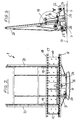
- FIG. 1 shows a turning station 1 and an assembly and pressing device 2.
- Glass panels 10, 10 ', 11, 11' are the turning station 1 by a horizontal conveyor 3, which consists essentially of a horizontal line of synchronously driven rollers 4, which are located near the bottom Edge of a designed as an air cushion wall support wall 5 are, which by a few degrees, in particular by 6 °, inclined to the vertical.
- a horizontal conveyor 3 which consists essentially of a horizontal line of synchronously driven rollers 4, which are located near the bottom Edge of a designed as an air cushion wall support wall 5 are, which by a few degrees, in particular by 6 °, inclined to the vertical.
- the Horizontal conveyor sets in different training through the turning station 1 and the assembly and pressing device 2 passes through in a horizontal conveyor 3 'with the same structure as him the horizontal conveyor 3 for has the conveying of assembled insulating glass blanks.
- the turning station has on a foot 6 a according to the inclination of the support wall 5 bogie 7 slightly inclined to the horizontal, on which two mutually parallel conveyor tracks 8 and 9 are provided, each consisting from a horizontal row of synchronously driven rollers 4 and 4 'with matching diameter whose axes of rotation in a common Plane lie, which runs at right angles to the support wall 5.
- 4 ' For supporting the glass sheets 10, 10 'and 11, 11' standing on the rolls 4, 4 'has the Turning instead of a fixed support wall support roll lines, one each Support roller line 12 and 13 in conjunction with the two rows of driven Rollers 4 and 4 ', wherein between each two driven rollers 4, 4' a Support roller is located, the slightly above the top of the driven up Rollers 4, 4 'protrudes.
- One of the two conveyor tracks 8 and 9 is still a third Support roller line 14 associated, which is substantially the same level with the Support roller rows 12 and 13 is, but is between these two, and Although so that the support rollers of the support roller line 14 in the spaces between engage the driven rollers 4, 4 'one of the two conveyor tracks.
- rollers 4 in one conveyor track 8 are separated from the rollers 4 'in the other Conveyor 9 drivable.
- the two electric motors intended for this purpose are designated 22 and 23.
- the bogie 7 runs with several wheels 24 on a circular path 25 on the Top of the foot 6.
- the rotary drive is via a z.
- the axis of rotation 26 of the turning station runs centrally in Regarding the length of the turning station and is close to the plane in which the Axle of the support rollers of the central support roller lines 14 and 17 are.
- the immediately following the turning station 1 subsequent assembly and pressing device 2 has on a frame 27 a fixed, designed as an air cushion wall Support wall 28, which also serves as a fixed press plate; she has the same inclination as the support wall 5 and as by the support roller 12 rows and 15, 13 and 16, respectively, defined glass sheet layers.
- a further support wall 29 is provided whose distance from the fixed Supporting wall 28 is variable by spindle drives 30; this mobile Supporting wall 29 is also formed as an air cushion wall and serves as a movable Press plate extending at right angles to the conveying direction 31
- Rails 32 is supported, these rails 32 in addition to the spindle drives 30 also serve as a parallel guide for the press plate 29.
- rollers 33 are provided which are so wide that they still can extend to below the edge of the movable press plate 29 when the press nip 34th so far is that in him the thickest in practice occurring insulating glass panes can be assembled.
- the rollers 33 are in flight the rollers 4 and 4 'of the rotating station. 1
- a bar 37 is motor up and down movable led, attached to which a further horizontal row of support rollers 38 is.
- Their axes are parallel to the press plates 28 and 29 and their common, the movable press plate 29 adjacent tangential plane is aligned with corresponding edges of flanges 39 (see Figures 5 and 6), which together with the support rollers 38, the run level for the first two Define glass panels 10 and 10 'in the assembly and pressing apparatus and the first two glass sheets 10, 10 'at the lower and upper edges on its inner side support.
- a lifting beam 40 is provided below the rollers 33, the lifting cam 41st carries, which engage in the space between two rollers 33 and on this standing glass panels 10, 10 'and 11, 11' can raise.
- the device can work as follows:
- a first glass sheet 10 is conveyed on the horizontal conveyor 3, passes in the turning station 1 on the rollers of the conveyor track 8 and is at the bottom Edge by the support rollers 12 and at the top by the support rollers 15th supported. It is stopped when it has a first vertical edge predetermined position near the front in the conveying direction 31 end of Turning station 1 has reached.
- the first glass sheet 10 follows on the same conveyor track 8, a second glass sheet 10 '; as soon as they enter the turning station with their trailing edge 1 is stopped, it is stopped in a predetermined second position and the Turning station is rotated by 180 °. It is then in the position that is in Figures 1 to 4 is shown.
- the first glass plate 10 and the second glass plate 10 ' fall with its upper edge of the support roller line 15 against the adjacent Support roller line 17.
- the drivable rollers 4 are during the rotational movement blocked so that the glass sheets 10 and 10 'can not run away.
- the horizontal conveyor 3 is a third with a Spacer 42 occupied glass panel 11 'on the conveyor track 9 in the turning station 1 in which it runs on the driven rollers 4 'and below is supported by the support rollers 13 and above by the support rollers 16.
- the third Glass panel 11 ' is so far promoted at stationary conveyor 8 until they congruent next to the second glass panel 10 'is.
- the third glass sheet 11 ' follows on the conveyor track 9, a fourth glass panel 11, which congruent with the first glass sheet 10 is positioned. From this position, the two glass panel pairs 10 and 11 and 10 'and 11', as soon as the assembly and Pressing device is ready and open, together at the same time in their Pressing gap 34 promoted.
- the driven rollers 4, 4 'and 33 are coincident a little adjusted in the direction of travel, that the glass panels against the stationary pressing plate 28 are guided with the result that the first two Glass panels 10 and 10 'with its lower edge in the direction of the support rollers fourteenth and finally against the flanges 39 are performed, whereas the third and fourth glass sheet 11, 11 'reliably in their by the support rollers 13 and 16 and defined by the front of the stationary press plate run level remain.
- the support rollers 38 in the assembly and pressing station 2 are accurate in the flight of the support rollers 17 of the rotating station. 1
- the two glass panel pairs 10 and 11 and 10 'and 11' are synchronously forward moved until they are stopped in a predetermined position (see Figure 1).
- the Glass panel pair 10 ', 11' is then located with its leading edges at the outlet end the assembly and pressing device, whereas the pair of glass sheets 10, 11 with its trailing edges at the inlet end of the assembly and pressing device 2 is located.
- the lifting bar 40 is raised and with them the Glass panels 10, 10 ', 11 and 11', so that their lower edge above the flanges 39 is located.
- the movable press plate 29 becomes the first two Glass plates 10 and 10 'driven to suck them, including the pressing plate 29 openings has, which are connected to the suction side of a blower.
- the insulating glass panes are to be filled with a heavy gas then that is in the same assembly and pressing device 2 possible.
- This can be the first glass panel 10 at its edge, which at the inlet end of the assembly and pressing device 2, are bent, while at the same time the second Glass panel 10 'at its edge, which at the outlet end of the assembly and Pressing device 2 is located, can be bent while the two glass plates 10 and 10 'remain sucked by the movable pressure plate 29.
- the assembly and Pressing device 2 is opened and the blanks are simultaneously on the Horizontal conveyor 3 'carried off.
- the bogie 7 turned back in the rotating station 1 by 180 ° and takes in the described Identify the next four sheets of glass in turntable 1 in the time span until the completion of the preceding in the assembly and pressing device 2 Assembly process congruently positioned (paired) and then ready to run into the assembly and pressing device 2.
- Insulating glass panes can also be produced with the devices described which are assembled from three sheets of glass. To do this first in the manner described from two glass sheets two insulating glass blanks assembled. Meanwhile, a fifth and a Sixth glass panel conveyed into the turning station, positioned as before the glass panels 10 and 10 'and then rotated together by 180 °. Once the two out of each two blanks formed blanks are assembled, they are from the Assembling and pressing device 2 conveyed out to the following Horizontal conveyor 3 'are stopped there and the first two glass panels 10 and 10 'provided with a further spacer. Meanwhile, the fifth and sixth glass plate on the second conveyor track 9 of the movable press plate 29 supplied.
- the mating station 44 has on a frame 45 two perpendicular to the conveying direction 31 extending rails 46 and 47, on which two horizontal conveyor 48 and 49 with parallel conveyor tracks 8 and 9 along the rails 46 and 47 are mounted displaceably.
- the conveyor tracks 8 and 9 can a have the conveyor tracks in the rotating station 2 ( Figure 4) corresponding structure with two rows of driven rollers 4 and 4 'and with two support roller rows 13 and 14; Because of closer details can therefore on the description of the Rotary station be referenced.
- Support rollers 13 and 14 are further support rollers 16 and 17 are provided, which form two horizontal upper support roller lines, which at the bottom of horizontal hollow profile strips 18 are mounted, passing through them transversely Arms 19 are connected to two columns 20 of the frame 45 and are guided from slidably.
- the columns 20 are a few degrees backwards inclined.
- This device operates e.g. as follows:
- the conveyor track 8 is aligned with the horizontal conveyor 3.
- a first Glass panel 10 'is promoted on the horizontal conveyor 3 arrives in the Pairing station 44 on the rollers of the conveyor track 8 and is at the bottom supported by the support rollers 14 and at the top by the support rollers 17.
- the first glass sheet 10 ' is conveyed to a first position in which her vertical front edge at the outlet end of the mating station 44 is located.
- the horizontal conveyors 48 and 49 are now moved together across the conveying direction 31, until instead of the conveyor track 8, the conveyor track 9 in the flight of the horizontal conveyor 3 is located.
- a third glass sheet 11 'and a following her fourth glass panel 11 coming from the horizontal conveyor 3 on the horizontal conveyor Pass 49 on which they are on the driven rollers 4 and at the bottom by the support rollers 13 and at the top by the support rollers 16 are supported.
- the glass sheets 11 'and 11, which both have a Wear spacers 42 are congruent in the mating station 44 the glass sheets 10 'and 10 positioned. This condition is shown in FIG.
- Figure 10 shows the assembly and pressing device 2 in the conveying direction 31 then an intermediate transport device 50 with the horizontal conveyor 3 'at the bottom of an air cushion wall formed support wall 51; followed by a station 52, in which distance tiles can be glued to an insulating glass blank; followed by a mating station 53, in which two identically sized insulating glass blanks can be arranged congruent side by side; followed by one Sealing station 54.
- the intermediate transport device 50 serves to remove the two components from the assembly and pressing device 2 coming insulating glass slices 55th to take and, if necessary. To park, as long as the subsequent station 52 still is not free.
- the station 52 is like the station 50 from a horizontal conveyor 3 '' with driven rollers at the bottom of a few degrees inclined backwards Air cushion wall 56.
- every second insulating glass blank 55 can be stopped be placed on its free outside some shims, e.g. out Cork, to stick.
- Station 53 like station 50, has a driven roller Horizontal conveyor 3 '' 'at the bottom of a slightly inclined rear air cushion wall 57, which opposite a lifter 58 is arranged, which one or more directed against the air cushion wall 57 sucker, with which is an insulating glass pane blank standing on the horizontal conveyor 3 '' ' 53 sucked, lifted off the horizontal conveyor 3 '' 'and the air cushion wall 57 can be removed.
- the sealing station 54 has two horizontal conveyors 59 and 60 at the bottom Edge of air cushion walls 61 and 62.
- the horizontal conveyors 59 and 60 not rows of driven rollers, but V-shaped arranged endless belts 63 and 64, which stretched over driven rollers 65 and 66 are.
- Such a horizontal conveyor is detailed in the EP 0 549 648 B1, which is hereby incorporated to avoid repetition Reference is made.
- a sealing head 68 is provided, which is connected to one of the Air cushion wall 61 perpendicular axis 69 is pivotable.
- the sealing head 68 carries two identical, juxtaposed nozzles 70 and 71, with a crowned front edge of the insulating glass blanks 55 can be applied to seal their edge joints 72 and 73. Between the nozzles 70 and 71 and the sealing head 68 are compression springs 74 and 75, for a resilient abutment of the nozzles 70 and 71 at the edge the insulating glass blanks 55 provide.
- the sealing head 68 can not pivoted only about the axis 69, but in the gap 67 between the two Air cushion walls 61 and 62 are moved parallel to these up and down.
- a feed line 76 leads into it, whereby the two Nozzles 70 and 71 are supplied with sealing compound at the same time.
- the two nozzles 70 and 71 are located on a common carrier 77th and can work with this to adapt to insulating glass blanks with a changed distance between the two glass sheets 10 and 11 or 10 ' and 11 'and / or with changed glass panel thicknesses.
- the section of the production line shown in FIGS. 10 and 11 operates eg. as follows:
- Two insulating glass blanks assembled in the assembling and pressing device 2 55 are out of this together on the intermediate transport device 50 promoted.
- the first of two insulating glass blanks 55 runs unprocessed by the station 52 in the station 53, is there in a predetermined position, preferably so that its front edge is located at the outlet end of the support wall 53 is there by the lifting device 58, lifted from the conveyor track 3 '' 'and more than its thickness removed from the air bag wall 57.
- the second, subsequent insulating glass blank 55 is stopped at station 52, with some shims 78 (see Figure 11) pasted and then further promoted in the station 53 to exactly the position at which previously the now hanging on the lifting device 58 first insulating glass blank was located, which is now on the horizontal conveyor 3 '' 'deferred and coincident with the already there standing second insulating glass blank 55 is positioned, the two Blanks are held by the spacer plate 78 at a distance.
- the two become one Pair of assembled insulating glass blanks 55 from station 53 transferred to the horizontal conveyor 59 and further to the horizontal conveyor 60 and with their vertical trailing edges at the inlet end of the horizontal conveyor 60 positioned.
- the two nozzles 70 and 71 First, the two rear edge joint sections sealed by the nozzles 70 and 71 from bottom to top along the edge of the insulating glass blanks along to be moved. Once they arrived at the back upper corner of the blanks are, the sealing head 68 is pivoted by 90 °, so that the nozzles 70 and 71 facing down, as shown in Figure 11.
- the two Insulating glass blanks 55 from the horizontal conveyor 60 on the horizontal conveyor 59 moves back until the nozzles 71 and 70 at the front upper corner of Arriving blanks.
- the movement of the blanks is then stopped, the nozzle head 68 again rotated by 90 ° and at the front edge of the Blanks moved down to fill the edge joint sections lying there.
- the nozzles 70 and 71 arrive at the front lower corner of the blanks 55, They are again rotated 90 °, after which their openings after pointing up, and now the two blanks from the horizontal conveyor 59 transferred to the horizontal conveyor 60, wherein the underlying edge joint sections to be sealed.
- the horizontal conveyors 59 and 60 can be equal to each other in thickness Insulating glass blanks 55 are set. So that the two Blanks only with their two outer glass panels 10 'and 11 on the conveyor belts 63, 64, as shown in Figure 11, the vertex 79 of the V-arrangement in the flight of the middle of the gap between the two blanks 55 lie. For this purpose, the V-arrangement in the direction of the axes 80 of the belt 63 carrying rollers 65 displaced. Because of closer details will open EP 0 549 648 B1.
Landscapes
- Engineering & Computer Science (AREA)
- Civil Engineering (AREA)
- Structural Engineering (AREA)
- Joining Of Glass To Other Materials (AREA)
- Securing Of Glass Panes Or The Like (AREA)
- Automobile Manufacture Line, Endless Track Vehicle, Trailer (AREA)
Description
- Figur 1
- zeigt eine Anordnung aus einer Drehstation und einer Zusammenbau- und Preßvorrichtung in der Draufsicht,
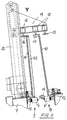
- Figur 2
- zeigt die Drehstation aus Figur 1 in der Vorderansicht,
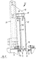
- Figur 3
- zeigt die Drehstation aus Figur 2 in einer Seitenansicht mit Blickrichtung in Förderrichtung,
- Figur 4
- zeigt das Detail Y aus Figur 3,
- Figur 5
- zeigt die Zusammenbau- und Preßvorrichtung aus Figur 1 in einer Seitenansicht mit Blickrichtung in Förderrichtung,
- Figur 6
- zeigt das Detail X aus Figur 5,
- Figur 7
- zeigt eine Anordnung aus einer Glastafeln quer versetzenden Station und einer Zusammenbau- und Preßvorrichtung in der Draufsicht,
- Figur 8
- zeigt die Glastafeln quer versetzende Station aus Figur 7 in einer Seitenansicht mit Blickrichtung in Förderrichtung,
- Figur 9
- zeigt das Detail Z aus Figur 8,
- Figur 10
- zeigt einen Abschnitt einer Fertigungslinie für Isolierglasscheiben in der Draufsicht, und
- Figur 11
- zeigt einen vertikalen Teilschnitt durch eine Versiegelungsstation, gemäß Schnittlinie XI-XI in Figur 10.
Claims (18)
- Verfahren zum Zusammenbauen und Versiegeln von Isolierglasscheiben aus Glastafein (10, 10', 11, 11') in einer wenige Grade gegen die Senkrechte geneigten Orientierung, durchdadurch gekennzeichnet, daß zwei deckungsgleiche Isolierglasscheibenrohlinge (55) deckungsgleich positioniert und gleichzeitig versiegelt werden.waagerechtes Fördern einer ersten und einer zweiten Glastafel (10,10') sowie einer dritten und einer vierten Glastafel (11, 11') in eine Zusammenbau- und Preßvorrichtung (2),paarweises Positionieren der deckungsgleichen Glastafeln (10, 10', 11, 11') in der Zusammenbau- und Preßvorrichtung (2),Zusammenfügen der Glastafelpaare (10, 11, 10', 11') zu zwei Isolierglasscheibenrohlingen durch Parallelverschieben einer der Glasplatten (11, 11') eines Paares von Glasplatten (10, 11,10', 11'),Verpressen der so gebildeten Rohlinge (55),Überführen der Rohlinge in eine Versiegelungsstation (54),Versiegeln der Isolierglasrohlinge, (55),
- Verfahren nach Anspruch 1, dadurch gekennzeichnet, daß die beiden Isolierglasscheibenrohlinge (55) beim Versiegeln in einem gleichbleibenden Abstand voneinander gehalten werden.
- Verfahren nach Anspruch 2, dadurch gekennzeichnet, daß der Abstand kleiner ist als die Dicke der Isolierglasscheiben.
- Verfahren nach einem der vorstehenden Ansprüche, dadurch gekennzeichnet, daß für das Versiegeln ein oder mehr als ein Paar Düsen (70, 71) verwendet werden, welche nebeneinander angeordnet synchron an den Rändem der beiden Isolierglasscheibenrohlingen (55) entlangbewegt werden.
- Verfahren nach Anspruch 4, gekennzeichnet durch die Verwendung von zwei auf einem gemeinsamen Träger (77) angeordneten Düsen (70, 71).
- Verfahren nach Anspruch 5, gekennzeichnet durch unabhängig voneinander abgefederten Düsen (70, 71).
- Vorrichtung zum Versiegeln der Randfuge (72, 73) von Isolierglasscheiben oder deren Rohlingen (55) mit einem Waagerechtförderer (59, 60), auf welchem die Isolierglasscheiben bzw. Rohlinge (55) hochkant stehen, und mit einer oberhalb des Waagerechtförderers (59, 60) angeordneten Stützeinrichtung (61, 62), an welche sich die auf dem Waagerechtförderer stehenden Isolierglasscheiben bzw. Rohlinge (55) anlehnen, in Kombination mit einer Düse (70, 71), welche am Rand der Isolierglasscheiben bzw. Rohlinge (55) entlang beweglich ist und mit Versiegelungsmasse gespeist wird, dadurch gekennzeichnet, daß zum Versiegeln von zwei deckungsgleich angeordneten Isolierglasscheiben oder deren Rohlingen (55) zwei nebeneinander angeordnete und getrennt abgefederte Düsen (70, 71) synchron an den Rändern der beiden Isolierglasscheiben bzw. Rohlinge (55) entlang beweglich sind und synchron mit Versiegelungsmasse gespeist werden.
- Vorrichtung nach Anspruch 7, dadurch gekennzeichnet, daß die beiden Düsen (70, 71) auf einem gemeinsamen Träger (77) angeordnet sind.
- Vorrichtung nach Anspruch 7 oder 8, dadurch gekennzeichnet, daß die Düsen (70, 71 )aus einer gemeinsamen Quelle gespeist werden.
- Vorrichtung nach einem der Ansprüche 7 bis 9 in Kombination mit einem davor angeordneten Waagerechtförderer (3''') für die Isolierglasscheibenrohlinge (55), und mit einer oberhalb des Waagerechtförderers (3''') angeordneten Stützeinrichtung (57) an welche sich die Isolierglasscheibenrohlinge (55) anlehnen, in Kombination mit einer Hebeeinrichtung (58), mit welcher ein Isolierglasscheibenrohling (55) vom Waagerechtförderer (3''') zeitweise abgenommen und wieder auf ihm abgestellt werden kann.
- Verfahren zum Zusammenbauen und Versiegeln von Isolierglasscheiben aus Glastafeln (10, 10', 11, 11') in einer wenige Grade gegen die Senkrechte geneigten Orientierung nach einem der Ansprüche 1 bis 6, durch folgende Schritte vor dem Überführen der Isolierglasrohlinge (55) in die Versiegelungsstation (54):waagerechtes Fördern einer ersten an einer ihrer Flächen abgestützten Glastafel (10) in jener Orientierung bis in eine bestimmte erste Stellung auf einer ersten Bahn (8),waagerechtes Fördern einer zweiten an einer ihrer Flächen abgestützten Glastafel (10') in jener Orientierung bis in eine bestimmte zweite Stellung auf der ersten Bahn (8),Verlagern der ersten und der zweiten Glastafel (10, 10') auf eine zur ersten Bahn parallele zweite Bahn (9),waagerechtes Fördern einer dritten an einer ihrer Flächen abgestützten Glastafel (11) in jener Orientierung auf der ersten Bahn (8) in jene bestimmte erste Stellung,waagerechtes Fördern einer vierten an einer ihrer Flächen abgestützten Glastafeln (11') in jener Orientierung auf der ersten Bahn (8) in jene bestimmte zweite Stellung, wobei entweder die erste und die zweite (10, 10') oder die dritte und die vierte Glastafel (11, 11') auf ihrer nicht abgestützten Fläche einen rahmenförmign Abstandhalter (42) trägt,Positionieren der beiden Glastafelpaare (10, 11, 10', 11') parallel und deckungsgleich mit Abstand voneinander,gleichzeitiges Überführen der so positionierten Glastafelpaare (10,11,10', 11') in eine Zusammenbau- und Preßvorrichtung (2),gleichzeitiges Zusammenfügen der beiden Glastafelpaar (10, 11, 10', 11') zu zwei Isolierglasscheibenrohlingen (55) durch Parallelverschieben der ersten und zweiten Glastafein (10, 10') oder der dritten und vierten Glastafeln (11, 11') undgleichzeitiges Verpressen der Rohlinge (55).
- Verfahren nach Anspruch 11, dadurch gekennzeichnet, daß die beiden Glastafelpaare (10, 11, 10', 11') gleichzeitig in eine Zusammenbau- und Preßstation (2) gefördert werden.
- Verfahren nach Anspruch 11 oder 12, dadurch gekennzeichnet, daß die Glastafeln (10, 10', 11, 11') beim Fördern an ihren in den Isolierglasscheiben einander abgewandten Flächen, nachfolgend als ihre Außenflächen bezeichnet, abgestützt werden,
daß die erste und die zweite Glastafel (10, 10') nach dem Erreichen ihrer ersten bzw. zweiten Stellung um eine zu jener Orientierung parallelen, vor der Flucht ihrer Innenflächen (das sind die in den Isolierglasscheiben einander zugewandten Flächen der Glastafeln) liegenden Achse um 180° verschwenkt werden, wodurch sie auf die zur ersten Bahn (8) parallele zweite Bahn (9) gelangen und an ihrem Rand oder an ihrer Außenseite gehalten werden. - Verfahren nach Anspruch 13, dadurch gekennzeichnet, daß die dritte und vierte Glastafel (11, 11') den Abstandhalter (42) tragen.
- Verfahren nach Anspruch 13 oder 14, dadurch gekennzeichnet, daß die erste Glastafel (10) beim Fördern an ihrem Rand gehalten und beim Zusammenfügen zur Isolierglasscheibe an ihrer Außenseite gehalten wird.
- Verfahren nach Anspruch 11 oder 12, dadurch gekennzeichnet, daß die erste und die zweite Glastafel (10, 10') gleichzeitig parallel zu sich selbst von der ersten Bahn (8) auf die zweite Bahn (9) verschoben werden.
- Verfahren nach einem der Ansprüche 1 bis 6, gekennzeichnet durch die Verwendung einer Vorrichtung
mit einem Waagerechtförderer (59, 60), der an einem endlosen Förderglied (63, 64) Auflageflächen hat, auf denen die Isolierglasscheiben (55) stehen,
und mit einer Stützeinrichtung (61, 62), welche sich oberhalb des Waagerechtförderers (59, 60) parallel zu diesem erstreckt und durch ein oder mehrere Stützelemente, an denen die auf dem Waagerechtförderer (59, 60) stehenden Isolierglasscheiben (55) anliegen, eine Scheibenlaufebene definiert, wobei die Auflageflächen in der Flucht zweier Ebenen liegen, die zur Förderrichtung (31) parallel sind und einen sich nach oben öffnenden Keil bilden, dessen Winkelhalbierende eine zur Scheibenlaufebene parallele Ebene ist,
und der Waagerechtförderer (59, 60) rechtwinklig zur Förderrichtung (31) parallel zu der Oberfläche jener Auflagefläche verschiebbar ist, welche der Scheibenlaufebene benachbart ist,
für das Fördern von zwei deckungsgleich angeordneten Isolierglasscheiben oder deren Rohlingen. - Verfahren nach einem der Ansprüche 1 bis 6, gekennzeichnet durch die Verwendung einer Vorrichtung
mit einem Waagerechtförderer, der in mehrere gesondert antreibbare Abschnitte unterteilt ist und in jedem seiner Abschnitte eine Trageinrichtung (4, 4') für das Aufstellen von Glastafeln (10, 10', 11, 11') mit ihrem unteren Rand sowie eine Stützeinrichtung (15, 16, 17) für das Abstützen der Glastafeln (10, 10', 11, 11') in einer wenige Grad gegen die Senkrechte geneigten Orientierung hat,
und mit einer Zusammenbau- und Pressvorrichtung (2) in einem Abschnitt des Waagerechtförderers mit einer ersten Pressplatte (28), welche jene Orientierung hat, und mit einer dazu parallelen, abstandsveränderlichen zweiten Pressplatte (29) mit Mitteln zum Festhalten einer ersten Glastafel (10, 10') an ihrer der ersten Pressplatte (28) zugewandten Oberfläche,
wobei ein vor der Zusammenbau- und Pressvorrichtung (2) liegender Abschnitt des Waagerechtförderers zwei zueinander parallele Förderbahnen (8, 9) in derselben Orientierung hat,
der Abschnitt mit den zwei Förderbahnen (8, 9) mitsamt den Stützeinrichtungen (15, 16, 17) um eine zwischen ihnen liegende Achse mit derselben Orientierung um 180 ° drehbar ist,
und zwischen den Stützeinrichtungen (15, 16) für die Außenfläche der Glastafeln (10, 10', 11, 11') und der zur Förderrichtung (31) parallelen Ebene durch die Achse Stützeinrichtungen (14, 17) zur Anlage am Glastafelrand oder zur Anlage an der Innenfläche der Glastafeln entlang ihrem Rand vorgesehen sind, von denen die für den oberen Glastafelrand bestimmten Stützeinrichtungen (17) in der Höhenlage verstellbar sind,
oder die Stützeinrichtungen für die Außenfläche der Glastafeln (10, 10', 11, 11') Mittel zum Ansaugen der Glastafein haben,
und wobei sich die beiden Förderbahnen (8, 9) bis in die Zusammenbau- und Pressvorrichtung (2) fortsetzen.
Applications Claiming Priority (2)
| Application Number | Priority Date | Filing Date | Title |
|---|---|---|---|
| DE19704878A DE19704878A1 (de) | 1997-02-10 | 1997-02-10 | Verfahren und Vorrichtung zum Zusammenbauen von Isolierglasscheiben |
| DE19704878 | 1997-02-10 |
Publications (3)
| Publication Number | Publication Date |
|---|---|
| EP0857848A2 EP0857848A2 (de) | 1998-08-12 |
| EP0857848A3 EP0857848A3 (de) | 2000-03-22 |
| EP0857848B1 true EP0857848B1 (de) | 2005-04-06 |
Family
ID=7819743
Family Applications (1)
| Application Number | Title | Priority Date | Filing Date |
|---|---|---|---|
| EP98101674A Expired - Lifetime EP0857848B1 (de) | 1997-02-10 | 1998-01-31 | Verfahren und Vorrichtung zum Zusammenbauen von Isolierglasscheiben |
Country Status (3)
| Country | Link |
|---|---|
| EP (1) | EP0857848B1 (de) |
| AT (1) | ATE292735T1 (de) |
| DE (2) | DE19704878A1 (de) |
Families Citing this family (6)
| Publication number | Priority date | Publication date | Assignee | Title |
|---|---|---|---|---|
| DE102005033040B3 (de) * | 2005-07-15 | 2007-03-22 | Lenhardt Maschinenbau Gmbh | Vorrichtung zum Zusammenbauen von Isolierglasscheiben, die mit einem von Luft verschiedenen Gas gefüllt sind |
| AT13586U1 (de) * | 2011-10-20 | 2014-04-15 | Inova Lisec Technologiezentrum | Versiegeln und Abstapeln |
| EP2796654B1 (de) | 2011-10-20 | 2019-07-31 | LISEC Austria GmbH | Verfahren zum Zwischenspeichern von Isolierglas-Rohlingen |
| RU2617979C1 (ru) | 2014-01-28 | 2017-04-28 | Лисец Аустриа Гмбх | Транспортировочное устройство |
| US11927052B2 (en) | 2016-08-11 | 2024-03-12 | Lisec Austria Gmbh | Method and device for sealing insulated glass blanks |
| DE102024120653A1 (de) * | 2024-07-19 | 2026-01-22 | Glaston Germany GmbH | Einrichtung und Verfahren zum unabhängigen Transportieren von zwei Glasscheiben in einer Scheibenbearbeitungsvorrichtung |
Family Cites Families (6)
| Publication number | Priority date | Publication date | Assignee | Title |
|---|---|---|---|---|
| DE2846785C2 (de) * | 1978-10-27 | 1984-07-19 | Karl 7531 Neuhausen Lenhardt | Vorrichtung zum automatischen Füllen der Randfugen von Zwei- oder Mehrfach- Isolierglasscheiben mit einem Dichtungsmittel unter Verwendung von Fülldüsen |
| DE2816437B1 (de) * | 1978-04-15 | 1979-08-16 | Karl Lenhardt | Vorrichtung zum automatischen Fuellen der Randfugen von Isolierglasscheiben mit einem Dichtungsmittel durch Fuellduesen |
| DE3217410C2 (de) * | 1982-05-08 | 1985-06-27 | Karl 7531 Neuhausen Lenhardt | Vorrichtung zum Füllen der Randfugen von Isolierglasscheiben mit einer Dichtmasse |
| DE3322801C2 (de) * | 1983-06-24 | 1985-08-14 | Szabo Maschinenbau GmbH & Co KG, 5608 Radevormwald | Verfahren und Anlage für die Randversiegelung von Isolierglaseinheiten |
| DE4029669C1 (de) * | 1990-09-19 | 1991-07-18 | Lenhardt Maschinenbau Gmbh, 7531 Neuhausen, De | |
| DE9205069U1 (de) * | 1992-04-11 | 1992-08-13 | Lenhardt Maschinenbau GmbH, 7531 Neuhausen | Vorrichtung zum Zusammenbauen von zwei Isolierglasscheiben die mit einem von Luft verschiedenen Gas gefüllt sind |
-
1997
- 1997-02-10 DE DE19704878A patent/DE19704878A1/de not_active Withdrawn
-
1998
- 1998-01-31 DE DE59812699T patent/DE59812699D1/de not_active Expired - Lifetime
- 1998-01-31 EP EP98101674A patent/EP0857848B1/de not_active Expired - Lifetime
- 1998-01-31 AT AT98101674T patent/ATE292735T1/de active
Also Published As
| Publication number | Publication date |
|---|---|
| EP0857848A3 (de) | 2000-03-22 |
| EP0857848A2 (de) | 1998-08-12 |
| ATE292735T1 (de) | 2005-04-15 |
| DE19704878A1 (de) | 1998-08-13 |
| DE59812699D1 (de) | 2005-05-12 |
Similar Documents
| Publication | Publication Date | Title |
|---|---|---|
| EP0213513B1 (de) | Vorrichtung zum Verbinden zweier Glastafeln zu einer randverklebten Isolierglasscheibe | |
| DE2905841C2 (de) | Verfahren und Anlage zur Herstellung einer Verbundplatte | |
| EP0222349B1 (de) | Vorrichtung für das schlupffreie Fördern von zwei Tafeln, insbesondere von Glastafeln | |
| EP1157184B1 (de) | Vorrichtung zum fördern von isolierglasscheiben | |
| EP2483504B1 (de) | Vorrichtung zum zusammenbauen eines fensterflügels mit integrierter isolierglasscheibe | |
| EP2802727B1 (de) | Vorrichtung und verfahren zum zusammenbau von isolierglasscheiben | |
| EP1730378B1 (de) | Verfahren zum positionieren von glastafeln in einer vertikalen zusammenbau- und pressvorrichtung für isolierglasscheiben | |
| EP2769043A2 (de) | Versiegeln und abstapeln | |
| DE4238254C2 (de) | Vorrichtung zum Fördern von Isolierglasscheiben | |
| DE4437998C2 (de) | Vorrichtung zum Zusammenbauen von Isolierglasscheiben | |
| DE102015118960A1 (de) | Verfahren und Vorrichtung zum Zusammenbauen von Glastafeln zu Isolierglasscheiben | |
| EP2483503B1 (de) | Verfahren zum zusammenbauen eines fensterflügels mit integrierter isolierglasscheibe | |
| EP0857849B1 (de) | Verfahren und Vorrichtung zum Zusammenbauen und Versiegeln von Isolierglasscheiben | |
| EP3133234A1 (de) | Verfahren und vorrichtung zum zusammenbauen von glastafeln zu isolierglasscheiben | |
| EP0857848A2 (de) | Verfahren und Vorrichtung zum Zusammenbauen von Isolierglasscheiben | |
| EP2390454B1 (de) | Vorrichtung zum Fördern von Isolierglasscheiben | |
| DE3400031C1 (de) | Vorrichtung zum Fördern von randverklebten Isolierglasscheiben | |
| DE19505771C1 (de) | Anlage zum Herstellen von Isolierglasscheiben mit Abstandhalter auf Kunststoffbasis | |
| EP1063383A2 (de) | Vorrichtung zum Zusammenbauen von Isolierglasscheiben, deren Innenraum mit einem Schwergas gefüllt ist | |
| AT13586U1 (de) | Versiegeln und Abstapeln | |
| EP4682094A1 (de) | Einrichtung und verfahren zum unabhängigen transportieren von zwei glasscheiben in einer scheibenbearbeitungsvorrichtung | |
| DE29903902U1 (de) | Vorrichtung zum Fördern von Isolierglasscheiben |
Legal Events
| Date | Code | Title | Description |
|---|---|---|---|
| PUAI | Public reference made under article 153(3) epc to a published international application that has entered the european phase |
Free format text: ORIGINAL CODE: 0009012 |
|
| AK | Designated contracting states |
Kind code of ref document: A2 Designated state(s): AT DE FR IT |
|
| AX | Request for extension of the european patent |
Free format text: AL;LT;LV;MK;RO;SI |
|
| PUAL | Search report despatched |
Free format text: ORIGINAL CODE: 0009013 |
|
| AK | Designated contracting states |
Kind code of ref document: A3 Designated state(s): AT BE CH DE DK ES FI FR GB GR IE IT LI LU MC NL PT SE |
|
| AX | Request for extension of the european patent |
Free format text: AL;LT;LV;MK;RO;SI |
|
| 17P | Request for examination filed |
Effective date: 20000905 |
|
| AKX | Designation fees paid |
Free format text: AT DE FR IT |
|
| 17Q | First examination report despatched |
Effective date: 20030813 |
|
| GRAP | Despatch of communication of intention to grant a patent |
Free format text: ORIGINAL CODE: EPIDOSNIGR1 |
|
| GRAS | Grant fee paid |
Free format text: ORIGINAL CODE: EPIDOSNIGR3 |
|
| GRAA | (expected) grant |
Free format text: ORIGINAL CODE: 0009210 |
|
| AK | Designated contracting states |
Kind code of ref document: B1 Designated state(s): AT DE FR IT |
|
| PG25 | Lapsed in a contracting state [announced via postgrant information from national office to epo] |
Ref country code: IT Free format text: LAPSE BECAUSE OF FAILURE TO SUBMIT A TRANSLATION OF THE DESCRIPTION OR TO PAY THE FEE WITHIN THE PRE;WARNING: LAPSES OF ITALIAN PATENTS WITH EFFECTIVE DATE BEFORE 2007 MAY HAVE OCCURRED AT ANY TIME BEFORE 2007. THE CORRECT EFFECTIVE DATE MAY BE DIFFERENT FROM THE ONE RECORDED.SCRIBED TIME-LIMIT Effective date: 20050406 |
|
| REF | Corresponds to: |
Ref document number: 59812699 Country of ref document: DE Date of ref document: 20050512 Kind code of ref document: P |
|
| PLBE | No opposition filed within time limit |
Free format text: ORIGINAL CODE: 0009261 |
|
| STAA | Information on the status of an ep patent application or granted ep patent |
Free format text: STATUS: NO OPPOSITION FILED WITHIN TIME LIMIT |
|
| 26N | No opposition filed |
Effective date: 20060110 |
|
| EN | Fr: translation not filed | ||
| PG25 | Lapsed in a contracting state [announced via postgrant information from national office to epo] |
Ref country code: FR Free format text: LAPSE BECAUSE OF FAILURE TO SUBMIT A TRANSLATION OF THE DESCRIPTION OR TO PAY THE FEE WITHIN THE PRESCRIBED TIME-LIMIT Effective date: 20050406 |
|
| PGFP | Annual fee paid to national office [announced via postgrant information from national office to epo] |
Ref country code: DE Payment date: 20101019 Year of fee payment: 14 Ref country code: AT Payment date: 20110120 Year of fee payment: 14 |
|
| PG25 | Lapsed in a contracting state [announced via postgrant information from national office to epo] |
Ref country code: DE Free format text: LAPSE BECAUSE OF NON-PAYMENT OF DUE FEES Effective date: 20120801 |
|
| REG | Reference to a national code |
Ref country code: DE Ref legal event code: R119 Ref document number: 59812699 Country of ref document: DE Effective date: 20120801 |
|
| REG | Reference to a national code |
Ref country code: AT Ref legal event code: MM01 Ref document number: 292735 Country of ref document: AT Kind code of ref document: T Effective date: 20120131 |
|
| PG25 | Lapsed in a contracting state [announced via postgrant information from national office to epo] |
Ref country code: AT Free format text: LAPSE BECAUSE OF NON-PAYMENT OF DUE FEES Effective date: 20120131 |