EP0857901A2 - Soupape - Google Patents
Soupape Download PDFInfo
- Publication number
- EP0857901A2 EP0857901A2 EP98100762A EP98100762A EP0857901A2 EP 0857901 A2 EP0857901 A2 EP 0857901A2 EP 98100762 A EP98100762 A EP 98100762A EP 98100762 A EP98100762 A EP 98100762A EP 0857901 A2 EP0857901 A2 EP 0857901A2
- Authority
- EP
- European Patent Office
- Prior art keywords
- valve
- valve seat
- valve housing
- recess
- housing
- Prior art date
- Legal status (The legal status is an assumption and is not a legal conclusion. Google has not performed a legal analysis and makes no representation as to the accuracy of the status listed.)
- Granted
Links
Images

Classifications
-
- F—MECHANICAL ENGINEERING; LIGHTING; HEATING; WEAPONS; BLASTING
- F16—ENGINEERING ELEMENTS AND UNITS; GENERAL MEASURES FOR PRODUCING AND MAINTAINING EFFECTIVE FUNCTIONING OF MACHINES OR INSTALLATIONS; THERMAL INSULATION IN GENERAL
- F16K—VALVES; TAPS; COCKS; ACTUATING-FLOATS; DEVICES FOR VENTING OR AERATING
- F16K1/00—Lift valves or globe valves, i.e. cut-off apparatus with closure members having at least a component of their opening and closing motion perpendicular to the closing faces
- F16K1/32—Details
- F16K1/34—Cutting-off parts, e.g. valve members, seats
- F16K1/42—Valve seats
Definitions
- the invention relates to a valve with a valve housing and at least one cooperating with a valve seat Valve body attached to an axially actuated valve stem is attached, the valve seat from a valve seat ring Has sealing material on which the valve body at closed valve sits sealingly.
- valves which, as in the present invention, for the Intended for use in the chemical and food industries hygiene and cleanliness play an important role. It is particularly important that there are none in the valves Impurities can settle easily and let it clean thoroughly and that it is above all reliable are. These valves are cleaned regularly Intervals with a cleaning liquid and / or a Disinfectant rinsed through, being a completed or only open space that is open on one side cannot be flushed could. In this case there is a risk of deposits and Given herds of germs. It is just as important that an exchange of spare parts quickly and easily can be.
- sealing rings of various types are made of sealing material used. On these sealing rings, which are between the valve housing, Valve housing cover, valve body and valve seat for Sealing is attached, there is another possibility contamination or leakage to the outside.
- valves as simple as possible and with a small number of Individual parts is held so that failures are avoided and possible repair or exchange work can be carried out easily and quickly.
- valves have an inserted valve seat ring, against which a valve body closes.
- This valve seat ring is housed in a recess in the valve body itself.
- the valve housing is on the side facing away from the valve seat Side mostly closed by a valve housing cover.
- This Connection is sealed by a sealing ring.
- On the valve seat side is usually by means of a third sealing ring a connecting piece is connected. So when building of a known valve three sealing rings necessary to Reliable valve to the outside and in the closed position to seal against flow. Is now with such a valve for example the valve seat ring, which is the most worn the valve housing cover must be replaced removed and the valve body removed from the valve chamber around the valve seat ring located in the valve body to reach.
- the object of the invention is a valve of the aforementioned Art to create that with little construction high reliability is to be produced, and also high hygienic requirements met.
- valve seat ring in the area of a Partition between the valve housing and a valve seat, the Parting line sealing, arranged, seals one and the same Sealing ring both permanently against the valve seat Valve housing as well as the valve body when closing the valve against the valve seat.
- the valve body and the valve seat is rotationally symmetrical.
- the valve body does not need to prevent it from turning around Axis of the valve stem to be secured.
- it is particularly favorable if the Valve body plate-shaped and in the area of its outer circumference is executed sealing. In comparison to the passage cross section the valve size is small. It also takes place the seal spreads to the greatest possible length, thereby the maximum load pressure on the valve seat ring as Force per area for the valve seat ring reduced.
- the parting line opens between the valve housing and valve seat in a recess that roughly opposite to the contact area with the valve body is arranged.
- the person sitting in it seals Valve seat ring and the joint between the valve housing and valve seat to the outside as well as the valve seat against the valve body.
- the recess undercut preferably on one side by an annular projection of the valve housing is undercut.
- the valve seat ring is firmly seated in of the recess and cannot stick through possible sticking are pulled out of the recess on the valve body.
- valve seat ring seals like a check valve from. It will then go towards the valve chamber pressed against the undercut and thus fulfills again its sealing function.
- a one-sided undercut through an annular projection of the valve housing easy insertion of the valve seat ring into the valve seat because the limitation of the recess through the undercut formed when installing the valve seat in the valve housing becomes.
- the cuts in the valve housing and valve seat, the form the recess, can preferably at least partially be rounded.
- the sealing ring is thus located on the valve housing or valve seat, and none Contamination rooms occur.
- the dimensions are or the cross section of the valve seat ring is larger than that Dimensions or the cross section of the recess, and the The valve seat ring is deformed in the recess appropriate.
- valve seat ring Due to the rotational symmetry described above, the Design of the valve seat ring in the manner of a made of sealing material existing round cord sealing ring, preferably with approximate circular cross section. In this way you can insert the valve seat ring into the recess insert. In addition, this is an advantageous form of a Sealing ring is due to a rounded cross section or circular cross section particularly resistant to Wear is.
- the valve seat ring can preferably be made of elastic material, e.g. Rubber. Are conceivable but also plastically deformable materials up to solid ones Materials such as PTFE (polytetrafluoroethylene).
- this Valve housing and the components that interact with it (Valve seat and / or valve housing cover) assigned to each other Areas formed in the form of centering steps are, preferably in each case a part of the first
- the step on the side of the valve housing is slightly chamfered can be. This makes the entire structure much more stable, because two valve parts can be inserted into each other gripping centering stages not radially against each other be moved.
- the fitting of the Valve simplified. At least by chamfering a part the first stage, for example on the side of the Valve housing, the respective valve part can be inserted more easily be centered by the bevel becomes.
- the connecting piece on the valve seat is particularly advantageous formed, preferably tubular with the outside conical connection flange. This will increase the number of Individual parts of the valve reduced and it does not result yet another connection that you can use for a seal must worry.
- valve stem is axially movable between a closed and an open position, preferably a bore through which the valve on the end facing away from the valve seat and on Valve housing attached valve housing cover this valve stem guide forms. This ensures that the Valve body is moved exactly against the valve seat to seal it reliably, and not by flowing through it Liquid is shifted sideways what the Sealing function would impair significantly.
- the valve housing with at least one is advantageous Connection made in one piece. On the one hand, that reduces again the number of individual parts and above all enables a secure connection to the each corresponding connection of the valve seat and Valve housing cover. You can use these connections Establish connections of the valve parts in a variety of ways, screwed or riveted flanges are conceivable, Union nuts and clamping sleeves, but also welding or gluing. In a particularly preferred Embodiment of the invention is a connection to the outside designed conical connection flange. On the one hand, this offers the advantages of using a conventional clamping ring with only a clamping screw quickly established connection that is permanent and can absorb loads. On the other hand the connection can be released just as quickly, if the valve is to be removed or maintenance work should make this necessary.
- a sealing ring attached, which is identical to the valve seat ring.
- This second recess is preferably also undercut, with the advantages of an undercut explained above for a recess in which a sealing ring is appropriate. Likewise, it can preferably be rounded off on the inside Incisions in the valve housing and valve housing cover with the same advantages as the other Recess.
- the invention creates a valve that consists of only few components and is easy to assemble and close is clean.
- the seal between the assembled and the components interacting with the valve actuation is partially combined with each other and the sealing points are reduced to a minimum.
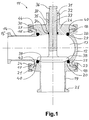
- valve 11 shows a valve 11 with a valve housing 12, which has the shape of a ball compressed at the poles and inside has a valve chamber 13 which also is shaped. On the left it goes into a tubular one Connection piece 14 over, the longitudinal axis of the Center of the valve housing 12 shows. The end of the connector 14 goes to the connection to other connections in a connecting flange 15.
- the connecting flange 15 is tapered on the outside.
- the valve housing is on the upper and lower side 12 open, the edges in each case in connection flanges 16 and 17 lead to the same and outward are conical.
- the connecting flanges 16 and 17 point on their side facing away from the valve chamber End faces, which are designed as centering steps 18. In each case, part of the valve chamber 13 counted first stage 40 slightly beveled.
- the opening and the connecting flanges 16 and 17 are radially symmetrical. Overall, the entire valve housing 12 is related its horizontal middle section plane symmetrical.
- a valve seat 20 is inserted into the lower opening is provided on a connecting piece 19 and radially after outside in a conical connection flange 21 passes. Furthermore, it has end faces that are considered too the centering stages 18 of the valve housing 12 corresponding Centering stages are formed, the two centering stages 18 interlock during assembly.
- the parting line 43 between the two centering stages 18 goes on the valve chamber side into a recess 22 through an inside directed ring projection 41 of the valve housing 12 and the Valve seat 20 is formed undercut.
- the annular projection 41 delimits an annular opening 42, which is narrower than the internal dimensions of the recess 22, the valve seat ring 23 is inserted into the recess 22.
- This is a round cord sealing ring made of plastic, rubber or other commonly used materials approximate circular cross section and stands with a Part of its cross section over the valve chamber 13 pointing side of the valve seat 20 over.
- the inner edges 45 and 46 of the recess 22 are of rounded design, that the inserted round cord sealing ring 23 smooth on them is present and no gaps between it and the valve housing 12 or valve seat 20 arise.
- valve housing 12 and valve seat 20 via a clamping ring 24 which over the two connecting flanges 17th and 21 is placed and matching the shape of the connecting flanges 17, 21 is conically shaped inside.
- a connecting flange 25 the identical to the connecting flange 15 of the other connecting piece 14 is.
- valve housing cover 26 used at the outer end of his Has a molded connecting flange 27 circumferentially. He also has end faces that go to the centering steps 18 of the valve housing 12 corresponding centering stages are trained. These two centering steps are effective when assembling one into the other. Between the two centering stages a parting line 44 runs to the valve chamber 13 towards an undercut recess 28 opens. The Undercut is due to the protruding edges of the Valve housing 12 and the valve housing cover 26 are formed. A sealing ring 29 is attached in the recess 28, which with the valve seat ring 23 as a round cord sealing ring approximate circular cross section. The connection between valve housing 12 and valve housing cover 26 via a clamping ring placed over the connecting flanges 16, 27 30 closed, which is identical to the lower clamping ring 24th
- valve housing cover goes up 26 into an extension 31, which is a considerably smaller Has cross section.
- Valve stem guide 32 Centrally through the valve housing cover 26 and the extension 31 runs a bore that the Valve stem guide 32 forms.
- the valve stem 33 axially movably mounted with the longitudinal axis of the connecting piece 19 escapes.
- the valve stem guide 32 near in the valve chamber 13 is on the inside with a Provide recess 34.
- the valve stem seal 35 inserted, past which the valve stem 33 passes.
- the valve stem 33 against the valve stem guide 32 sealed.
- the valve stem 33 provided with a radial constriction that the valve stem coupling 36 forms.
- valve stem 33 is not attached to one in the drawing Actuating unit shown, e.g. a pneumatic cylinder, connected, the valve stem 33 and thus that entire valve 11 actuated.
- Actuating unit shown e.g. a pneumatic cylinder
- the approach 31 is with a pointing diagonally down into the valve stem guide 32 reaching, bore 37, through which the valve stem guide 32 can be supplied with lubricant.
- the valve stem 33 has its in the valve chamber 13 located end of the valve body 38. This is plate-shaped executed and points to the valve seat ring 23 bevelled lower edge on which the contact area 39 to Valve seat ring 23 forms. This contact area 39 has the same angle to the horizontal as that assigned to it Edge of the valve seat 20.
- the diameter of the valve body 38 is dimensioned so that on the one hand it is still completely the Valve seat ring 23 covers, but on the other hand not radially reaches the valve housing 12.
- the diameter of the valve body 38 is less than the diameter of the top and the lower opening 42 in the valve housing 12 so that it on the one hand reached the sealing ring and then removed can.
- Valve body 38 guided within the annular projection 41.
- the upper recess 28 designed with rounded inner edges.
- valve seat ring 23 is in the Recess 22 placed in the valve seat 20 and the valve seat 20 with the connecting piece 19 in the opening provided introduced in the valve housing 12.
- the introduction is through the Centering steps 18 and especially by the bevel Part of the first stage 40 on the valve housing 12 side relieved, which automatically ensure that the valve seat 20 centrally in the lower opening in the valve housing 12 sits.
- the connecting flanges 17 and 21 of the Valve housing 12 and the valve seat 20 of the clamping ring 24 placed and by means of at least one screw in the circumferential direction tightened so that its diameter decreases and it extends radially inwards over the connecting flanges 17 and 21 pushes.
- Due to the conical shape becomes the force in the radial direction on the clamping ring 24 acts in an exclusively radial and an only split axial force component, the axial component the valve seat 20 with the valve housing 12 connects.
- valve seat ring 23 Because the cross section of the valve seat ring 23 is larger is as the recess 22 that receives it, it is through the walls of the recess 22 deformed under pressure. In this way it seals the connection of the valve seat 20 with the valve housing 12, i.e. the parting line 43, reliably. Since the recess 22 additionally through undercut the annular projection 41 of the valve housing 12 is, the valve seat ring 23 can not from its recess 22 out towards valve chamber 13 if he should adhere to the valve body 38, for example. Also in the event that in the valve chamber 13 compared to If the outside atmosphere is under pressure, the valve seat ring seals 23 still dependably.
- valve stem seal 35 When installing the valve housing cover 26, the Valve stem seal 35 in the recess provided 34 inserted. Just like when installing the valve seat 20 the sealing ring 29 placed in the part of the recess 28, which is formed in the valve housing cover 26. Then the Valve stem 33 with the molded valve body 38 through the Valve stem guide 32 guided, and the valve housing cover so equipped 26 into the upper opening of the valve housing 12 introduced.
- the centering stages 18 in turn provide for easy insertion and an exact centric fit Clamping ring 30 is on the two connecting flanges 16 and 27th placed and as described above with at least one clamping screw attracted, creating a form-fitting and tight Connection between valve housing 12 and valve housing cover 26 is manufactured.
- the recess 28 for the upper Sealing ring 29 is undercut, with the above described advantages that result from this.
- About the Connection flanges 15 and 25 at the ends of the two connecting pieces 14 and 19 can be used with the fully assembled valve Connected to further connections using tension rings will.
- valve stem coupling 36 With the help of the valve stem coupling 36, the valve stem 33 connected to an actuating unit, the valve stem 33 actuated in the axial direction. So that's the valve 11 fully assembled and ready for use.
- valve body 38 In the open position, the valve body 38 is in the valve chamber 13 moved up.
- the valve body should 38 and the opposite surface of the valve housing cover 26 so shaped that no completed or only one-sided open spaces arise in which Deposits that can not form from the flowing through Medium itself or from a flushed cleaning agent can be removed.
- the cross section of the valve seat ring 23 so that a sufficient part this cross-section over that assigned to the contact surface 39 Extends surface of the valve seat 20 against which then the contact surface 39 presses to the valve 11 under elastic Deformation of the valve seat ring 23 against flow to seal.
- the valve body 38 can be dimensioned such that it deforms under the normal closing force, but cannot be damaged by crushing. Possibly the valve closing path can be achieved by creating the Contact surface 39 of the valve body 38 on the opposite Area of the valve seat 20 may be limited.
Landscapes
- Engineering & Computer Science (AREA)
- General Engineering & Computer Science (AREA)
- Mechanical Engineering (AREA)
- Lift Valve (AREA)
- Taps Or Cocks (AREA)
Applications Claiming Priority (2)
| Application Number | Priority Date | Filing Date | Title |
|---|---|---|---|
| DE19704847A DE19704847A1 (de) | 1997-02-08 | 1997-02-08 | Ventil |
| DE19704847 | 1997-02-08 |
Publications (3)
| Publication Number | Publication Date |
|---|---|
| EP0857901A2 true EP0857901A2 (fr) | 1998-08-12 |
| EP0857901A3 EP0857901A3 (fr) | 1999-01-20 |
| EP0857901B1 EP0857901B1 (fr) | 2003-10-01 |
Family
ID=7819725
Family Applications (1)
| Application Number | Title | Priority Date | Filing Date |
|---|---|---|---|
| EP98100762A Expired - Lifetime EP0857901B1 (fr) | 1997-02-08 | 1998-01-17 | Soupape |
Country Status (2)
| Country | Link |
|---|---|
| EP (1) | EP0857901B1 (fr) |
| DE (2) | DE19704847A1 (fr) |
Cited By (7)
| Publication number | Priority date | Publication date | Assignee | Title |
|---|---|---|---|---|
| EP1223370A3 (fr) * | 2001-01-10 | 2003-05-02 | ITT Richter Chemie-Technik GmbH | Soupape d'arrêt avec des surfaces d'étanchéité coniques |
| US6891746B2 (en) | 2001-09-25 | 2005-05-10 | Hewlett-Packard Development Company, L.P. | Magneto-resistive device having soft reference layer |
| US8091861B2 (en) | 2006-11-20 | 2012-01-10 | Aker Subsea As | Valve for use in connection with oil production and gas production |
| EP2816265A1 (fr) * | 2013-06-18 | 2014-12-24 | Egmo Ltd. | Ensemble d'étanchéité de soupape |
| CN113309858A (zh) * | 2021-06-04 | 2021-08-27 | 浙江万龙机械有限公司 | 一种阀杆高频启闭防抖的氨用阀 |
| CN118482194A (zh) * | 2024-06-26 | 2024-08-13 | 凯喜姆阀门有限公司 | 一种阀座可自动对中的低温截止阀 |
| EP4682410A1 (fr) * | 2024-07-19 | 2026-01-21 | Swacrit Systems GmbH | Soupape |
Families Citing this family (1)
| Publication number | Priority date | Publication date | Assignee | Title |
|---|---|---|---|---|
| DE102004063973A1 (de) * | 2004-08-06 | 2006-06-14 | Elringklinger Ag | Dichtungsbaugruppe für ein Ventil |
Family Cites Families (4)
| Publication number | Priority date | Publication date | Assignee | Title |
|---|---|---|---|---|
| DE653689C (de) * | 1936-06-20 | 1937-12-01 | I G Farbenindustrie Akt Ges | Absperrventil |
| US2123477A (en) * | 1937-04-19 | 1938-07-12 | John M Sheedy | Valve |
| US2388710A (en) * | 1941-01-14 | 1945-11-13 | Hugh W Sanford | Valve |
| GB909405A (en) * | 1959-12-11 | 1962-10-31 | Burnett & Rolfe Ltd | Valves particularly for use with vessels employed in the brewing and dairy trades |
-
1997
- 1997-02-08 DE DE19704847A patent/DE19704847A1/de not_active Withdrawn
-
1998
- 1998-01-17 DE DE59809755T patent/DE59809755D1/de not_active Expired - Fee Related
- 1998-01-17 EP EP98100762A patent/EP0857901B1/fr not_active Expired - Lifetime
Cited By (8)
| Publication number | Priority date | Publication date | Assignee | Title |
|---|---|---|---|---|
| EP1223370A3 (fr) * | 2001-01-10 | 2003-05-02 | ITT Richter Chemie-Technik GmbH | Soupape d'arrêt avec des surfaces d'étanchéité coniques |
| US6891746B2 (en) | 2001-09-25 | 2005-05-10 | Hewlett-Packard Development Company, L.P. | Magneto-resistive device having soft reference layer |
| US8091861B2 (en) | 2006-11-20 | 2012-01-10 | Aker Subsea As | Valve for use in connection with oil production and gas production |
| EP2816265A1 (fr) * | 2013-06-18 | 2014-12-24 | Egmo Ltd. | Ensemble d'étanchéité de soupape |
| CN113309858A (zh) * | 2021-06-04 | 2021-08-27 | 浙江万龙机械有限公司 | 一种阀杆高频启闭防抖的氨用阀 |
| CN113309858B (zh) * | 2021-06-04 | 2023-06-23 | 浙江万龙机械有限公司 | 一种阀杆高频启闭防抖的氨用阀 |
| CN118482194A (zh) * | 2024-06-26 | 2024-08-13 | 凯喜姆阀门有限公司 | 一种阀座可自动对中的低温截止阀 |
| EP4682410A1 (fr) * | 2024-07-19 | 2026-01-21 | Swacrit Systems GmbH | Soupape |
Also Published As
| Publication number | Publication date |
|---|---|
| DE19704847A1 (de) | 1998-08-13 |
| DE59809755D1 (de) | 2003-11-06 |
| EP0857901B1 (fr) | 2003-10-01 |
| EP0857901A3 (fr) | 1999-01-20 |
Similar Documents
| Publication | Publication Date | Title |
|---|---|---|
| EP0968382B1 (fr) | Soupape a double siege nettoyable | |
| EP0625250B1 (fr) | Soupape a double siege | |
| DE60004838T3 (de) | Doppelsitzventil | |
| DE1650435A1 (de) | Kugelhahn | |
| EP0857901B1 (fr) | Soupape | |
| WO2009089853A1 (fr) | Dispositif d'entraînement d'une soupape à double siège présentant une fonction de nettoyage du siège | |
| EP2203667B1 (fr) | Soupape a double siege avec possibilite de nettoyage de siege et procede de nettoyage de cette soupape | |
| EP3730705A1 (fr) | Soupape sanitaire | |
| EP0983455B1 (fr) | Soupape a double siege de commutation sans fuites | |
| DE19720566C1 (de) | Doppelsitzventil | |
| DE19608792C2 (de) | Sitzreinigungsfähiges Doppelsitzventil | |
| DE3811937C2 (de) | Scheibenventil | |
| EP3688238B1 (fr) | Dispositif anti-reflux et séparateur de système en particulier pour le domaine de la lutte contre les incendies | |
| DE10163785A1 (de) | Einrichtung zum Zusammenschalten mehrerer hydraulischer oder pneumatischer Komponenten, insbesondere mehrerer Elektromagnetventile | |
| DE3003480C2 (fr) | ||
| DE4203723C2 (de) | Doppelsitzventil | |
| EP0711940B1 (fr) | Méthode pour manoeuvrer sans fuites une vanne à double siège; dispositif d'étanchéité utilisable à cet effet | |
| WO2005033565A1 (fr) | Dispositif repartiteur pour soupapes | |
| DE8033114U1 (de) | Rueckschlagventil | |
| DE102005005452A1 (de) | Systemtrenner | |
| AT395347B (de) | Einschraubventil | |
| DE3929431C2 (fr) | ||
| DE29721732U1 (de) | Rückschlagventil o.dgl. Rückflußverhinderer | |
| DE20019078U1 (de) | Anordnung einer Ringdichtung | |
| DE20303977U1 (de) | Absperrarmatur |
Legal Events
| Date | Code | Title | Description |
|---|---|---|---|
| PUAI | Public reference made under article 153(3) epc to a published international application that has entered the european phase |
Free format text: ORIGINAL CODE: 0009012 |
|
| AK | Designated contracting states |
Kind code of ref document: A2 Designated state(s): DE FR GB IT |
|
| AX | Request for extension of the european patent |
Free format text: AL;LT;LV;MK;RO;SI |
|
| PUAL | Search report despatched |
Free format text: ORIGINAL CODE: 0009013 |
|
| AK | Designated contracting states |
Kind code of ref document: A3 Designated state(s): AT BE CH DE DK ES FI FR GB GR IE IT LI LU MC NL PT SE |
|
| AX | Request for extension of the european patent |
Free format text: AL;LT;LV;MK;RO;SI |
|
| 17P | Request for examination filed |
Effective date: 19990708 |
|
| AKX | Designation fees paid |
Free format text: DE FR GB IT |
|
| 17Q | First examination report despatched |
Effective date: 20011228 |
|
| GRAG | Despatch of communication of intention to grant |
Free format text: ORIGINAL CODE: EPIDOS AGRA |
|
| GRAG | Despatch of communication of intention to grant |
Free format text: ORIGINAL CODE: EPIDOS AGRA |
|
| GRAH | Despatch of communication of intention to grant a patent |
Free format text: ORIGINAL CODE: EPIDOS IGRA |
|
| GRAH | Despatch of communication of intention to grant a patent |
Free format text: ORIGINAL CODE: EPIDOS IGRA |
|
| GRAA | (expected) grant |
Free format text: ORIGINAL CODE: 0009210 |
|
| AK | Designated contracting states |
Kind code of ref document: B1 Designated state(s): DE FR GB IT |
|
| PG25 | Lapsed in a contracting state [announced via postgrant information from national office to epo] |
Ref country code: IT Free format text: LAPSE BECAUSE OF FAILURE TO SUBMIT A TRANSLATION OF THE DESCRIPTION OR TO PAY THE FEE WITHIN THE PRE;WARNING: LAPSES OF ITALIAN PATENTS WITH EFFECTIVE DATE BEFORE 2007 MAY HAVE OCCURRED AT ANY TIME BEFORE 2007. THE CORRECT EFFECTIVE DATE MAY BE DIFFERENT FROM THE ONE RECORDED.SCRIBED TIME-LIMIT Effective date: 20031001 Ref country code: GB Free format text: LAPSE BECAUSE OF FAILURE TO SUBMIT A TRANSLATION OF THE DESCRIPTION OR TO PAY THE FEE WITHIN THE PRESCRIBED TIME-LIMIT Effective date: 20031001 Ref country code: FR Free format text: LAPSE BECAUSE OF FAILURE TO SUBMIT A TRANSLATION OF THE DESCRIPTION OR TO PAY THE FEE WITHIN THE PRESCRIBED TIME-LIMIT Effective date: 20031001 |
|
| REG | Reference to a national code |
Ref country code: GB Ref legal event code: FG4D Free format text: NOT ENGLISH |
|
| REF | Corresponds to: |
Ref document number: 59809755 Country of ref document: DE Date of ref document: 20031106 Kind code of ref document: P |
|
| PGFP | Annual fee paid to national office [announced via postgrant information from national office to epo] |
Ref country code: DE Payment date: 20040218 Year of fee payment: 7 |
|
| GBV | Gb: ep patent (uk) treated as always having been void in accordance with gb section 77(7)/1977 [no translation filed] |
Effective date: 20031001 |
|
| PLBE | No opposition filed within time limit |
Free format text: ORIGINAL CODE: 0009261 |
|
| STAA | Information on the status of an ep patent application or granted ep patent |
Free format text: STATUS: NO OPPOSITION FILED WITHIN TIME LIMIT |
|
| 26N | No opposition filed |
Effective date: 20040702 |
|
| EN | Fr: translation not filed | ||
| PG25 | Lapsed in a contracting state [announced via postgrant information from national office to epo] |
Ref country code: DE Free format text: LAPSE BECAUSE OF NON-PAYMENT OF DUE FEES Effective date: 20050802 |