EP0857902A2 - Back flow preventer - Google Patents
Back flow preventer Download PDFInfo
- Publication number
- EP0857902A2 EP0857902A2 EP98101244A EP98101244A EP0857902A2 EP 0857902 A2 EP0857902 A2 EP 0857902A2 EP 98101244 A EP98101244 A EP 98101244A EP 98101244 A EP98101244 A EP 98101244A EP 0857902 A2 EP0857902 A2 EP 0857902A2
- Authority
- EP
- European Patent Office
- Prior art keywords
- valve housing
- reducer
- backflow preventer
- filter
- lines
- Prior art date
- Legal status (The legal status is an assumption and is not a legal conclusion. Google has not performed a legal analysis and makes no representation as to the accuracy of the status listed.)
- Withdrawn
Links
Images


Classifications
-
- F—MECHANICAL ENGINEERING; LIGHTING; HEATING; WEAPONS; BLASTING
- F04—POSITIVE - DISPLACEMENT MACHINES FOR LIQUIDS; PUMPS FOR LIQUIDS OR ELASTIC FLUIDS
- F04B—POSITIVE-DISPLACEMENT MACHINES FOR LIQUIDS; PUMPS
- F04B53/00—Component parts, details or accessories not provided for in, or of interest apart from, groups F04B1/00 - F04B23/00 or F04B39/00 - F04B47/00
- F04B53/10—Valves; Arrangement of valves
-
- F—MECHANICAL ENGINEERING; LIGHTING; HEATING; WEAPONS; BLASTING
- F16—ENGINEERING ELEMENTS AND UNITS; GENERAL MEASURES FOR PRODUCING AND MAINTAINING EFFECTIVE FUNCTIONING OF MACHINES OR INSTALLATIONS; THERMAL INSULATION IN GENERAL
- F16K—VALVES; TAPS; COCKS; ACTUATING-FLOATS; DEVICES FOR VENTING OR AERATING
- F16K27/00—Construction of housing; Use of materials therefor
- F16K27/02—Construction of housing; Use of materials therefor of lift valves
- F16K27/0209—Check valves or pivoted valves
- F16K27/0227—Check valves or pivoted valves with the valve members swinging around an axis located at the edge of or outside the valve member
Definitions
- the invention relates to a backflow preventer with inlet and Drain connection for connecting pumps with lines and Hoses, in particular for connection to a pump suction line, consisting of a valve housing in which a spring-loaded Flap is arranged and each from a reducer, with the backflow preventer on lines, filter inserts or the like can be connected.
- the object of the present invention is therefore that described Avoid disadvantages and a backflow preventer like this to construct a pressure drop in the suction system of a pump is definitely avoided.
- the inventive design of the new backflow preventer consists essentially in that the reducer and Valve housing are integrally formed, with a common The central axis lies in the flow direction and is uniform Material for reducer and valve housing is used.
- the one-piece design prevents sealing problems and in addition, for a vortex-free flow worried because with those lying on a common central axis Components of the backflow preventer a smooth passage was created.
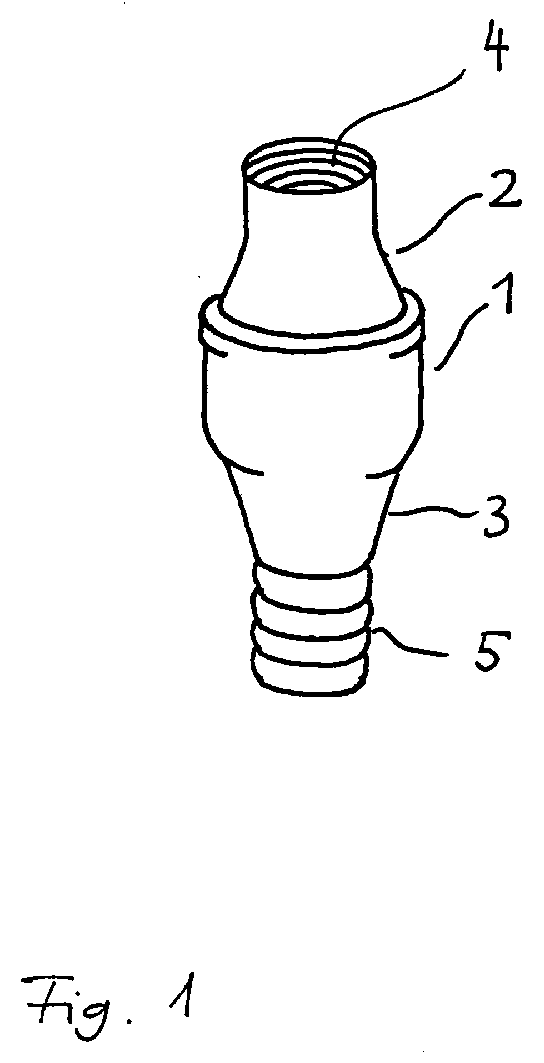
- valve housing 1 is on both sides enclosed by a reducer 2, 3.
- reducer 2 On the reducer 2 there is an internal thread 4 and on the reducer 3 a hose nozzle 5. These can be both metric and preferably have inch thread dimensions. 1 inch is common here Thread.
- the backflow preventer according to the invention is connected represented with a filter cloth.
- the backflow preventer consists of a valve housing 6, a reducer 7, a hose nozzle 8 and a filter unit made of filter fabric 9 and filter cover 10 with eyelet 11 is formed.
- the eyelet 11 is suitable for attaching a floating ball, can also be used to attach a Betelon rope for cleaning purposes be used.
Landscapes
- Engineering & Computer Science (AREA)
- General Engineering & Computer Science (AREA)
- Mechanical Engineering (AREA)
- Check Valves (AREA)
- Valve-Gear Or Valve Arrangements (AREA)
- Control Of The Air-Fuel Ratio Of Carburetors (AREA)
- Iron Core Of Rotating Electric Machines (AREA)
- Details Of Reciprocating Pumps (AREA)
Abstract
Die Erfindung betrifft einen Rückflußverhinderer mit Zu- und
Ablaufanschluß zur Verbindung von Pumpen mit Leitungen und
Schläuchen, üblicherweise bestehend aus einem Ventilgehäuse 1,
in dem eine federbelastete Klappe angeordnet ist sowie aus je
einem Reduzierstück 2, 3, mit dem der Rückflußverhinderer an
Leitungen, Filtereinsätzen oder dergleichen anschließbar ist.
Zur Vermeidung eines Druckabfalls im Ansaugsystem wird vorgeschlagen,
daß das Reduzierstück 2, 3 und das Ventilgehäuse 1
einstückig ausgebildet sind, wobei die gemeinsame Mittelachse in
Durchflußrichtung liegt und ein einheitliches Material für Reduzierstück
2, 3 und Ventilgehäuse 1 verwendet wird.
Description
Die Erfindung betrifft einen Rückflußverhinderer mit Zu- und Ablaufanschluß zur Verbindung von Pumpen mit Leitungen und Schläuchen, insbesondere zur Verbindung mit einer Pumpen-Saugleitung, bestehend aus einem Ventilgehäuse, in dem eine federbelastete Klappe angeordnet ist sowie aus je einem Reduzierstück, mit dem der Rückflußverhinderer an Leitungen, Filtereinsätzen oder dergleichen anschließbar ist.The invention relates to a backflow preventer with inlet and Drain connection for connecting pumps with lines and Hoses, in particular for connection to a pump suction line, consisting of a valve housing in which a spring-loaded Flap is arranged and each from a reducer, with the backflow preventer on lines, filter inserts or the like can be connected.
Derartige Rückflußverhinderer sind bereits bei verschiedenen Pumpensystemen verwendet worden. Ihre Aufgabe ist es, im Falle eines angeschlossenen Saugschlauchs eine Wassersäule bis zur Pumpe dauerhaft aufrechtzuhalten, damit nicht nach jedem Pumpenstart eine neue Wassersäule aufgebaut werden muß.Such check valves are already at various Pump systems have been used. Your job is in the event of a connected suction hose up to a water column Maintain the pump permanently, so that not after every pump start a new water column has to be built.
In der Praxis hat sich jedoch gezeigt, daß insbesondere nach längerer Standzeit die Wassersäule abgefallen war und daher vermutlich Undichtigkeiten im Ansaugbereich vorlagen.In practice, however, it has been shown that especially after the water column had fallen off for a longer period of time and therefore presumably there were leaks in the intake area.
Durch diese Undichtigkeiten und den damit verbundenen Druckabfall treten Zeitverzögerungen beim Start der Pumpenanlage auf. Bei häufigen Starts aus dem entleerten bzw. teilentleerten Zustand ist mit einem erhöhten Pumpenverschleiß zu rechnen, bedingt durch das Trockenlaufen und den ungleichmäßigen Belastungszustand der Pumpe.Because of these leaks and the associated drop in pressure there are time delays when starting the pump system. With frequent starts from the empty or partially empty state increased pump wear must be expected by running dry and uneven Load state of the pump.
Aufgabe der vorliegenden Erfindung ist es daher, die beschriebenen Nachteile zu vermeiden und einen Rückflußverhinderer derart zu konstruieren, daß ein Druckabfall im Ansaugsystem einer Pumpe mit Sicherheit vermieden wird.The object of the present invention is therefore that described Avoid disadvantages and a backflow preventer like this to construct a pressure drop in the suction system of a pump is definitely avoided.
Diese Aufgabe wird durch die im Hauptanspruch angegebenen Merkmale gelöst. Weitere Ausgestaltungen der Erfindung sind den Unteransprüchen zu entnehmen.This object is achieved by the features specified in the main claim solved. Further embodiments of the invention are the See subclaims.
Die erfindungsgemäße Ausbildung des neuen Rückflußverhinderers besteht im wesentlichen darin, daß das Reduzierstück und das Ventilgehäuse einstückig ausgebildet sind, wobei eine gemeinsame Mittelachse in Durchflußrichtung liegt und ein einheitliches Material für Reduzierstück und Ventilgehäuse verwendet wird. Durch die einstückige Ausbildung werden Dichtungsprobleme vermieden und zusätzlich wird für einen wirbelfreien Strömungsverlauf gesorgt, da mit den auf einer gemeinsamen Mittelachse liegenden Bauteilen des Rückflußverhinderers ein glatter Durchtrittskanal geschaffen wurde.The inventive design of the new backflow preventer consists essentially in that the reducer and Valve housing are integrally formed, with a common The central axis lies in the flow direction and is uniform Material for reducer and valve housing is used. The one-piece design prevents sealing problems and in addition, for a vortex-free flow worried because with those lying on a common central axis Components of the backflow preventer a smooth passage was created.
Weitere Einzelheiten sind den nachfolgenden Figurenbeschreibungen zu entnehmen. Es zeigen:
Figur 1- perspektivische Ansicht eines erfindungsgemäßen Rückflußverhinderers (Standardausführung)
Figur 2- perspektivische Ansicht eines erfindungsgemäßen Rückflußverhinderers in Kombination mit einer Filtereinheit.
- Figure 1
- perspective view of a backflow preventer according to the invention (standard version)
- Figure 2
- perspective view of a backflow preventer according to the invention in combination with a filter unit.
Wie aus Figur 1 zu entnehmen ist, wird das Ventilgehäuse 1 beidseitig
von einem Reduzierstück 2, 3 umschlossen. Am Reduzierstück
2 befindet sich ein Innengewinde 4 und am Reduzierstück 3
eine Schlauchtülle 5. Diese können sowohl metrische als auch
vorzugsweise Zollgewinde-Maße aufweisen. Üblich sind hier 1 Zoll
Gewinde. As can be seen from Figure 1, the
Wie bei der glatten Gehäuseform des erfindungsgemäßen Rückflußverhinderers zu erwarten war, wurde ein geringerer Durchlaßwiderstand beim Betrieb im Saug- und Druckbereich festgestellt.As with the smooth housing shape of the backflow preventer according to the invention a lower forward resistance was to be expected detected during operation in the suction and pressure area.
Dieses wiederum ist die Folge einer geringen Verwirbelung und damit von verringerten Leistungsverlusten. Bei der Optimierung konnten die Durchlaßwiderstände so bemessen werden, daß der Strömungsquerschnitt im Ventilgehäusebereich dem wirksamen Querschnitt im Reduzierstück entspricht.This in turn is the result of a slight swirl and thus reduced power losses. When optimizing could be measured so that the Flow cross section in the valve housing area the effective cross section in the reducer.
In Figur 2 ist der erfindungsgemäße Rückflußverhinderer in Verbindung
mit einem Filtergewebe dargestellt. Der Rückflußverhinderer
besteht aus einem Ventilgehäuse 6, einem Reduzierstück 7,
einer Schlauchtülle 8 und einer Filtereinheit, die aus Filtergewebe
9 und Filterdeckel 10 mit Öse 11 gebildet wird.In Figure 2, the backflow preventer according to the invention is connected
represented with a filter cloth. The backflow preventer
consists of a valve housing 6, a
Die Besonderheit dieser Kombination besteht darin, daß ein großer Filteransaugkorb verwendet werden kann, der zu einem beruhigten Ansaugen mit geringem Ansaugverlusten führt. Diese neuen Eigenschaften haben insbesondere für Regenwassersammelsysteme einen erheblichen Vorteil, da hiermit eine Verwirbelung der Sedimente vermieden werden kann und die Pumpenauslegung im Hinblick auf verringerte Leistungsanforderungen erfolgen kann.The peculiarity of this combination is that a large Filter suction basket can be used that leads to a calming Suction with low suction losses leads. These new ones Have properties in particular for rainwater collection systems a considerable advantage, since this creates a turbulence in the Sediments can be avoided and the pump design in view can be done on reduced performance requirements.
Die Öse 11 ist für die Befestigung einer Schwimmkugel geeignet,
kann aber auch zum Befestigen eines Betelon-Seiles für Reinigungszwecke
verwendet werden.The
Die Vorteile des erfindungsgemäßen Rückflußverhinderers sind daher in Verbindung mit der Filtereinheit darin zu sehen, daß erstmalig ein sicheres, relativ wartungsarmes und sehr effizient arbeitendes Ansaugsystem geschaffen wurde, mit dem eine große Ansaugoberfläche ohne die bisherigen Abdichtungsprobleme für die Wasserentnahme aus Zisternen, Regenwassersammelbehältern oder Teichen und Seen eingesetzt werden kann.The advantages of the backflow preventer according to the invention are therefore to be seen in connection with the filter unit in that for the first time a safe, relatively low-maintenance and very efficient working intake system was created with which a large Suction surface without the previous sealing problems for the Removing water from cisterns, rainwater collecting tanks or Ponds and lakes can be used.
Claims (4)
dadurch gekennzeichnet,
daß das Reduzierstück (2, 3) und das Ventilgehäuse (1) einstückig ausgebildet sind, wobei eine gemeinsame Mittelachse in Durchflußrichtung liegt und ein einheitliches Material für Reduzierstück (2, 3) und Ventilgehäuse (1) verwendet wird.Backflow preventer with inlet and outlet connection for connecting pumps with lines and hoses, in particular for connection to a pump suction line, consisting of a valve housing (1) in which a spring-loaded flap is arranged and a reducer (2, 3), with which the backflow preventer can be connected to lines, filter inserts or the like,
characterized,
that the reducer (2, 3) and the valve housing (1) are integrally formed, with a common central axis in the flow direction and a uniform material for the reducer (2, 3) and valve housing (1) is used.
dadurch gekennzeichnet,
daß als Material ein Edelstahlblech verwendet wird, das durch spanloses Umformen wie Tiefziehen, Drücken und Bördeln in eine Form für das Reduzierstück (2, 3) und das Ventilgehäuse (1) gebracht wird. Backflow preventer according to claim 1,
characterized,
that a stainless steel sheet is used as the material, which is brought into a shape for the reducer (2, 3) and the valve housing (1) by non-cutting shaping such as deep drawing, pressing and flanging.
dadurch gekennzeichnet,
daß an dem einen Reduzierstück (7) eine Schlauchtülle (8) und an der anderen Seite des Ventilgehäuses (6) eine Filtereinheit, bestehend aus Filtergewebe (9) und Filterdeckel (10) angeordnet ist.Backflow preventer according to one of the preceding claims,
characterized,
that on the one reducer (7) a hose nozzle (8) and on the other side of the valve housing (6) a filter unit consisting of filter fabric (9) and filter cover (10) is arranged.
dadurch gekennzeichnet,
daß das Filtergewebe (9) fest mit dem Ventilgehäuse (6) verbunden ist und der Filterdeckel (10) eine Öse (11) zur Befestigung einer Schwimmkugel aufweist.Backflow preventer according to one of the preceding claims,
characterized,
that the filter fabric (9) is firmly connected to the valve housing (6) and the filter cover (10) has an eyelet (11) for attaching a floating ball.
Applications Claiming Priority (2)
| Application Number | Priority Date | Filing Date | Title |
|---|---|---|---|
| DE29702036U | 1997-02-06 | ||
| DE29702036U DE29702036U1 (en) | 1997-02-06 | 1997-02-06 | Backflow preventer |
Publications (2)
| Publication Number | Publication Date |
|---|---|
| EP0857902A2 true EP0857902A2 (en) | 1998-08-12 |
| EP0857902A3 EP0857902A3 (en) | 1999-04-28 |
Family
ID=8035561
Family Applications (1)
| Application Number | Title | Priority Date | Filing Date |
|---|---|---|---|
| EP98101244A Withdrawn EP0857902A3 (en) | 1997-02-06 | 1998-01-24 | Back flow preventer |
Country Status (2)
| Country | Link |
|---|---|
| EP (1) | EP0857902A3 (en) |
| DE (1) | DE29702036U1 (en) |
Cited By (1)
| Publication number | Priority date | Publication date | Assignee | Title |
|---|---|---|---|---|
| US10344884B2 (en) | 2014-09-01 | 2019-07-09 | Danfoss A/S | Valve with a welded valve housing |
Families Citing this family (1)
| Publication number | Priority date | Publication date | Assignee | Title |
|---|---|---|---|---|
| CN112050069A (en) * | 2020-08-28 | 2020-12-08 | 中国航发贵阳发动机设计研究所 | Lubricating oil return filter with one-way valve |
Family Cites Families (9)
| Publication number | Priority date | Publication date | Assignee | Title |
|---|---|---|---|---|
| US3001546A (en) * | 1958-10-06 | 1961-09-26 | Clifford A Salisbury | Check valve |
| GB1031226A (en) * | 1963-02-27 | 1966-06-02 | Clapets T J Soc D | Improvements in and relating to non-return valves |
| US3417778A (en) * | 1967-10-05 | 1968-12-24 | Johannes B. Ratelband | Check valve with resilient seat means |
| US3604453A (en) * | 1969-10-24 | 1971-09-14 | Gray Tool Co | Check valve |
| FR2257056B1 (en) * | 1974-01-03 | 1976-11-26 | Staubli Sa Ets | |
| DE3212949C2 (en) * | 1982-04-07 | 1985-02-21 | Klein, Schanzlin & Becker Ag, 6710 Frankenthal | Spring loaded check valve |
| DE8520847U1 (en) * | 1985-07-19 | 1985-09-05 | GAT Grubenausbau GmbH, 5840 Schwerte | check valve |
| DE19512657A1 (en) * | 1995-04-05 | 1996-10-10 | Sempell Babcock Ag | Method for producing an essentially tubular housing which is closed on all sides |
| FR2738892B1 (en) * | 1995-09-15 | 1997-10-24 | Cahouet | ONE-WAY VALVE PROTECTED AGAINST SPONTANEOUS INFLAMMATION |
-
1997
- 1997-02-06 DE DE29702036U patent/DE29702036U1/en not_active Expired - Lifetime
-
1998
- 1998-01-24 EP EP98101244A patent/EP0857902A3/en not_active Withdrawn
Cited By (1)
| Publication number | Priority date | Publication date | Assignee | Title |
|---|---|---|---|---|
| US10344884B2 (en) | 2014-09-01 | 2019-07-09 | Danfoss A/S | Valve with a welded valve housing |
Also Published As
| Publication number | Publication date |
|---|---|
| EP0857902A3 (en) | 1999-04-28 |
| DE29702036U1 (en) | 1997-03-27 |
Similar Documents
| Publication | Publication Date | Title |
|---|---|---|
| DE3520263C2 (en) | Free flow pump | |
| DE69520952T2 (en) | AUTOMATIC POOL CLEANER AND COMPONENT COMPONENTS | |
| DE60113122T2 (en) | ROBOT FOR VACUUM CLEANING OF SWIMMING POOLS UNDER PRESSURE AND EXPERIENCE | |
| EP2275681A1 (en) | Roll pump | |
| CH633424A5 (en) | DEVICE FOR BLOCKING THE FOOT IN A SKI BOOT. | |
| DE69220187T2 (en) | Automatic pool cleaner | |
| CH655249A5 (en) | DEVICE FOR DEGASSING A LIQUID CIRCUIT. | |
| DE1808411A1 (en) | Pump set consisting of two pumps arranged in a housing | |
| EP0857902A2 (en) | Back flow preventer | |
| DE2442010A1 (en) | HYDRAULIC HEAD FOR AN INJECTION PUMP AND INJECTION PUMP EQUIPPED WITH THIS HYDRAULIC HEAD | |
| DE3519816C2 (en) | Impeller for pumps | |
| DE69710175T2 (en) | Vibration damper for pump systems for emptying ship containers | |
| AT396800B (en) | DEVICE FOR ELIMINATING PLUGS IN DRAIN PIPES | |
| DE202018106890U1 (en) | Device for wastewater treatment | |
| DE68902618T2 (en) | PUMP SYSTEM, IN PARTICULAR FOR IRRIGATION. | |
| DE19804680B4 (en) | Side channel or peripheral pump | |
| DE3339948C2 (en) | Circulation pump for water jets on bathtubs | |
| CH240031A (en) | Self-priming centrifugal pump. | |
| DE3432456C2 (en) | Pump for pumping a liquid or viscous medium | |
| EP0151688B1 (en) | Valve for the prevention of backflow of liquid and gaseous media | |
| DE1927502U (en) | MOTOR PUMP UNIT, IN PARTICULAR FOR OIL HEATING SYSTEMS. | |
| DE9203797U1 (en) | Drain centrifugal pump, especially for washing machines | |
| DE2303507C3 (en) | check valve | |
| DE736779C (en) | Device for venting and ventilating a conveyor pipe connected to a pump like a lifter | |
| DE1609166C (en) | Sewage elevator |
Legal Events
| Date | Code | Title | Description |
|---|---|---|---|
| PUAI | Public reference made under article 153(3) epc to a published international application that has entered the european phase |
Free format text: ORIGINAL CODE: 0009012 |
|
| AK | Designated contracting states |
Kind code of ref document: A2 Designated state(s): AT BE CH DE DK ES FI FR GB GR IE IT LI LU MC NL PT SE |
|
| AX | Request for extension of the european patent |
Free format text: AL;LT;LV;MK;RO;SI |
|
| PUAL | Search report despatched |
Free format text: ORIGINAL CODE: 0009013 |
|
| AK | Designated contracting states |
Kind code of ref document: A3 Designated state(s): AT BE CH DE DK ES FI FR GB GR IE IT LI LU MC NL PT SE |
|
| AX | Request for extension of the european patent |
Free format text: AL;LT;LV;MK;RO;SI |
|
| AKX | Designation fees paid | ||
| REG | Reference to a national code |
Ref country code: DE Ref legal event code: 8566 |
|
| STAA | Information on the status of an ep patent application or granted ep patent |
Free format text: STATUS: THE APPLICATION IS DEEMED TO BE WITHDRAWN |
|
| 18D | Application deemed to be withdrawn |
Effective date: 19991029 |