EP0857992B1 - Optisches System mit dezentriertem Prisma - Google Patents
Optisches System mit dezentriertem Prisma Download PDFInfo
- Publication number
- EP0857992B1 EP0857992B1 EP97107235A EP97107235A EP0857992B1 EP 0857992 B1 EP0857992 B1 EP 0857992B1 EP 97107235 A EP97107235 A EP 97107235A EP 97107235 A EP97107235 A EP 97107235A EP 0857992 B1 EP0857992 B1 EP 0857992B1
- Authority
- EP
- European Patent Office
- Prior art keywords
- optical system
- axis
- ray
- principal ray
- pupil
- Prior art date
- Legal status (The legal status is an assumption and is not a legal conclusion. Google has not performed a legal analysis and makes no representation as to the accuracy of the status listed.)
- Expired - Lifetime
Links
- 230000003287 optical effect Effects 0.000 title claims description 321
- 210000001747 pupil Anatomy 0.000 claims description 95
- 230000009471 action Effects 0.000 claims description 71
- 210000000887 face Anatomy 0.000 claims description 4
- 210000005252 bulbus oculi Anatomy 0.000 claims description 3
- 230000004075 alteration Effects 0.000 description 26
- 238000010586 diagram Methods 0.000 description 17
- 238000012937 correction Methods 0.000 description 13
- 238000006073 displacement reaction Methods 0.000 description 8
- 201000009310 astigmatism Diseases 0.000 description 5
- 239000000470 constituent Substances 0.000 description 5
- 210000001508 eye Anatomy 0.000 description 4
- 238000005259 measurement Methods 0.000 description 4
- 238000000926 separation method Methods 0.000 description 4
- 230000014509 gene expression Effects 0.000 description 3
- 210000003128 head Anatomy 0.000 description 3
- 239000000463 material Substances 0.000 description 3
- 230000000007 visual effect Effects 0.000 description 3
- 238000010276 construction Methods 0.000 description 2
- 230000002349 favourable effect Effects 0.000 description 2
- 238000003384 imaging method Methods 0.000 description 2
- 238000001746 injection moulding Methods 0.000 description 2
- 238000000034 method Methods 0.000 description 2
- 230000002123 temporal effect Effects 0.000 description 2
- 206010010071 Coma Diseases 0.000 description 1
- 230000005540 biological transmission Effects 0.000 description 1
- 230000008859 change Effects 0.000 description 1
- 238000007796 conventional method Methods 0.000 description 1
- 230000007423 decrease Effects 0.000 description 1
- 238000013461 design Methods 0.000 description 1
- 230000006866 deterioration Effects 0.000 description 1
- 239000006185 dispersion Substances 0.000 description 1
- 230000000694 effects Effects 0.000 description 1
- 238000011156 evaluation Methods 0.000 description 1
- 239000011521 glass Substances 0.000 description 1
- 238000005286 illumination Methods 0.000 description 1
- 239000004973 liquid crystal related substance Substances 0.000 description 1
- 238000004519 manufacturing process Methods 0.000 description 1
- 238000000465 moulding Methods 0.000 description 1
- 239000013307 optical fiber Substances 0.000 description 1
- 238000005498 polishing Methods 0.000 description 1
- 238000012545 processing Methods 0.000 description 1
- 230000009467 reduction Effects 0.000 description 1
- 230000000717 retained effect Effects 0.000 description 1
- 230000002441 reversible effect Effects 0.000 description 1
- 230000003595 spectral effect Effects 0.000 description 1
- 238000012546 transfer Methods 0.000 description 1
Images


Classifications
-
- G—PHYSICS
- G02—OPTICS
- G02B—OPTICAL ELEMENTS, SYSTEMS OR APPARATUS
- G02B5/00—Optical elements other than lenses
- G02B5/04—Prisms
-
- G—PHYSICS
- G02—OPTICS
- G02B—OPTICAL ELEMENTS, SYSTEMS OR APPARATUS
- G02B25/00—Eyepieces; Magnifying glasses
- G02B25/001—Eyepieces
Definitions
- the present invention relates to a decentered prism optical system and, more particularly, to a decentered prism optical system of excellent productivity which can be applied to an ocular optical system or an imaging optical system.
- decentered prism optical systems examples include those disclosed in Japanese Patent Application Unexamined Publication (KOKAI) Nos. 7-333551 and 8-234137.
- the present applicant has also proposed decentered prism optical systems in Japanese Patent Application Unexamined Publication (KOKAI) Nos. 8-320452 and 8-313829. Any of these known decentered prism optical systems uses a rotationally asymmetric surface configuration for a surface having a reflecting action.
- a first surface which is disposed at a side closer to a pupil and which has both transmitting and reflecting actions is formed from a rotationally asymmetric surface
- a second surface which is disposed at a side remote from the pupil and which has only a reflecting action is also formed from a rotationally asymmetric surface, e.g. an anamorphic surface or a toric surface. Therefore, when measurement is performed to see whether or not surface configurations have been finished in conformity to the design values to produce a desired optical system, surface accuracies cannot be measured by an interferometric or other similar method because of rotational asymmetry, and it is necessary to carry out measurement by using a three-dimensional coordinate measuring device.
- a typical three-dimensional coordinate measuring device measures coordinates of points in a point-by-point manner and therefore suffers from the problems that no sufficient measuring accuracy can be attained, and that measurement takes a great deal of time.
- a third surface having only a transmitting action is designed to be a rotationally symmetric surface.
- the third surface which has only a transmitting action, has a narrow effective surface area. Therefore, it is difficult to judge from only the third surface whether or not the whole optical system has been produced with the correct configuration.
- the first surface which is closer to the pupil and has both reflecting and transmitting actions, has a large effective surface area. Therefore, it is convenient if the first surface is used as a reference for judgment as to whether the whole optical system is distorted or not.
- an object of the present invention is to provide a decentered prism optical system wherein a first surface disposed at a side of the optical system closer to a pupil, which has both transmitting and reflecting actions and also has a wide effective area, is formed from a rotationally symmetric spherical or aspherical surface.
- the present invention provides a decentered prism optical system having at least three surfaces which are decentered with respect to each other, wherein the space between the at least three surfaces is filled with a transparent medium having a refractive index not smaller than 1.3.
- At least two of the at least three surfaces of the optical system are reflecting surfaces arranged so that at least two internal reflections take place in the optical system.
- the at least two reflecting surfaces are disposed such that light rays reflected by these surfaces do not intersect each other in the optical system.
- One of the at least two reflecting surfaces is a rotationally asymmetric surface having no axis of rotational symmetry in nor out of the surface, and at least one other of the reflecting surfaces is arranged such that at least an effective surface thereof, which is an area that transmits and/or reflects a bundle of light rays in the entire area of the effective surface, is formed from a rotationally symmetric surface having an axis of rotational symmetry in the effective surface.
- the decentered prism optical system may include at least a first surface, a second surface, and a third surface.
- the rotationally symmetric surface is formed as the first surface having both a transmitting action through which a bundle of light rays enters the optical system or exits therefrom after passing through it, and a reflecting action by which the ray bundle is bent in the optical system.
- the rotationally asymmetric surface is formed as the second surface disposed to face the first surface.
- the third surface has a transmitting action through which the ray bundle exits from the optical system after passing through it or enters it.
- the third surface is disposed to face in a direction approximately perpendicular to a direction in which the first and second surfaces face each other.
- the first surface should be formed such that a transmitting region and a reflecting region overlap each other in at least a region of an effective surface thereof, and that at least the reflecting action taking place in the region of the effective surface of the first surface where the transmitting and reflecting regions overlap each other should be total reflection.
- the present invention provides a decentered prism optical system having at least three surfaces decentered with respect to each other, wherein the space between the at least three surfaces is filled with a transparent medium having a refractive index not smaller than 1.3, and wherein a bundle of light rays from an image plane is received to form an exit pupil.
- the optical system has at least a first surface formed from a rotationally symmetric surface having both a transmitting action through which the ray bundle entering the optical system exits therefrom, and a reflecting action by which the ray bundle is bent in the optical system; a second surface formed from a rotationally asymmetric surface disposed to face the first surface and having an action by which the ray bundle entering the optical system is reflected toward the first surface in the optical system; and a third surface disposed to face the image plane and having an action through which the ray bundle from the image plane enters the optical system.
- the third surface is disposed to face in a direction approximately perpendicular to a direction in which the first and second surfaces face each other.
- the first surface has a convex surface directed toward the second surface.
- the first surface, the second surface and the third surface are arranged to constitute the optical system such that at least the ray bundle entering the optical system through the third surface passes through the inside of the optical system and is reflected by the first surface; the ray bundle reflected by the first surface passes through the inside of the optical system and is reflected by the second surface; the ray bundle reflected by the second surface exits from the first surface, which faces the second surface, toward the exit pupil.
- the first surface is tilted with respect to a straight line along which an axial principal ray passing through the center of the image plane of the optical system and reaching the center of the exit pupil travels after exiting from the first surface until it enters the exit pupil in a YZ-plane in which light rays are folded such that the distance from the exit pupil to the first surface in a direction parallel to the straight line is shorter at the image plane side of the straight line than at the side of the straight line remote from the image plane.
- the present invention provides a decentered prism optical system having at least three surfaces decentered with respect to each other, wherein the space between the at least three surfaces is filled with a transparent medium having a refractive index not smaller than 1.3, and wherein a bundle of light rays from a pupil plane is received to form an image plane.
- the optical system has at least a first surface formed from a rotationally symmetric surface disposed to face the pupil plane and having both a transmitting action through which the bundle of light rays from the pupil plane enters the optical system and a reflecting action by which the ray bundle is bent in the optical system; a second surface formed from a rotationally asymmetric surface disposed to face the first surface and having an action by which the ray bundle entering the optical system is reflected toward the first surface in the optical system; and a third surface disposed to face in a direction approximately perpendicular to a direction in which the first and second surfaces face each other and having a transmitting action through which the ray bundle entering the optical system exits toward the image plane.
- the first surface, the second surface and the third surface are arranged to constitute the optical system such that at least the ray bundle entering the optical system through the first surface is reflected by the second surface, which faces the first surface; the ray bundle reflected by the second surface is reflected by the first surface, which faces the second surface; and the ray bundle reflected by the first surface passes through the inside of the optical system and exits from the third surface toward the image plane.
- the first surface is tilted with respect to a straight line along which an axial principal ray passing through the center of the pupil plane of the optical system and reaching the center of the image plane travels after exiting from the pupil plane until it intersects the first surface in a YZ-plane in which light rays are folded such that the distance from the pupil plane to the first surface in a direction parallel to the straight line is shorter at the image plane side of the straight line than at the side of the straight line remote from the image plane.
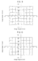
- Fig. 1 illustrates an optical ray trace of a three-surface prism, which has the simplest arrangement in the present invention, for the purpose of facilitating the understanding of the subject matter of the present invention.
- surfaces disposed along the optical path of a decentered prism optical system 7 consist essentially of three surfaces 3, 4 and 5.
- a bundle of light rays from an object first passes through a pupil 1 of the optical system 7 and enters the optical system 7 through a first surface 3 having both a transmitting action and a reflecting action.
- the incident light rays are reflected toward the pupil 1 by a second surface 4 which is disposed at a side of the optical system 7 remote from the pupil 1 and which has only a reflecting action.
- the reflected light rays are then reflected away from the pupil 1 by the first surface 3, which is disposed at a side of the optical system 7 closer to the pupil 1 and has both transmitting and reflecting actions.
- the reflected light rays pass through a third surface 5 which is disposed to face in a direction (Y-axis direction in the figure) approximately perpendicular to a direction (Z-axis direction in the figure) in which the first surface 3 and the second surface 4 face each other, and which has only a transmitting action, and reach an image plane 6 to form an image thereon.
- reference numeral 2 denotes an optical axis.
- the surface Nos. of the optical system are put in the order of tracing from the pupil 1 toward the image plane 6 as a general rule.
- Fig. 1 shows a decentered prism optical system 7 having four surfaces, i.e. a fourth surface 8 in addition to the first surface 3, the second surface 4, and the third surface 5.
- the fourth surface 8, which has a reflecting action, may be a rotationally symmetric spherical surface or a rotationally symmetric aspherical surface.
- Fig. 2(b) shows an example in which an identical surface is used to form both the first surface 3 and the third surface 5.
- the first surface which is disposed at the pupil side of the optical system and has both a transmitting action and a reflecting action
- the second surface which is disposed at the side of the optical system remote from the pupil and has only a reflecting action
- the reason for this is as follows: Assuming that a light ray emanating from the center of the object and passing through the pupil center to reach the center of the image plane is an axial principal ray, a point at which the axial principal ray is reflected by the first surface, which has both transmitting and reflecting actions, has a weaker refracting power than that of a point at which the axial principal ray is reflected by the second surface, which has only a reflecting action. Therefore, the amount of decentration aberration produced by the first surface owing to the decentration thereof is basically small, so that even if this surface is formed from a rotationally symmetric surface, the decentration aberrations can be corrected by another surface.
- the first surface 3 can be formed from a rotationally symmetric spherical surface or a rotationally symmetric aspherical surface, and if it is formed from a rotationally symmetric aspherical surface, it is desirable to satisfy the following condition (0-1) from the viewpoint of correcting decentration aberrations and chromatic aberrations with good balance: 5° ⁇ 30° where ⁇ is, as shown in Fig. 1, an angle of intersection between the optical axis 2 and a rotation center axis 12 passing through the center (vertex) of the rotationally symmetric aspherical surface.
- the angle ⁇ is not larger than the lower limit, i.e. 5°, the tilt of the first surface 3 with respect to the optical axis 2 becomes excessively small, so that it becomes impossible to satisfactorily correct decentration aberrations produced by the second surface 4. Consequently, it becomes necessary to form the first surface 3 from a rotationally asymmetric surface from the viewpoint of aberration correcting performance.
- the angle ⁇ is not smaller than the upper limit, i.e. 30°, the tilt of the first surface 3 with respect to the optical axis 2 becomes excessively large. Consequently, a large chromatic dispersion is introduced into a ray bundle passing through the first surface 3 (when it enters or exits from the optical system 7), causing the optical performance to be degraded.
- the rotation center axis 12 of a rotationally symmetric surface may be obtained by a line normal to a tangential line 11 at the center 10 in the YZ-plane (the section shown in Fig. 1; the definition of a coordinate system will be given later).
- the first surface 3 is formed from a rotationally symmetric spherical surface
- a point 13 at which an axial principal ray traveling along the optical axis 2 is internally reflected by the first surface 3 is defined as a center 10
- an angle of intersection between the optical axis 2 and the rotation center axis 12 passing through the point 13 is defined as the angle ⁇ [ ⁇ in Examples described later is the same as ⁇ in the condition (0-1)].
- angle ⁇ it is desirable for the angle ⁇ to satisfy the following condition (0-2) from the viewpoint of forming a decentered prism optical system having an even more excellent optical performance: 5° ⁇ 25°
- a Z-axis is defined by a straight line (which is coincident with the optical axis 2; which is an observer's visual axis when the decentered prism optical system is used as an ocular optical system) along which an axial principal ray passing through the center of the pupil 1 of the decentered prism optical system 7 and reaching the center of the image plane 6 (an image display device when the decentered prism optical system is used as an ocular optical system) travels after exiting from the pupil 1 until it intersects the first surface 3 of the decentered prism optical system 7.
- An axis perpendicularly intersecting the Z-axis in the decentration plane of each surface constituting the decentered prism optical system 7 is defined as a Y-axis.
- An axis perpendicularly intersecting both the Z- and Y-axes is defined as an X-axis.
- the center of the pupil 1 is defined as the origin of the coordinate system.
- the direction in which the axial principal ray emanates from the object point to reach the image plane is defined as the positive direction of the Z-axis.
- the direction in which the image plane 6 lies with respect to the optical axis 2 is defined as the positive direction of the Y-axis.
- a direction in which the X-axis constitutes a right-handed system in combination with the Y- and Z-axes is defined as the positive direction of the X-axis.
- At least one of the at least three surfaces constituting the decentered prism optical system should be formed from a rotationally symmetric surface.
- the decentered prism optical system according to the present invention will be described below as an image-forming optical system. It should be noted that the decentered prism optical system according to the present invention can be used as an ocular optical system by disposing the object point and the image point in reverse relation to the arrangement shown in Fig. 1 (i.e. an image display device is disposed in the image plane 6 shown in Fig. 1, and an observer's pupil is placed at the pupil 1). It is also possible to form an arrangement in which an image display device is disposed at the pupil 1, and an image of the image display device is observed from the image plane 6 side.
- an axial principal ray in the center of the image field is defined as 2 ⁇ ; a principal ray passing at the field angle zero in the direction X and at the maximum field angle in the direction +Y is defined as 1 ⁇ ; a principal ray passing at the field angle zero in the direction X and at the maximum field angle in the direction -Y is defined by 3 ⁇ ; a principal ray passing at the maximum field angle in the direction X and at the maximum field angle in the direction +Y is defined as 4 ⁇ ; a principal ray passing at the maximum field angle in the direction X and at the field angle zero in the direction Y is defined as 5 ⁇ ; and a principal ray passing at the maximum field angle in the direction X and at the maximum field angle in the direction -Y is defined as 6 ⁇ .
- An area where the principal rays 1 ⁇ to 6 ⁇ intersect each particular surface is defined as an effective area.
- the curvature of the surface in the direction of the X-axis, which perpendicularly intersects the Y-axis, in a plane containing a line normal to the surface at each of the six positions is also determined, and the curvatures in the X-axis direction are denoted by Cx1 to Cx6, respectively.
- the second surface in the present invention which has only a reflecting action, is characterized in that it is decentered and has a rotationally asymmetric surface configuration having no axis of rotational symmetry in nor out of the surface. Therefore, it is meaningless to deduce the focal length from a paraxial calculation. Accordingly, the focal length is defined as follows.
- Ray tracing is carried out with respect to a light ray which passes through a point that is a slight distance H (millimeter) away from the pupil center in the X-axis direction in parallel to an axial principal ray emanating from the center of the object point and passing through the center of the entrance pupil of the optical system, and which enters the optical system in parallel to the axial principal ray, and a value obtained by dividing the distance H by the NA of the light ray exiting from the optical system (i.e. the value of the sine of the angle formed between the light ray and the axial principal ray) is defined as the focal length Fx (millimeter) in the direction X of the entire optical system.
- a light ray which passes through a point that is the distance H (millimeter) away from the pupil center in the direction Y, and which enters the optical system in parallel to the axial principal ray is traced, and a value obtained by dividing the distance H by the NA of the light ray exiting from the optical system (i.e. the value of the sine of the angle formed between the light ray and the axial principal ray) is defined as the focal length Fy (millimeter) in the direction Y of the entire optical system.
- This condition relates to the aspect (length-to-width) ratio of the image. If FA is not larger than the lower limit of the condition (A-1), i.e. 0.7, the image decreases in size in the direction X. Consequently, when a square object is imaged, a rectangular image longer in the vertical (lengthwise) direction is undesirably formed. If FA is not smaller than the upper limit of the condition (A-1), i.e. 1.3, a square object is imaged undesirably as a rectangular image longer in the horizontal (breadthwise) direction.
- the most desirable value of FA is 1, as a matter of course. However, it is important in order to correct image distortion to make a correction with good balance within the range defined by the condition (A-1) in which FA deviates from 1 in view of the relationship to the higher-order coefficients of the surface.
- the second surface which has only a reflecting action, is a decentered surface. If this surface is formed from a rotationally symmetric surface, various aberrations, including image distortion, astigmatism, and coma, occur to a considerable extent, and it is impossible to favorably correct these aberrations. For this reason, it is important to form the second surface, which has only a reflecting action, from a rotationally asymmetric surface. If the second surface is formed from a rotationally symmetric surface, astigmatism produced by this surface becomes so large that it cannot be corrected by another surface. Therefore, in order to correct these aberrations, the second surface, which has only a reflecting action, is formed from a surface having only one plane of symmetry, and moreover, the above condition (D-1) is satisfied.
- the lower limit of the condition (D-1), i.e. 0.8, and the upper limit thereof, i.e. 1.2, are limits within which astigmatism can be prevented from occurring to a considerable extent.
- the second surface which has only a reflecting action, produces different aberrations for each image position. Therefore, each aberration must be corrected by changing the configuration of the reflecting surface.
- the amount of aberration subtly varies according to the position on the reflecting surface. Accordingly, it is important to satisfy the following conditions.
- the curvature in the direction X of that portion of the second surface having only a reflecting action at which the axial principal ray 2 ⁇ is reflected by the second surface is Cx2; the curvature in the direction X of the effective area at each of positions where the maximum field angle principal rays 1 ⁇ , 3 ⁇ to 6 ⁇ strike each surface is denoted by Cxn (n is 1, 3 to 6); of values each obtained by dividing the difference Cxn-Cx2 by the power Px in the direction X of the entire optical system, i.e.
- Cxn-Cx2/Px the maximum value is denoted by CxMaxE, and the minimum value is denoted by CxMinE; and of values each obtained by dividing the Y-direction curvature difference Cyn-Cy2 by the power Py in the direction Y of the entire optical system, i.e. (Cyn-Cy2)/Py, the maximum value is denoted by CyMaxF, and the minimum value is denoted by CyMinF.
- CxMinE or CyMinF is not larger than the lower limit of the condition (E-1) or (F-1), or CxMaxE of CyMaxF is not smaller than the upper limit of the condition (E-1') or (F-1'), the curvatures in the effective area become excessively different from each other, resulting in an excessively large variation in the curvature of the entire effective area of the second surface, which has the strongest refracting power in the optical system. Consequently, it becomes impossible to obtain or observe an image which is wide and flat over the entire field angle range.
- CyG denotes a value obtained by dividing the difference between the curvatures in the direction Y of the second surface at the upper and lower edges of the effective area, i.e. Cy1-Cy3, by Py, it is important to satisfy the following condition: -0.05 ⁇ CyG ⁇ 0.5
- This condition is necessary to satisfy in order to favorably correct vertical image distortions at the upper and lower edges of the image field. If CyG is not larger than the lower limit of the condition (G-1), i.e. -0.05, the magnification at the lower edge of the image field becomes undesirably small. If CyG is not smaller than the upper limit, i.e. 0.5, the magnification in the Y (vertical) direction on the image field becomes undesirably small in comparison to other portions of the image field, and the image is unfavorably distorted.
- a decentered prism optical system wherein a first surface having both reflecting and transmitting actions is formed from a rotationally symmetric surface to improve the productivity as in the present invention
- the third surface which is the closest to the image plane in the optical system and has only a transmitting action; otherwise, the image distortion cannot basically be corrected.
- the third surface which has only a transmitting action, mainly corrects field curvature. Therefore, if the second surface, which has only a reflecting action, does not satisfy the condition (G-1), it will become impossible for the entire optical system to correct field curvature and image distortion simultaneously.
- CxH denotes a value obtained by dividing the difference between the curvatures in the direction X of the second surface at the upper and lower edges of the effective area, i.e. Cx1-Cx3, by Px, it is important to satisfy the following condition: -0.01 ⁇ CxH ⁇ 0.1
- This condition is also necessary to satisfy in order to favorably correct horizontal image distortions at the upper and lower edges of the image field. If CxH is not larger than the lower limit of the condition (H-1), i.e. -0.01, the magnification at the lower edge of the image field becomes undesirably small. If CxH is not smaller than the upper limit, i.e. 0.1, the magnification in the X (horizontal) direction on the image field becomes undesirably small in comparison to other portions of the image field, and the image is unfavorably distorted in a trapezoidal shape.
- the third surface which is disposed to face the image plane and has only a transmitting action, should satisfy the following conditions.
- the Y-direction curvature in the negative direction of the Y-axis should become larger in the negative direction than the Y-direction curvature in the positive direction of the Y-axis.
- the positive direction of the Y-axis of a coordinate system that defines the third surface having only a transmitting action is taken in a direction toward the pupil, it is desirable that the X-direction curvature in the negative direction of the Y-axis should become larger in the negative direction than the X-direction curvature in the positive direction of the Y-axis.
- CxJ is not larger than the lower limit of the condition (J-1), i.e. 0, the X-direction curvature in the negative direction of the Y-axis does not become larger in the negative direction than the X-direction curvature in the positive direction of the Y-axis. Consequently, it becomes impossible to correct, with good balance, trapezoidal image distortion produced by the second surface, which has only a reflecting action. If CxJ is not smaller than the upper limit, i.e. 1, it is similarly impossible to favorably correct the trapezoidal image distortion. Thus, image distortion due to decentration cannot satisfactorily be corrected.
- the first surface, which has both reflecting and transmitting actions should be formed from a rotationally symmetric surface
- the second surface, which has only a reflecting action should be formed from a plane-symmetry three-dimensional surface which has no axis of rotational symmetry in nor out of the surface, and which has only one plane of symmetry.
- the present invention is applicable not only to an arrangement in which the second surface is formed from such a plane-symmetry three dimensional surface, but also to an arrangement in which the second surface is formed from an anamorphic surface having no axis of rotational symmetry in nor out of the surface, i.e. a rotationally asymmetric surface configuration having no axis of rotational symmetry in nor out of the surface.
- Fig. 1 is a ray path diagram illustrating the decentered prism optical system according to the present invention as arranged in the form of a three-surface prism.
- Figs. 2(a) and 2(b) are ray path diagrams illustrating other arrangements of the decentered prism optical system according to the present invention.
- Fig. 3 is a sectional view of a decentered prism optical system according to Example 1 of the present invention.
- Fig. 4 is a sectional view of a decentered prism optical system according to Example 2 of the present invention.
- Fig. 5 is a sectional view of a decentered prism optical system according to Example 3 of the present invention.
- Fig. 6 is a sectional view of a decentered prism optical system according to Example 4 of the present invention.
- Fig. 7 is an aberrational diagram showing image distortion in Example 1.
- Fig. 8 is an aberrational diagram showing image distortion in Example 2.
- Fig. 9 is an aberrational diagram showing image distortion in Example 3.
- Fig. 10 is an aberrational diagram showing image distortion in Example 4.
- Fig. 11 is a part of a spot diagram showing the condition of aberration correction in Example 1.
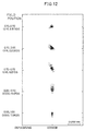
- Fig. 12 is another part of the spot diagram showing the condition of aberration correction in Example 1.
- Fig. 13 is the other part of the spot diagram showing the condition of aberration correction in Example 1.
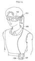
- Fig. 14 shows a head-mounted image display apparatus using the decentered prism optical system according to the present invention, which is fitted on an observer's head.
- Fig. 15 is a sectional view showing a part of the head-mounted image display apparatus in Fig. 14 which lies in the vicinity of the observer's head.
- Fig. 16 is a perspective view showing the arrangement of a camera using the decentered prism optical system according to the present invention.
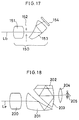
- Fig. 17 is a ray path diagram of a photographic optical system using the decentered prism optical system according to the present invention.
- Fig. 18 is a ray path diagram of a finder optical system using the decentered prism optical system according to the present invention.
- Fig. 19 shows the whole arrangement of an endoscope system.
- Fig. 20 is a sectional view of the distal end portion of a hard endoscope using the decentered prism optical system according to the present invention.
- Examples 1 to 4 of the decentered prism optical system according to the present invention will be described below.
- the center of a pupil 1 of an optical system 7 is defined as the origin of the optical system.
- An optical axis 2 is defined by a light ray which emanates from the center of an object and passes through the center (origin) of the pupil 1.
- a Z-axis is taken in a direction in which light rays travel from the pupil 1 along the optical axis 2.
- a Y-axis is taken in a direction which extends through the center of the pupil 1 at right angles to the Z-axis in a plane in which light rays are bent by the optical system 7.
- An X-axis is taken in a direction which extends through the center of the pupil 1 at right angles to both the Y- and Z-axes.
- a direction in which the Z-axis extends from the pupil 1 toward the optical system 7 is defined as a positive direction of the Z-axis.
- a direction in which the Y-axis extends from the optical axis 2 toward an image plane 6 is defined as a positive direction of the Y-axis.
- a direction in which the X-axis constitutes a right-handed system in combination with the Y- and Z-axes is defined as a positive direction of the X-axis. It should be noted that ray tracing is carried out in a direction in which light rays enter the optical system 7 from the object side of the pupil 1 of the optical system 7.
- each surface is given displacements in the X-, Y- and Z-axis directions of the vertex position of the surface from the center of the pupil 1, which is the origin of the optical system 7, and tilt angles of the center axis of the surface [the Z-axis in Eq.(b) shown below with respect to a three-dimensional surface] with respect to the X-, Y- and Z-axes ( ⁇ , ⁇ , and ⁇ , respectively).
- positive ⁇ and ⁇ mean counterclockwise rotation relative to the positive directions of the corresponding axes
- positive ⁇ means clockwise rotation relative to the positive direction of the Z-axis.
- the radius of curvature of each spherical surface, surface separation, refractive index of each medium, and Abbe's number are given according to the conventional method.
- An anamorphic surface is defined by the following equation.
- a straight line which passes through the origin of the surface configuration and which is perpendicular to the optical surface is defined as the axis of the anamorphic surface.
- Z (Cx ⁇ X 2 +Cy ⁇ Y 2 )/[1+ ⁇ 1-(1+Kx)Cx 2 ⁇ X 2 - (1+Ky)Cy 2 ⁇ Y 2 ⁇ 1/2 ] + ⁇ Rn ⁇ (1-Pn)X 2 +(1+Pn)Y 2 ⁇ (n+1)
- Z is the amount of deviation from a plane tangent to the origin of the surface configuration
- Cx is the curvature in the X-axis direction
- Cy is the curvature in the Y-axis direction
- Kx is the conical coefficient in the X-axis direction
- Ky is the conical coefficient in
- the configuration of a rotationally asymmetric surface is defined by the following equation.
- the Z-axis of the defining equation is the axis of the rotationally asymmetric surface.
- Z ⁇ n ⁇ m C nm X n Y n-m where ⁇ n indicates that n of ⁇ is from 0 to k, and ⁇ m indicates that m of ⁇ is from 0 to n.
- a plane-symmetry three-dimensional surface i.e. a rotationally asymmetric surface having only one plane of symmetry
- a rotationally asymmetric surface when symmetry produced by the plane of symmetry is to be obtained in the direction X, all terms with odd-numbered powers of X are made zero (for example, the coefficients of the terms with odd-numbered powers of X are set equal to zero).
- all terms with odd-numbered powers of Y are made zero (for example, the coefficients of the terms with odd-numbered powers of Y are set equal to zero).
- Plane-symmetry three-dimensional surfaces may also be defined by Zernike polynomials. That is, the configuration of a plane-symmetry three-dimensional surface may be defined by the following Eq.(c).
- the Z-axis of the defining Eq.(c) is the axis of Zernike polynomial.
- the plane-symmetry three-dimensional surface in the above equation is expressed as a surface which is symmetric with respect to the direction X.
- D m (m is an integer of 2 or higher) are coefficients.
- the configuration of a rotationally symmetric aspherical surface is defined by the following equation.
- the Z-axis of the defining equation is the axis of the rotationally symmetric aspherical surface.
- Z (Y 2 /R)/[1+ ⁇ 1-P(Y 2 /R 2 ) ⁇ 1/2 ] +A 4 Y 4 +A 6 Y 6 +A 8 Y 8 +A 10 Y 10 ...
- Y is a direction perpendicular to Z;
- R is a paraxial curvature radius;
- P is a conical coefficient; and
- a 4 , A 6 , A 8 , and A 10 are aspherical coefficients, respectively.
- the refractive index is expressed by the refractive index for the spectral d-line (wavelength: 587.56 nanometers). Lengths are given in millimeters.
- Figs. 3 to 6 are sectional views of Examples 1 to 4, taken along the YZ-plane containing the optical axis 2 of the decentered prism optical system 7.
- the decentered prism optical system 7 according to any of Examples 1 to 4 has three surfaces 3, 4 and 5 as in the case of Fig. 1.
- the space between the three surfaces 3 to 5 is filled with a transparent medium having a refractive index larger than 1.3.
- a bundle of light rays from an object first passes through the pupil 1 of the optical system 7 along the optical axis 2 and enters the optical system 7 through the first surface 3, which has both transmitting and reflecting actions.
- the incident light rays are reflected toward the pupil 1 by the second surface 4, which is disposed at a side of the optical system 7 remote from the pupil 1 and has only a reflecting action.
- the reflected rays are reflected by the first surface 3 so as to travel away from the pupil 1.
- the reflected rays pass through the third surface 5, which has only a transmitting action, and reach the image plane 6 where the rays form an image.
- the first surface 3 is a decentered spherical surface having a concave surface directed toward the pupil 1.
- the first surface 3 is a rotationally symmetric aspherical surface defined by the above equation (e), which is decentered and has a concave surface directed toward the pupil 1.
- the second surface 4 and the third surface 5 are each formed from a three-dimensional surface defined by the above equation (b).
- the horizontal field angle is 37°
- the vertical field angle is 27.6°
- the pupil diameter is 4 millimeters.
- Figs. 7 to 10 are aberrational diagrams showing image distortion in Examples 1 to 4, respectively.
- the ordinate axis represents the image height in the direction X
- the abscissa axis represents the image height in the direction Y.
- Figs. 11 to 13 are spot diagrams showing the condition of aberration correction in Example 1.
- the upper two numerals represent coordinates (X, Y) when the coordinates (X, Y) of a rectangular image field are expressed as follows: The coordinates of the center of the image field are (0.00, 0.00); the coordinates of the center of the right-hand edge thereof are (0.00, -1.00); the coordinates of the top right corner thereof are (1.00, -1.00); and the coordinates of the center of the top edge thereof are (1.00, 0.00).
- the lower two numerals represent X- and Y-components (expressed by degrees) of angle (field angle) formed by the coordinate axes (X, Y) with respect to the optical axis (the center of the image field).
- Example 1 Example 2
- Example 3 Example 4 ⁇ 19.22° 14.61° 15.00° 15.00° FA 1.10379 1.08442 0.98299 0.82573
- CxyD 1.04011 1.03319 1.02427 1.00647
- CxMaxE 0.42129 0.45951 0.38258 0.36617 CyMinF 0.29623 0.33639 0.30109 0.35772
- CyMaxF 0.43506 0.47424 0.43253 0.48077 CyG -0.12077 -0.11486 -0.11108 -0.12305 CxH -0.01613 -0.00972 -0.02821 -0.03004 CyI -0.15562 -1.26294 -1.36501
- the decentered prism optical system according to the present invention can be used in an image display apparatus.
- Fig. 14 shows a head-mounted image display apparatus as fitted on an observer's head
- Fig. 15 shows a sectional view of the head-mounted image display apparatus.
- the decentered prism optical system according to the present invention is used as an ocular optical system 100.
- a pair of combinations of an ocular optical system 100 and an image display device 101 are prepared for the left and right eyes, and supported apart from each other by the interpupillary distance, i.e. the distance between the two eyes, thereby forming a stationary or portable image display apparatus 102, such as a head-mounted image display apparatus, which enables the observer to see with both eyes.
- the display apparatus body unit 102 is equipped with a pair of left and right ocular optical systems 100, which are arranged as described above, and image display devices 101, which are liquid-crystal display devices, are disposed in the respective image planes of the two ocular optical systems 100.
- the display apparatus body unit 102 is provided with temporal frames 103 which are contiguous with the left and right ends thereof so that the display apparatus body unit 102 can be held in front of the observer's eyes.
- a speaker 104 is provided on each temporal frame 103 to enable the user to enjoy listening to stereophonic sound in addition to image observation.
- the display apparatus body unit 102 having the speakers 104 is connected with a reproducing unit 106, e.g. a portable video cassette unit, through an image and sound transmitting cord 105. Therefore, the user can enjoy not only observing an image but also listening to sound with the reproducing unit 106 retained on a desired position, e.g. a belt, as illustrated in Fig. 14.
- Reference numeral 107 in Fig. 14 denotes a switch and volume control part of the reproducing unit 106.
- the display apparatus body unit 102 contains electronic parts such as image and sound processing circuits.
- the cord 105 may have a jack and plug arrangement attached to the distal end thereof so that the cord 105 can be detachably connected to an existing video deck.
- the cord 105 may also be connected to a TV signal receiving tuner so as to enable the user to enjoy watching TV.
- the cord 105 may be connected to a computer to receive computer graphic images or message images or the like from the computer.
- the image display apparatus may be arranged to receive external radio signals through an antenna connected thereto.
- the decentered prism optical system according to the present invention can also be used in a photographic optical apparatus or an observation optical apparatus.
- the decentered prism optical system may be used in a camera having a photographic optical system and a finder optical system, as shown in Fig. 16.
- an objective lens 150 has a front lens group 151 and a rear lens group 153, which are disposed to face each other across a pupil position (stop or hypothetic stop position) 152.
- the decentered prism optical system according to the present invention is disposed as the rear lens group 153 of the objective lens 150.
- a film 154 which can be disposed only at right angles to the optical axis Lb in a conventional photographic optical system, can be disposed obliquely to the optical axis Lb. Accordingly, it is possible to increase the freedom of arrangement and hence possible to achieve a reduction in size and attain a compact camera. If an electronic light-receiving device, e.g. a CCD, is disposed in place of the film 154, the decentered prism optical system according to the present invention can also be applied to an electronic camera. Next, as shown in the ray path diagram of Fig.
- a decentered prism optical system 201 and a roof prism 203 having a roof surface 202 are disposed as a device for erecting an image formed by an objective lens group 200 of a finder optical system, and the erect image is led to an observer's eyeball 205 through an ocular lens 204.
- the height of the optical system can be made shorter than in the case of a conventional arrangement using a Porro prism.
- reference character Le in Fig. 18 denotes an optical axis of the finder optical system.
- the decentered prism optical system according to the present invention can also be used in an objective lens of a hard endoscope in which an image is transferred to an ocular lens by using a relay lens. It is also possible to use the decentered prism optical system in an objective lens of a soft endoscope in which an image is transferred to an ocular lens by using an optical fiber bundle. Further, the decentered prism optical system can be used in an objective lens of a video endoscope in which light is received by a CCD to form an image.
- Figs. 19 and 20 shows the whole arrangement of an endoscope system using a hard endoscope. The endoscope system 30 shown in Fig.
- the 19 includes an endoscope 20 having an insert part 22 containing an objective lens and an illumination optical system.
- the endoscope system 30 further includes a camera 24, a monitor 25, and a light source unit 27.
- the endoscope 20 is arranged as follows:
- the insert part 22 has a distal end portion 21.
- an objective lens 32 using a decentered prism optical system 31 according to the present invention, together with a light guide 33 for applying light in the direction of the visual field of the objective lens 32 is incorporated in the distal end portion 21 of the insert part 22.
- a relay lens system which is an image and pupil transfer optical system, is provided subsequently to the objective lens 32.
- An ocular optical system (not shown) is disposed in a proximal portion 23 of the endoscope 20.
- the camera 24, which serves as an image pickup device, can be attached to the proximal portion 23 of the endoscope 20 at a position subsequent to the ocular optical system.
- the camera 24 is integrated with or detachably connected to the proximal portion 23 of the endoscope 20.
- a subject image taken by the camera 24 is eventually displayed on the monitor 25 so that it can be viewed as an endoscope image by an observer.
- Illuminating light from the light source unit 27 is supplied through a light guide cable 26 and passed successively through the proximal portion 23, the insert part 22, and the distal end portion 21 to illuminate an area in the direction of the visual field.
- the present invention makes it possible to provide a decentered prism optical system which can be used as an imaging optical system or ocular optical system capable of obtaining a clear image having minimal distortion even at a wide field angle, and in which a surface having a wide effective area is formed from a rotationally symmetric spherical, thereby enabling an evaluation to be readily performed at the time the optical system is produced.
- a decentered prism optical system has a first surface at a side thereof closer to a pupil.
- the first surface has a transmitting or reflecting action and also has a wide effective area.
- the first surface is formed from a rotationally symmetric spherical or aspherical surface.
- the optical system has at least three surfaces (3, 4 and 5), and the space between these surfaces (3 to 5) is filled with a transparent medium having a refractive index larger than 1.3.
- a bundle of light rays from an object first passes through a pupil (1) of the optical system (7) along an optical axis (2) and enters the optical system (7) through a first surface (3) having both transmitting and reflecting actions.
- the incident light rays are reflected toward the pupil (1) by a second surface (4) which is at a side of the optical system (7) remote from the pupil (1) and which has only a reflecting action.
- the reflected light rays are then reflected away from the pupil (1) by the first surface (3).
- the reflected light rays pass through a third surface (5) having only a transmitting action, and reach an image plane (6) to form an image thereon.
- the first surface (3) is a rotationally symmetric surface, e.g. a spherical surface
- the second surface (4) is a rotationally asymmetric surface.
Landscapes
- Physics & Mathematics (AREA)
- General Physics & Mathematics (AREA)
- Optics & Photonics (AREA)
- Lenses (AREA)
Claims (27)
- Optisches System mit dezentriertem Prisma, umfassend wenigstens drei Flächen, welche in Bezug zueinander dezentriert sind, wobei ein Raum zwischen den wenigstens drei Flächen mit einem transparenten Medium mit einem Brechungsindex von nicht weniger als 1,3 gefüllt ist,
wobei wenigstens zwei der wenigstens drei Flächen reflektierende Flächen sind, welche derart angeordnet sind, dass in dem optischen System wenigstens zwei innere Reflexionen stattfinden, und
wobei die wenigstens zwei reflektierenden Flächen derart angeordnet sind, dass von diesen Flächen reflektierte Lichtstrahlen einander in dem optischen System nicht schneiden, und
dadurch gekennzeichnet, dass eine der wenigstens zwei reflektierenden Flächen eine rotationsasymmetrische Fläche ist, welche weder innerhalb noch außerhalb der Fläche eine Rotationssymmetrieachse aufweist, und dass wenigstens eine andere der reflektierenden Flächen derart angeordnet ist, dass wenigstens eine effektive Fläche davon, welche ein Bereich ist, der ein Lichtstrahlenbündel in dem gesamten Bereich der effektiven Fläche transmittiert und/oder reflektiert, aus einer rotationssymmetrischen Fläche gebildet ist, welche in der effektiven Fläche eine Rotationssymmetrieachse aufweist. - Optisches System mit dezentriertem Prisma nach Anspruch 1, wobei die wenigstens drei Flächen wenigstens eine erste Fläche, eine zweite Fläche und eine dritte Fläche umfassen,
wobei die erste Fläche sowohl eine Transmissionswirkung aufweist, durch welche ein Lichtstrahlenbündel in das optische System eintritt oder dieses verlässt, nachdem es durch es hindurchgetreten ist, als auch eine Reflexionswirkung aufweist, durch welche das Lichtstrahlenbündel in dem optischen System abgelenkt wird, wobei die erste Fläche die rotationssymmetrische Fläche ist, und
wobei die zweite Fläche derart angeordnet ist, dass sie zur ersten Fläche hinweist, wobei die zweite Fläche die rotationsasymmetrische Fläche ist, und
wobei die dritte Fläche eine Transmissionswirkung aufweist, durch welche das Lichtstrahlenbündel aus dem optischen System austritt, nachdem es durch es hindurchgetreten ist, oder in dieses eintritt, wobei die dritte Fläche derart angeordnet ist, dass sie in eine Richtung weist, welche näherungsweise orthogonal zu einer Richtung ist, in die die erste Fläche und die zweite Fläche aufeinander zu weisen. - Optisches System mit dezentriertem Prisma nach Anspruch 2, wobei die erste Fläche derart angeordnet ist, dass ein Transmissionsbereich und ein Reflexionsbereich einander in wenigstens einem Bereich einer effektiven Fläche davon überlappen, und dass wenigstens eine Reflexionswirkung, welche in dem Bereich der effektiven Fläche der ersten Fläche stattfindet, wo der Transmissions- und der Reflexionsbereich einander überlappen, eine Totalreflexion ist.
- Optisches System mit dezentriertem Prisma nach Anspruch 2 oder 3, wobei die rotationssymmetrische Fläche als die erste Fläche eine rotationssymmetrische asphärische Fläche ist.
- Optisches System mit dezentriertem Prisma nach Anspruch 2 oder 3, wobei die zweite Fläche eine anamorphotische Fläche ist.
- Optisches System mit dezentriertem Prisma nach Anspruch 5, wobei die erste Fläche und die zweite Fläche derart angeordnet sind, dass eine Rotationssymmetrieachse der rotationssymmetrischen Fläche als die erste Fläche in wenigstens einer von zwei Symmetrieebenen der anamorphotischen Fläche liegt.
- Optisches System mit dezentriertem Prisma nach Anspruch 2 oder 3, wobei die zweite Fläche eine rotationsasymmetrische Fläche mit lediglich einer Symmetrieebene ist.
- Optisches System mit dezentriertem Prisma nach Anspruch 7, wobei die erste Fläche und die zweite Fläche derart angeordnet sind, dass eine Rotationssymmetrieachse der rotationssymmetrischen Fläche als die erste Fläche in der Symmetrieebene der rotationsasymmetrischen Fläche mit lediglich einer Symmetrieebene liegt.
- Optisches System mit dezentriertem Prisma nach Anspruch 2 oder 3, wobei die erste Fläche, die zweite Fläche und die dritte Fläche derart angeordnet sind, dass ein Lichtstrahlenbündel durch die dritte Fläche hindurch in das optische System eintritt, durch ein Inneres des optischen Systems hindurchtritt und durch die erste Fläche reflektiert wird, und das durch die erste Fläche reflektierte Lichtstrahlenbündel durch die zweite Fläche derart reflektiert wird, dass es aus der ersten Fläche austritt.
- Bildbetrachtungsvorrichtung, umfassend ein optisches System mit dezentriertem Prisma nach Anspruch 9 sowie Mittel zum Anzeigen eines Bildes, wobei die dritte Fläche an einer Position angeordnet ist, bei welcher ein Lichtstrahlenbündel von Mitteln zur Bildanzeige in das optische System eintritt und wobei die erste Fläche bei einer solchen Position angeordnet ist, dass das aus der ersten Fläche austretende Lichtstrahlenbündel zu einem Auge eines Betrachters geleitet wird, wodurch eine Betrachtung eines durch das Lichtstrahlenbündel gebildeten Bildes ermöglicht wird.
- Optisches System mit dezentriertem Prisma nach Anspruch 2 oder 3, wobei die erste Fläche, die zweite Fläche und die dritte Fläche derart angeordnet sind, dass ein Lichtstrahlenbündel in das optische System durch die erste Fläche hindurch eintritt und durch die zweite Fläche reflektiert wird und dann durch die erste Fläche reflektiert wird und das durch die erste Fläche reflektierte Lichtstrahlenbündel durch ein Inneres des optischen Systems hindurchtritt und aus der dritten Fläche austritt.
- Bildbetrachtungsvorrichtung umfassend ein optisches System mit dezentriertem Prisma nach Anspruch 11, wobei die erste Fläche des dezentrierten Prismas an einer Position angeordnet ist, bei welcher ein Lichtstrahlenbündel von einem Objekt in das optische System eintritt und die dritte Fläche bei einer solchen Position angeordnet ist, dass das aus der dritten Fläche austretende Lichtstrahlenbündel zu einem Auge eines Betrachters geleitet wird, wodurch eine Betrachtung eines durch das Lichtstrahlenbündel gebildeten Bildes ermöglicht wird.
- Optische fotografische Vorrichtung umfassend ein optisches System mit dezentriertem Prisma nach Anspruch 11, wobei die erste Fläche des dezentrierten Prismas an einer Position angeordnet ist, bei welcher ein Lichtstrahlenbündel von einem Objekt in das optische System eintritt und die dritte Fläche bei einer solchen Position angeordnet ist, dass das aus der dritten Fläche austretende Lichtstrahlenbündel zu Mitteln zum Empfang eines Objektbildes geleitet wird, wodurch ein Fotografieren eines durch das Lichtstrahlenbündel gebildeten Objektbildes ermöglicht wird.
- Optisches System mit dezentriertem Prisma nach Anspruch 2 oder 3, wobei unter der Annahme, dass eine Z-Achse durch eine gerade Linie definiert ist, entlang welcher ein durch ein Zentrum einer Pupille des optischen Systems mit dezentriertem Prisma hindurchtretender und ein Zentrum einer Bildebene erreichender axialer Hauptstrahl verläuft, nachdem er aus der Pupille ausgetreten ist, bis er die erste Fläche schneidet, und dass eine die Z-Achse in einer Dezentrierungsebene einer jeden das optische System mit dezentriertem Prisma bildenden Fläche orthogonal schneidende Achse als eine Y-Achse definiert ist, sowie ferner dass eine sowohl die Z- als auch die Y-Achse orthogonal schneidende Achse als eine X-Achse definiert ist, die folgende Bedingung erfüllt ist:
- Optisches System mit dezentriertem Prisma nach Anspruch 2 oder 3, wobei unter der Annahme, dass eine Z-Achse durch eine gerade Linie definiert ist, entlang welcher ein durch ein Zentrum einer Pupille des optischen Systems mit dezentriertem Prisma hindurchtretender und ein Zentrum einer Bildebene erreichender axialer Hauptstrahl verläuft, nachdem er aus der Pupille ausgetreten ist, bis er die erste Fläche schneidet, und dass eine die Z-Achse in einer Dezentrierungsebene einer jeden das optische System mit dezentriertem Prisma bildenden Fläche orthogonal schneidende Achse als eine Y-Achse definiert ist, sowie ferner dass eine sowohl die Z- als auch die Y-Achse orthogonal schneidende Achse als eine X-Achse definiert ist, die folgende Bedingung erfüllt ist:
- Optisches System mit dezentriertem Prisma nach Anspruch 2 oder 3, wobei unter der Annahme, dass eine Z-Achse durch eine gerade Linie definiert ist, entlang welcher ein durch ein Zentrum einer Pupille des optischen Systems mit dezentriertem Prisma hindurchtretender und ein Zentrum einer Bildebene erreichender axialer Hauptstrahl verläuft, nachdem er aus der Pupille ausgetreten ist, bis er die erste Fläche schneidet, und dass eine die Z-Achse in einer Dezentrierungsebene einer jeden das optische System mit dezentriertem Prisma bildenden Fläche orthogonal schneidende Achse als eine Y-Achse definiert ist, sowie ferner dass eine sowohl die Z- als auch die Y-Achse orthogonal schneidende Achse als eine X-Achse definiert ist, die folgende Bedingung erfüllt ist:
- Optisches System mit dezentriertem Prisma nach Anspruch 2 oder 3, wobei unter der Annahme, dass eine Z-Achse durch eine gerade Linie definiert ist, entlang welcher ein durch ein Zentrum einer Pupille des optischen Systems mit dezentriertem Prisma hindurchtretender und ein Zentrum einer Bildebene erreichender axialer Hauptstrahl verläuft, nachdem er aus der Pupille ausgetreten ist, bis er die erste Fläche schneidet, und dass eine die Z-Achse in einer Dezentrierungsebene einer jeden das optische System mit dezentriertem Prisma bildenden Fläche orthogonal schneidende Achse als eine Y-Achse definiert ist, sowie ferner dass eine sowohl die Z- als auch die Y-Achse orthogonal schneidende Achse als eine X-Achse definiert ist, die folgende Bedingung erfüllt ist:
- Optisches System mit dezentriertem Prisma nach Anspruch 2 oder 3, wobei unter der Annahme, dass eine Z-Achse durch eine gerade Linie definiert ist, entlang welcher ein durch ein Zentrum einer Pupille des optischen Systems mit dezentriertem Prisma hindurchtretender und ein Zentrum einer Bildebene erreichender axialer Hauptstrahl verläuft, nachdem er aus der Pupille ausgetreten ist, bis er die erste Fläche schneidet, und dass eine die Z-Achse in einer Dezentrierungsebene einer jeden das optische System mit dezentriertem Prisma bildenden Fläche orthogonal schneidende Achse als eine Y-Achse definiert ist, sowie ferner dass eine sowohl die Z- als auch die Y-Achse orthogonal schneidende Achse als eine X-Achse definiert ist, die folgenden Bedingungen erfüllt sind:
- Optisches System mit dezentriertem Prisma nach Anspruch 2 oder 3, wobei unter der Annahme, dass eine Z-Achse durch eine gerade Linie definiert ist, entlang welcher ein durch ein Zentrum einer Pupille des optischen Systems mit dezentriertem Prisma hindurchtretender und ein Zentrum einer Bildebene erreichender axialer Hauptstrahl verläuft, nachdem er aus der Pupille ausgetreten ist, bis er die erste Fläche schneidet, und dass eine die Z-Achse in einer Dezentrierungsebene einer jeden das optische System mit dezentriertem Prisma bildenden Fläche orthogonal schneidende Achse als eine Y-Achse definiert ist, sowie ferner dass eine sowohl die Z- als auch die Y-Achse orthogonal schneidende Achse als eine X-Achse definiert ist, die folgenden Bedingungen erfüllt sind:
- Optisches System mit dezentriertem Prisma nach Anspruch 2 oder 3, wobei unter der Annahme, dass eine Z-Achse durch eine gerade Linie definiert ist, entlang welcher ein durch ein Zentrum einer Pupille des optischen Systems mit dezentriertem Prisma hindurchtretender und ein Zentrum einer Bildebene erreichender axialer Hauptstrahl verläuft, nachdem er aus der Pupille ausgetreten ist, bis er die erste Fläche schneidet, und dass eine die Z-Achse in einer Dezentrierungsebene einer jeden das optische System mit dezentriertem Prisma bildenden Fläche orthogonal schneidende Achse als eine Y-Achse definiert ist, sowie ferner dass eine sowohl die Z- als auch die Y-Achse orthogonal schneidende Achse als eine X-Achse definiert ist, die folgende Bedingung erfüllt ist:
und ferner dass Cy1 eine Krümmung in der Y-Richtung eines effektiven Bereichs der zweiten Fläche bei einer Position bezeichnet, bei welcher die zweite Fläche durch einen Hauptstrahl getroffen wird, welcher bei einem Feldwinkel von null in der X-Richtung und bei einem maximalen Feldwinkel in einer positiven Richtung der Y-Achse hindurchtritt, und dass Cy3 eine Krümmung in der Y-Richtung des effektiven Bereichs der zweiten Fläche an einer Position bezeichnet, bei welcher die zweite Fläche durch einen Hauptstrahl getroffen wird, welcher bei einem Feldwinkel von null in der X-Richtung und bei einem maximalen Feldwinkel in einer negativen Richtung der Y-Achse hindurchtritt, und dass ferner ein durch Dividieren einer Differenz zwischen den Krümmungen Cy1 und Cy3 durch Py erhaltener Wert als CyG definiert ist. - Optisches System mit dezentriertem Prisma nach Anspruch 2 oder 3, wobei unter der Annahme, dass eine Z-Achse durch eine gerade Linie definiert ist, entlang welcher ein durch ein Zentrum einer Pupille des optischen Systems mit dezentriertem Prisma hindurchtretender und ein Zentrum einer Bildebene erreichender axialer Hauptstrahl verläuft, nachdem er aus der Pupille ausgetreten ist, bis er die erste Fläche schneidet, und dass eine die Z-Achse in einer Dezentrierungsebene einer jeden das optische System mit dezentriertem Prisma bildenden Fläche orthogonal schneidende Achse als eine Y-Achse definiert ist, sowie ferner dass eine sowohl die Z- als auch die Y-Achse orthogonal schneidende Achse als eine X-Achse definiert ist, die folgende Bedingung erfüllt ist:
und ferner dass Cx1 eine Krümmung in der X-Richtung eines effektiven Bereichs der zweiten Fläche bei einer Position bezeichnet, bei welcher die zweite Fläche durch einen Hauptstrahl getroffen wird, welcher bei einem Feldwinkel von null in der X-Richtung und bei einem maximalen Feldwinkel in einer positiven Richtung der Y-Achse hindurchtritt, und dass Cx3 eine Krümmung in der X-Richtung des effektiven Bereichs der zweiten Fläche an einer Position bezeichnet, bei welcher die zweite Fläche durch einen Hauptstrahl getroffen wird, welcher bei einem Feldwinkel von null in der X-Richtung und bei einem maximalen Feldwinkel in einer negativen Richtung der Y-Achse hindurchtritt, und dass ferner ein durch Dividieren einer Differenz zwischen den Krümmungen Cx1 und Cx3 durch Px erhaltener Wert als CxH definiert ist. - Optisches System mit dezentriertem Prisma nach Anspruch 2 oder 3, wobei unter der Annahme, dass eine Z-Achse durch eine gerade Linie definiert ist, entlang welcher ein durch ein Zentrum einer Pupille des optischen Systems mit dezentriertem Prisma hindurchtretender und ein Zentrum einer Bildebene erreichender axialer Hauptstrahl verläuft, nachdem er aus der Pupille ausgetreten ist, bis er die erste Fläche schneidet, und dass eine die Z-Achse in einer Dezentrierungsebene einer jeden das optische System mit dezentriertem Prisma bildenden Fläche orthogonal schneidende Achse als eine Y-Achse definiert ist, sowie ferner dass eine sowohl die Z- als auch die Y-Achse orthogonal schneidende Achse als eine X-Achse definiert ist, die folgende Bedingung erfüllt ist:
und ferner dass Cy1 eine Krümmung in der Y-Richtung eines effektiven Bereichs der dritten Fläche bei einer Position bezeichnet, bei welcher die dritte Fläche durch einen Hauptstrahl getroffen wird, welcher bei einem Feldwinkel von null in der X-Richtung und bei einem maximalen Feldwinkel in einer positiven Richtung der Y-Achse hindurchtritt, und dass Cy3 eine Krümmung in der Y-Richtung des effektiven Bereichs der dritten Fläche an einer Position bezeichnet, bei welcher die dritte Fläche durch einen Hauptstrahl getroffen wird, welcher bei einem Feldwinkel von null in der X-Richtung und bei einem maximalen Feldwinkel in einer negativen Richtung der Y-Achse hindurchtritt, und dass ferner ein durch Dividieren einer Differenz zwischen den Krümmungen Cy1 und Cy3 durch Py erhaltener Wert als Cy1 definiert ist. - Optisches System mit dezentriertem Prisma nach Anspruch 2 oder 3, wobei unter der Annahme, dass eine Z-Achse durch eine gerade Linie definiert ist, entlang welcher ein durch ein Zentrum einer Pupille des optischen Systems mit dezentriertem Prisma hindurchtretender und ein Zentrum einer Bildebene erreichender axialer Hauptstrahl verläuft, nachdem er aus der Pupille ausgetreten ist, bis er die erste Fläche schneidet, und dass eine die Z-Achse in einer Dezentrierungsebene einer jeden das optische System mit dezentriertem Prisma bildenden Fläche orthogonal schneidende Achse als eine Y-Achse definiert ist, sowie ferner dass eine sowohl die Z- als auch die Y-Achse orthogonal schneidende Achse als eine X-Achse definiert ist, die folgende Bedingung erfüllt ist:
und ferner dass Cx1 eine Krümmung in der X-Richtung eines effektiven Bereichs der dritten Fläche bei einer Position bezeichnet, bei welcher die dritte Fläche durch einen Hauptstrahl getroffen wird, welcher bei einem Feldwinkel von null in der X-Richtung und bei einem maximalen Feldwinkel in einer positiven Richtung der Y-Achse hindurchtritt, und dass Cx3 eine Krümmung in der X-Richtung des effektiven Bereichs der dritten Fläche an einer Position bezeichnet, bei welcher die dritte Fläche durch einen Hauptstrahl getroffen wird, welcher bei einem Feldwinkel von null in der X-Richtung und bei einem maximalen Feldwinkel in einer negativen Richtung der Y-Achse hindurchtritt, und dass ferner ein durch Dividieren einer Differenz zwischen den Krümmungen Cx1 und Cx3 durch Px erhaltener Wert als CxJ definiert ist. - Optisches System mit dezentriertem Prisma nach Anspruch 2 oder 3, wobei die erste Fläche derart angeordnet ist, dass wenigstens eine effektive Fläche, welche ein Bereich ist, die ein Lichtstrahlenbündel in einem gesamten Bereich der Fläche transmittiert und/oder reflektiert, der ersten Fläche aus einer rotationssymmetrischen asphärischen Fläche mit einer Rotationssymmetrieachse in der effektiven Fläche gebildet ist, und dass die folgende Bedingung erfüllt ist:
- Optisches System mit dezentriertem Prisma nach Anspruch 2 oder 3, wobei die erste Fläche derart angeordnet ist, dass wenigstens eine effektive Fläche, welche ein Bereich ist, die ein Lichtstrahlenbündel in einem gesamten Bereich der Fläche transmittiert und/oder reflektiert, der ersten Fläche aus einer rotationssymmetrischen sphärischen Fläche mit einer Rotationssymmetrieachse in der effektiven Fläche gebildet ist, und dass die folgende Bedingung erfüllt ist:
- Optisches System mit dezentriertem Prisma mit wenigstens drei Flächen, welche in Bezug zueinander dezentriert sind, wobei ein Raum zwischen den wenigstens drei Flächen mit einem transparenten Medium mit einem Brechungsindex von nicht weniger als 1,3 gefüllt ist, und wobei ein Lichtstrahlenbündel von einer Bildebene empfangen wird, um eine Austrittspupille zu bilden,
wobei das optische System wenigstens eine aus einer rotationssymmetrischen Fläche gebildete erste Fläche aufweist mit sowohl einer Transmissionswirkung, durch welche das in das optische System eintretende Lichtstrahlenbündel aus dem optischen System austritt, als auch mit einer Reflexionswirkung, durch welche das Lichtstrahlenbündel in dem optischen System abgelenkt wird; eine aus einer rotationsasymmetrischen Fläche gebildete zweite Fläche aufweist, welche derart angeordnet ist, dass sie zu der ersten Fläche hinweist und welche eine Wirkung aufweist, durch die das in das optische System eintretende Lichtstrahlenbündel zu der ersten Fläche in dem optischen System hin reflektiert wird; sowie eine dritte Fläche aufweist, welche derart angeordnet ist, dass sie zu der Bildebene hinweist und welche eine Wirkung aufweist, durch welche das Lichtstrahlenbündel von der Bildebene in das optische System eintritt,
wobei die dritte Fläche derart angeordnet ist, dass sie in eine Richtung weist, welche näherungsweise orthogonal zu einer Richtung ist, in der die erste Fläche und die zweite Fläche aufeinander zu weisen, und
wobei die erste Fläche eine konvexe Fläche aufweist, die zu der zweiten Fläche hin gerichtet ist, und
wobei die erste Fläche, die zweite Fläche und die dritte Fläche derart angeordnet sind, dass sie das optische System derart bilden, dass wenigstens das durch die dritte Fläche in das optische System eintretende Lichtstrahlenbündel durch das optische System hindurchtritt und durch die erste Fläche reflektiert wird und das durch die erste Fläche reflektierte Lichtstrahlenbündel durch das optische System hindurchtritt und durch die zweite Fläche derart zu der Austrittspupille hin reflektiert wird, dass es aus der ersten Fläche, welche zu der zweiten Fläche hinweist, austritt, und
wobei die erste Fläche bezüglich einer geraden Linie geneigt ist, entlang welcher ein von einem Zentrum der Bildebene des optischen Systems ausgehender und ein Zentrum der Austrittspupille erreichender axialer Hauptstrahl verläuft, nachdem er aus der ersten Fläche ausgetreten ist, bis er in die Austrittspupille in einer YZ-Ebene eintritt, in welcher Lichtstrahlen derart gefaltet werden, dass ein Abstand von der Austrittspupille zu der ersten Fläche in einer Richtung parallel zu der geraden Linie auf einer Bildebenen-Seite der geraden Linie kürzer ist als auf einer von der Bildebene entfernt liegenden Seite der geraden Linie. - Optisches System mit dezentriertem Prisma mit wenigstens drei bezüglich zueinander dezentrierten Flächen, wobei ein Raum zwischen den wenigstens drei Flächen mit einem transparenten Medium mit einem Brechungsindex von nicht weniger als 1,3 gefüllt ist und wobei ein Lichtstrahlenbündel von einer Pupillenebene erhalten wird, um eine Bildebene zu bilden,
die Verbesserung, wonach das optische System wenigstens eine erste Fläche aufweist, welche aus einer rotationssymmetrischen Fläche gebildet ist, die derart angeordnet ist, dass sie zu der Pupillenebene hinweist und die sowohl eine Transmissionswirkung besitzt, durch welche das Lichtstrahlenbündel von der Pupillenebene in das optische System eintritt, als auch eine Reflexionswirkung besitzt, durch welche das Lichtstrahlenbündel in dem optischen System abgelenkt wird; eine zweite Fläche aufweist, welche aus einer rotationsasymmetrischen Fläche gebildet ist, welche derart angeordnet ist, dass sie zu der ersten Fläche hinweist und welche eine Wirkung aufweist, durch die das in das optische System eintretende Lichtstrahlenbündel zu der ersten Fläche in dem optischen System hin reflektiert wird; sowie eine dritte Fläche aufweist, welche derart angeordnet ist, dass sie in eine Richtung weist, die näherungsweise orthogonal zu einer Richtung ist, in die die erste Fläche und die zweite Fläche aufeinander zu weisen, und welche eine Transmissionswirkung besitzt, durch die das in das optische System eintretende Lichtstrahlenbündel zu der Bildebene hin austritt,
wobei die erste Fläche eine zu der zweiten Fläche hin gerichtete konvexe Fläche aufweist, und
wobei die erste Fläche, die zweite Fläche und die dritte Fläche derart angeordnet sind, dass sie das optische System derart bilden, dass wenigstens das durch die erste Fläche in das optische System eintretende Lichtstrahlenbündel durch die zweite Fläche reflektiert wird, welche zu der ersten Fläche hinweist, und dann durch die erste Fläche reflektiert wird, welche zu der zweiten Fläche hinweist, und das durch die erste Fläche reflektierte Lichtstrahlenbündel durch das optische System hindurchtritt und aus der dritten Fläche zu der Bildebene hin austritt, und
wobei die erste Fläche bezüglich einer geraden Linie geneigt ist, entlang welcher ein durch ein Zentrum der Pupillenebene des optischen Systems hindurchgehender und ein Zentrum der Bildebene erreichender axialer Hauptstrahl verläuft, nachdem er aus der Pupillenebene ausgetreten ist, bis er die erste Fläche in einer YZ-Ebene schneidet, in welcher Lichtstrahlen derart gefaltet werden, dass ein Abstand von der Pupillenebene zu der ersten Fläche in einer Richtung parallel zu der geraden Linie auf einer Bildebenen-Seite der geraden Linie kürzer ist als auf einer von der Bildebene fern liegenden Seite der geraden Linie.
Applications Claiming Priority (6)
| Application Number | Priority Date | Filing Date | Title |
|---|---|---|---|
| JP25134/97 | 1997-02-07 | ||
| JP2513497 | 1997-02-07 | ||
| JP25135/97 | 1997-02-07 | ||
| JP9025135A JPH10221602A (ja) | 1997-02-07 | 1997-02-07 | 偏心プリズム光学系 |
| JP2513497 | 1997-02-07 | ||
| JP2513597 | 1997-02-07 |
Publications (3)
| Publication Number | Publication Date |
|---|---|
| EP0857992A2 EP0857992A2 (de) | 1998-08-12 |
| EP0857992A3 EP0857992A3 (de) | 1999-06-09 |
| EP0857992B1 true EP0857992B1 (de) | 2003-03-19 |
Family
ID=26362735
Family Applications (1)
| Application Number | Title | Priority Date | Filing Date |
|---|---|---|---|
| EP97107235A Expired - Lifetime EP0857992B1 (de) | 1997-02-07 | 1997-04-30 | Optisches System mit dezentriertem Prisma |
Country Status (3)
| Country | Link |
|---|---|
| US (1) | US6034823A (de) |
| EP (1) | EP0857992B1 (de) |
| DE (1) | DE69719949T2 (de) |
Families Citing this family (26)
| Publication number | Priority date | Publication date | Assignee | Title |
|---|---|---|---|---|
| US6760169B2 (en) | 1997-05-07 | 2004-07-06 | Olympus Corporation | Prism optical element, image observation apparatus and image display apparatus |
| JP4198784B2 (ja) * | 1998-05-22 | 2008-12-17 | オリンパス株式会社 | 光学プリズム、鏡枠及び光学アッセンブリ |
| US6831886B1 (en) * | 1998-11-27 | 2004-12-14 | Minolta Co., Ltd. | Optical head and optical head device |
| JP2000171717A (ja) * | 1998-12-07 | 2000-06-23 | Olympus Optical Co Ltd | 結像光学系 |
| EP1334390B1 (de) | 2000-11-01 | 2008-07-30 | Intel Corporation | System und verfahren zum kollimieren und wiedersteuern von strahlen |
| JP4663230B2 (ja) * | 2001-06-28 | 2011-04-06 | ギブン イメージング リミテッド | 小さな横断面面積を有するインビボ・イメージング・デバイスおよびその構成方法 |
| US7083333B2 (en) | 2003-08-29 | 2006-08-01 | Intel Corporation | Optical packages and methods to manufacture the same |
| US8511827B2 (en) | 2008-01-22 | 2013-08-20 | The Arizona Board Of Regents On Behalf Of The University Of Arizona | Head-mounted projection display using reflective microdisplays |
| WO2010123934A1 (en) | 2009-04-20 | 2010-10-28 | The Arizona Board Of Regents On Behalf Of The University Of Arizona | Optical see-through free-form head-mounted display |
| US20110075257A1 (en) | 2009-09-14 | 2011-03-31 | The Arizona Board Of Regents On Behalf Of The University Of Arizona | 3-Dimensional electro-optical see-through displays |
| US8125716B2 (en) * | 2009-10-14 | 2012-02-28 | The United States Of America As Represented By The Secretary Of The Army | Near eye display prism optic assembly |
| US9244277B2 (en) | 2010-04-30 | 2016-01-26 | The Arizona Board Of Regents On Behalf Of The University Of Arizona | Wide angle and high resolution tiled head-mounted display device |
| AU2011348122A1 (en) | 2010-12-24 | 2013-07-11 | Magic Leap Inc. | An ergonomic head mounted display device and optical system |
| KR102264765B1 (ko) | 2012-01-24 | 2021-06-11 | 더 아리조나 보드 오브 리전츠 온 비핼프 오브 더 유니버시티 오브 아리조나 | 컴팩트한 시선추적 기능의 헤드 탑재형 디스플레이 |
| USD743089S1 (en) * | 2012-05-31 | 2015-11-10 | Olympus Corporation | Illuminating prism |
| WO2014043142A1 (en) | 2012-09-11 | 2014-03-20 | Augmented Vision, Inc. | Compact eye imaging and eye tracking apparatus |
| JP6525880B2 (ja) | 2012-10-18 | 2019-06-05 | アリゾナ ボード オブ リージェンツ オン ビハーフ オブ ザ ユニバーシティ オブ アリゾナ | アドレス指定可能な焦点手がかりを用いた立体視ディスプレイ |
| EP3114526B1 (de) | 2014-03-05 | 2021-10-20 | Arizona Board of Regents on Behalf of the University of Arizona | Tragbare 3d-anzeige für erweiterte realität |
| JP6550716B2 (ja) * | 2014-10-16 | 2019-07-31 | 日本精機株式会社 | ヘッドアップディスプレイ装置 |
| US10176961B2 (en) | 2015-02-09 | 2019-01-08 | The Arizona Board Of Regents On Behalf Of The University Of Arizona | Small portable night vision system |
| US10739578B2 (en) * | 2016-08-12 | 2020-08-11 | The Arizona Board Of Regents On Behalf Of The University Of Arizona | High-resolution freeform eyepiece design with a large exit pupil |
| JP7185303B2 (ja) | 2017-03-09 | 2022-12-07 | アリゾナ ボード オブ リージェンツ オン ビハーフ オブ ザ ユニバーシティ オブ アリゾナ | インテグラルイメージングおよびリレー光学部品を用いたヘッドマウント・ライトフィールド・ディスプレイ |
| WO2018165119A1 (en) | 2017-03-09 | 2018-09-13 | Arizona Board Of Regents On Behalf Of The University Of Arizona | Head-mounted light field display with integral imaging and waveguide prism |
| CN111869204B (zh) | 2018-03-22 | 2023-10-03 | 亚利桑那大学评议会 | 为基于积分成像的光场显示来渲染光场图像的方法 |
| CN109597203A (zh) * | 2018-11-16 | 2019-04-09 | 歌尔股份有限公司 | 一种光学系统及vr设备 |
| US20250044519A1 (en) * | 2023-08-02 | 2025-02-06 | Meta Platforms Technologies, Llc | Micro-molded prism geometric waveguide |
Family Cites Families (21)
| Publication number | Priority date | Publication date | Assignee | Title |
|---|---|---|---|---|
| US4322135A (en) * | 1978-11-29 | 1982-03-30 | Pilkington P. E. Limited | Optical apparatus |
| GB2108702B (en) * | 1981-10-14 | 1985-06-19 | Marconi Avionics | Optical arrangements |
| GB8320945D0 (en) * | 1983-08-03 | 1983-09-07 | Marconi Avionics | Night vision goggles |
| US4948558A (en) * | 1983-10-03 | 1990-08-14 | Allied-Signal Inc. | Method and apparatus for forming aluminum-transition metal alloys having high strength at elevated temperatures |
| FR2614434B1 (fr) * | 1987-04-22 | 1989-06-09 | Thomson Csf | Viseur clair holographique montable sur casque |
| DE68912689T2 (de) * | 1988-07-30 | 1994-06-16 | Fukuda Metal Foil Powder | Legierung zum Aufpanzern von Ventilen. |
| GB8916206D0 (en) * | 1989-07-14 | 1989-11-08 | Marconi Gec Ltd | Helmet systems |
| GB9217058D0 (en) * | 1992-08-12 | 1992-11-04 | Marconi Gec Ltd | Display system |
| JP2911750B2 (ja) * | 1994-06-13 | 1999-06-23 | キヤノン株式会社 | 観察光学系 |
| EP0687932B1 (de) * | 1994-06-13 | 2005-05-25 | Canon Kabushiki Kaisha | Anzeigevorrichtung |
| JPH08160343A (ja) * | 1994-12-05 | 1996-06-21 | Olympus Optical Co Ltd | 画像表示装置 |
| US6867916B2 (en) * | 1995-01-11 | 2005-03-15 | Canon Kabushiki Kaisha | Viewfinder optical system |
| JP3683934B2 (ja) * | 1995-02-28 | 2005-08-17 | キヤノン株式会社 | 画像観察装置 |
| JP3658034B2 (ja) * | 1995-02-28 | 2005-06-08 | キヤノン株式会社 | 画像観察光学系及び撮像光学系 |
| US6166866A (en) * | 1995-02-28 | 2000-12-26 | Canon Kabushiki Kaisha | Reflecting type optical system |
| JP3599828B2 (ja) * | 1995-05-18 | 2004-12-08 | オリンパス株式会社 | 光学装置 |
| JPH0943536A (ja) * | 1995-05-25 | 1997-02-14 | Canon Inc | 画像表示装置 |
| JP3497607B2 (ja) * | 1995-05-26 | 2004-02-16 | オリンパス株式会社 | 接眼光学系及びそれを用いた画像表示装置 |
| US5768025A (en) * | 1995-08-21 | 1998-06-16 | Olympus Optical Co., Ltd. | Optical system and image display apparatus |
| JPH09166759A (ja) * | 1995-12-18 | 1997-06-24 | Olympus Optical Co Ltd | 画像表示装置 |
| JPH09219832A (ja) * | 1996-02-13 | 1997-08-19 | Olympus Optical Co Ltd | 画像表示装置 |
-
1997
- 1997-02-25 US US08/805,465 patent/US6034823A/en not_active Expired - Lifetime
- 1997-04-30 DE DE69719949T patent/DE69719949T2/de not_active Expired - Lifetime
- 1997-04-30 EP EP97107235A patent/EP0857992B1/de not_active Expired - Lifetime
Also Published As
| Publication number | Publication date |
|---|---|
| EP0857992A2 (de) | 1998-08-12 |
| DE69719949D1 (de) | 2003-04-24 |
| US6034823A (en) | 2000-03-07 |
| DE69719949T2 (de) | 2003-09-04 |
| EP0857992A3 (de) | 1999-06-09 |
Similar Documents
| Publication | Publication Date | Title |
|---|---|---|
| EP0857992B1 (de) | Optisches System mit dezentriertem Prisma | |
| US6201646B1 (en) | Image-forming optical system and viewing optical system | |
| EP0845692B1 (de) | Optisches System mit einer rotationsasymmetrischengewölbten Fläche | |
| US6310736B1 (en) | Image-forming optical system and viewing optical system | |
| US6900950B2 (en) | Image-forming optical system | |
| US6327094B1 (en) | High-performance and compact image-forming optical system using prism elements | |
| US6788343B1 (en) | Image-forming optical system | |
| US6249391B1 (en) | Image-forming optical system | |
| US6333820B1 (en) | Image display apparatus | |
| US6510006B1 (en) | Image-forming optical system | |
| US6097542A (en) | Optical system having reflecting surface of non-rotationally symmetric surface configuration | |
| US6850370B2 (en) | Image-forming optical system | |
| US6342871B1 (en) | Image display apparatus | |
| US20020163734A1 (en) | Optical element and compound display apparatus using the same | |
| US6462881B2 (en) | Image display apparatus | |
| JPH1090603A (ja) | 内視鏡光学系 | |
| JP2005202060A (ja) | 観察光学系 | |
| JP2000131614A (ja) | 結像光学系及び観察光学系 | |
| US6337776B1 (en) | Prism optical system and image pickup apparatus using the same | |
| JP2006276884A (ja) | 偏心プリズム光学系 | |
| US6094315A (en) | Image-forming optical system | |
| JP2000105338A (ja) | 光学系 | |
| US6388827B2 (en) | Image display apparatus having three-dimensionally decentered optical path | |
| US6373645B1 (en) | Prism optical system and image pickup apparatus using the same | |
| US6104539A (en) | Decentered prism optical system |
Legal Events
| Date | Code | Title | Description |
|---|---|---|---|
| PUAI | Public reference made under article 153(3) epc to a published international application that has entered the european phase |
Free format text: ORIGINAL CODE: 0009012 |
|
| AK | Designated contracting states |
Kind code of ref document: A2 Designated state(s): DE FR GB |
|
| PUAL | Search report despatched |
Free format text: ORIGINAL CODE: 0009013 |
|
| AK | Designated contracting states |
Kind code of ref document: A3 Designated state(s): DE FR GB |
|
| 17P | Request for examination filed |
Effective date: 19990706 |
|
| AKX | Designation fees paid |
Free format text: DE FR GB |
|
| GRAG | Despatch of communication of intention to grant |
Free format text: ORIGINAL CODE: EPIDOS AGRA |
|
| 17Q | First examination report despatched |
Effective date: 20020610 |
|
| GRAG | Despatch of communication of intention to grant |
Free format text: ORIGINAL CODE: EPIDOS AGRA |
|
| GRAH | Despatch of communication of intention to grant a patent |
Free format text: ORIGINAL CODE: EPIDOS IGRA |
|
| GRAH | Despatch of communication of intention to grant a patent |
Free format text: ORIGINAL CODE: EPIDOS IGRA |
|
| GRAA | (expected) grant |
Free format text: ORIGINAL CODE: 0009210 |
|
| AK | Designated contracting states |
Designated state(s): DE FR GB |
|
| REG | Reference to a national code |
Ref country code: GB Ref legal event code: FG4D |
|
| REF | Corresponds to: |
Ref document number: 69719949 Country of ref document: DE Date of ref document: 20030424 Kind code of ref document: P |
|
| ET | Fr: translation filed | ||
| PLBE | No opposition filed within time limit |
Free format text: ORIGINAL CODE: 0009261 |
|
| STAA | Information on the status of an ep patent application or granted ep patent |
Free format text: STATUS: NO OPPOSITION FILED WITHIN TIME LIMIT |
|
| 26N | No opposition filed |
Effective date: 20031222 |
|
| PGFP | Annual fee paid to national office [announced via postgrant information from national office to epo] |
Ref country code: FR Payment date: 20090417 Year of fee payment: 13 |
|
| PGFP | Annual fee paid to national office [announced via postgrant information from national office to epo] |
Ref country code: GB Payment date: 20090429 Year of fee payment: 13 |
|
| GBPC | Gb: european patent ceased through non-payment of renewal fee |
Effective date: 20100430 |
|
| REG | Reference to a national code |
Ref country code: FR Ref legal event code: ST Effective date: 20101230 |
|
| PG25 | Lapsed in a contracting state [announced via postgrant information from national office to epo] |
Ref country code: GB Free format text: LAPSE BECAUSE OF NON-PAYMENT OF DUE FEES Effective date: 20100430 |
|
| PG25 | Lapsed in a contracting state [announced via postgrant information from national office to epo] |
Ref country code: FR Free format text: LAPSE BECAUSE OF NON-PAYMENT OF DUE FEES Effective date: 20100430 |
|
| PGFP | Annual fee paid to national office [announced via postgrant information from national office to epo] |
Ref country code: DE Payment date: 20150422 Year of fee payment: 19 |
|
| REG | Reference to a national code |
Ref country code: DE Ref legal event code: R119 Ref document number: 69719949 Country of ref document: DE |
|
| PG25 | Lapsed in a contracting state [announced via postgrant information from national office to epo] |
Ref country code: DE Free format text: LAPSE BECAUSE OF NON-PAYMENT OF DUE FEES Effective date: 20161101 |