EP0858148A1 - Anordnung zur Abschaltung der Rheostat Andrehvorrichtung einer Schleifring-Asynchronmaschine, und Motor mit dieser Anordnung - Google Patents
Anordnung zur Abschaltung der Rheostat Andrehvorrichtung einer Schleifring-Asynchronmaschine, und Motor mit dieser Anordnung Download PDFInfo
- Publication number
- EP0858148A1 EP0858148A1 EP98400248A EP98400248A EP0858148A1 EP 0858148 A1 EP0858148 A1 EP 0858148A1 EP 98400248 A EP98400248 A EP 98400248A EP 98400248 A EP98400248 A EP 98400248A EP 0858148 A1 EP0858148 A1 EP 0858148A1
- Authority
- EP
- European Patent Office
- Prior art keywords
- lifting
- brushes
- rings
- arrangement
- brush
- Prior art date
- Legal status (The legal status is an assumption and is not a legal conclusion. Google has not performed a legal analysis and makes no representation as to the accuracy of the status listed.)
- Granted
Links
- 244000007853 Sarothamnus scoparius Species 0.000 claims description 9
- 230000000284 resting effect Effects 0.000 claims description 2
- 239000000969 carrier Substances 0.000 abstract 1
- 230000000295 complement effect Effects 0.000 description 12
- 238000004804 winding Methods 0.000 description 9
- 238000010586 diagram Methods 0.000 description 6
- 239000004020 conductor Substances 0.000 description 5
- 210000000056 organ Anatomy 0.000 description 4
- 230000002093 peripheral effect Effects 0.000 description 4
- 238000012423 maintenance Methods 0.000 description 3
- 238000003466 welding Methods 0.000 description 3
- 238000006073 displacement reaction Methods 0.000 description 2
- 239000002184 metal Substances 0.000 description 2
- 229910052751 metal Inorganic materials 0.000 description 2
- RYGMFSIKBFXOCR-UHFFFAOYSA-N Copper Chemical compound [Cu] RYGMFSIKBFXOCR-UHFFFAOYSA-N 0.000 description 1
- 229910000831 Steel Inorganic materials 0.000 description 1
- 230000005540 biological transmission Effects 0.000 description 1
- 229910052802 copper Inorganic materials 0.000 description 1
- 239000010949 copper Substances 0.000 description 1
- 230000009849 deactivation Effects 0.000 description 1
- 230000000763 evoking effect Effects 0.000 description 1
- 230000007257 malfunction Effects 0.000 description 1
- 239000000463 material Substances 0.000 description 1
- 230000010355 oscillation Effects 0.000 description 1
- 230000035515 penetration Effects 0.000 description 1
- 230000000750 progressive effect Effects 0.000 description 1
- 125000006850 spacer group Chemical group 0.000 description 1
- 239000010959 steel Substances 0.000 description 1
- 230000001360 synchronised effect Effects 0.000 description 1
Images



Classifications
-
- H—ELECTRICITY
- H02—GENERATION; CONVERSION OR DISTRIBUTION OF ELECTRIC POWER
- H02K—DYNAMO-ELECTRIC MACHINES
- H02K5/00—Casings; Enclosures; Supports
- H02K5/04—Casings or enclosures characterised by the shape, form or construction thereof
- H02K5/14—Means for supporting or protecting brushes or brush holders
- H02K5/141—Means for supporting or protecting brushes or brush holders for cooperation with slip-rings
-
- H—ELECTRICITY
- H01—ELECTRIC ELEMENTS
- H01R—ELECTRICALLY-CONDUCTIVE CONNECTIONS; STRUCTURAL ASSOCIATIONS OF A PLURALITY OF MUTUALLY-INSULATED ELECTRICAL CONNECTING ELEMENTS; COUPLING DEVICES; CURRENT COLLECTORS
- H01R39/00—Rotary current collectors, distributors or interrupters
- H01R39/02—Details for dynamo electric machines
- H01R39/42—Devices for lifting brushes
-
- H—ELECTRICITY
- H02—GENERATION; CONVERSION OR DISTRIBUTION OF ELECTRIC POWER
- H02K—DYNAMO-ELECTRIC MACHINES
- H02K17/00—Asynchronous induction motors; Asynchronous induction generators
- H02K17/02—Asynchronous induction motors
- H02K17/22—Asynchronous induction motors having rotors with windings connected to slip-rings
Definitions
- the subject of the invention is an arrangement for switching off the means of starting by rheostat of an asynchronous motor with rings, it also relates to engines equipped with such arrangements.
- a known arrangement the essential elements of which are shown in Figures 1 and 2 combines a device for short-circuiting slip rings and a device for lifting the brushes of a motor which act successively, when the starting of the motor which comprises it is produced.
- Figure 1 shows a rotor for an asynchronous motor three-phase comprising an electrically insulated tubular element 1 bearing a crown 2 at one end, three conductive rings 3 for setting connection of the rotor winding, this winding not being shown, and longitudinal conductive bars 4 electrically connected, by example by welding, each with a different ring.
- Bars 4 are located at the same distance from the longitudinal axis XX of the rotor. They cross the crown with one of their two ends to reach connection terminals, not shown winding phases. They project by their other end beyond slip rings, so that they can be short-circuited by a mobile sub-assembly including in particular a crown conductive.
- the conductive ring is here assumed to have conductive plates 5, for example of copper, arranged so to come and rub tangentially against the bars near the end of these.
- the plates 5 are carried by a metal sleeve 6 centered on the axis XX of a central shaft, not shown, of the rotor with respect to which it is likely to be move longitudinally between a first position for which the pads are in contact with the bars and a second position where the pads are moved away from the bars by displacement longitudinal of the sleeve towards the outside of the rotor.
- the socket 6 has a peripheral groove 7 intended to serve as a raceway with two idler rollers 8 which are diametrically located in this groove, preferably U-shaped, and which are carried by two parallel arms of a control fork pendulum 9.
- the rollers are likely to be supported peripherally on one or other of the banks of the gorge 7, so as to move the sleeve along the axis of the rotor either in the direction of slip rings, either in the opposite direction, depending on the action exerted on the fork 9, by a control member, not shown, such as for example a servomotor, integral with the fixed elements of the engine.
- the stroke of the sleeve 6 is for example oriented by the action a key longitudinally disposed between the shaft of the axis rotor XX, not shown here, and the axial bore of this sleeve through which passes this tree.
- This race is for example limited by the cooperation of minus a ball pressed by a spring and receiving grooves formed in the shaft and / or in the bush and spaced from each other the travel distance for the socket.
- the oscillations of the fork 9 under the action of the organ of control 10 which ensure the alternating longitudinal movements of the sleeve 6 with respect to the rotor which carries it are obtained by tilting of this fork from one position to another around a shaft 11 which is orthogonally arranged with respect to the rotor of axis XX and which is driven in rotation by the control member 10.
- a mounting known mechanics provides the desired movements under the action of a cam 12 which is fixed on the shaft 11 and which rotates under the action of the latter in a shaped housing opening appropriate complement of a handle part of the fork 9 and this with respect to a fixed rod 13 passing through an opening of the type eyelet of said part forming fork handle.
- the shaft 13 is carried by a cradle 14 which is part of the fixed elements associated with the engine and it is driven by a set of cams 15, 16 a traction lever 17, here composed of two parallel elements, articulated on the cradle at one end and serving as an anchor from one cable 18 to another.
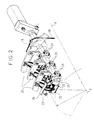
- the cable 18 is partially wound on pulleys, such as the pulley 19 shown in FIG. 2.
- Each of these pulleys is associated with one of the rows of supply brushes 20 that includes the engine at the slip rings 3 and each is rotatably mounted on a different brush holder shaft 21.
- a bent control rod 22 projects from each pulley 19 to come and extend along the assembly formed by the rings manifolds 3, parallel to the brush holder shaft 21 on which the considered pulley is mounted, so as to turn around this tree remaining parallel to it.
- the brushes 11 are conventionally arranged in lines parallel arranged with respect to the axis XX of the rotor and regularly distributed around the assembly formed by the rings collectors 3.
- Each brush 11 is housed in a brush-carrying element individual 23 from where it projects through a first end to be able to come into contact with a ring 3 of the rotor of which only the longitudinal axis XX is shown in Figure 2.
- Each brush 11 is also connected by a second end to one of the phase 24 supply crowns conductive and fixed which concentrically surround the assembly formed by slip rings 3.
- the brush holder elements 23 of the same line are carried by the same brush holder shaft 21 via individual flanges 25 on each of which is mounted a part metal intended to serve as a trigger, such as trigger 26 of the brush-holder element located opposite the pulley 19 on the shaft 21 in figure 2.
- each of the triggers which are fixed on the flanges 24 of a line of brush holder elements 22 of the same brush holder shaft 21 are arranged so as to simultaneously bear on the control rod 22 that comprises the pulley 19 mounted on this shaft, when it is driven to a position determined in rotation, after the rotation of the shaft 11 - see figure 1 - is caused the shorting of the bars 4 of the rotor by the short-circuiting crown.
- the invention therefore proposes a layout arrangement start-up means by motor rheostat asynchronous slip rings, the rotor of which has an element electrically insulated tubular on which rings are fixed conductive, which are parallel and centered on the axis of a central shaft of this rotor, which are electrically connected to busbars longitudinal connection of the winding with each ring and which are possibly connected to longitudinal busbars additional short-circuiting means, all these bars being spatially distributed evenly around the axis of the tree and projecting identically on the same side out of the set formed by the rings to cooperate with a shorting sub-assembly between rings, movable in translation along the axis of the shaft between a first position for which this subset, close to rings, ensures a short-circuiting of the rings by contact with the bars and a second position for which it is distant from rings and bars.
- the arrangement comprises a short-circuiting device where, on the one hand, each of the bars has a protruding ring shorting end which is provided with a contact member, of axial type, and where, on the other hand, electrically interconnected contact members, which are complementary to those which terminate the bars, are carried by a short-circuiting part, which positions these members complementary so that the contacts are made axially and frontally.
- the arrangement comprises a short-circuiting device where the contacts between contact and complementary contact bodies established axially and frontally, are ensured by penetration of one into the others, some being of the male type and the others of the female type.
- the arrangement comprises a short-circuiting device having contact members and complementary contact members which are of the type knife, the others of bimetal spring type.
- the arrangement comprises a short-circuiting device having contact members additional female type which are carried by the insert short-circuited, the male contacts being carried by the bars.
- the arrangement comprises a short-circuiting device having a short-circuiting part, socket type, sliding longitudinally over a portion rotor shaft under the thrust of the arms of a control fork which come to bear via mad rollers on one either of the U-shaped walls of a peripheral groove that the part comprises, this fork having its arms articulated each on an element fixed motor support and moving between two positions in function of the direction of rotation of a threaded motor shaft which cooperates with a threaded yoke integral with the part forming the handle of the fork.
- the invention also provides an arrangement for switching off starting means by rheostat for asynchronous motor with slip rings whose rotor has a tubular element electrically insulated on which conductive rings are fixed, which are parallel and centered on the axis of a central shaft of this rotor, these rings being designed to be supplied with electrical energy by through conductive brushes which are positioned on one or several fixed bearing trees angularly distributed so regular around the axis through individual brush holders thanks to which each of the brushes is pressed against the edge of one of the rings, each brush holder articulated with respect to the shaft carrying it being furthermore provided with a trigger-forming tab making it possible to angularly move the broom it carries from a first position to which this brush is resting on a ring at a second position for which it is discarded, this trigger being actuated by a lifting finger constituted by a control rod parallel to the shaft by which the brush holder in question is carried.
- the arrangement comprises a brush lifting device where each lifting finger, mounted rotatable around the shaft, is directly actuated by a movable core a fixed electromagnet, especially when lifting the brushes first in second position.
- the arrangement comprises a brush lifting device where the electromagnets, which act individually on the lifting fingers, have a circuit supply allowing simultaneous control of all.
- the arrangement comprises a brush lifting device with fixed electromagnets, the respective cores are each connected by a joint to a finger of lifting.
- the arrangement comprises a brush lifting device includes lifting fingers, each consisting of a rod carried by a radially projecting arm a rotating disc carried by the shaft on which the brushes intended to be raised by means of this rod, the triggers of these brushes being positioned on one side of this rod which is opposite to that where the joint on which a electromagnet core relative to the arm carrying this rod.
- the invention finally proposes an asynchronous motor with rings characterized in that it comprises a short-circuiting device and / or a device for lifting brushes having at least one of the characteristics mentioned above.
- Figure 1 shows a partial perspective diagram of a rotor of asynchronous ring motor fitted with a deactivation arrangement circuit of the starting means by rheostat and more particularly of the device for short-circuiting the busbars power supply to the rotor, as known.
- Figure 2 shows a partial perspective diagram of essential parts of the brush lifting device of the arrangement known mentioned above.
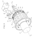
- Figure 3 shows a perspective diagram of one end rotor of asynchronous ring motor fitted with a device, according to the invention, for short-circuiting the busbars of food it contains.
- Figure 4 presents a diagram in perspective and in section partial of the interior of a rotor end fitted with the short circuit shown in Figure 3.
- Figure 5 shows a partial perspective diagram of a rotor end of asynchronous ring motor fitted with a device according to the invention for lifting the brushes.
- FIG. 6 presents a second partial diagram in perspective and in partial section of the interior of one end of an asynchronous motor rings fitted with the brush lifting device shown in Figure 5.
- the shutdown arrangement starting means by rheostat for asynchronous motor with rings which is proposed by the invention dissociates the means of setting bypass previously combined so as to allow maintain optimal engine operation over time by increasing reliability, in particular by simplifying the means put to improve the performance of the arrangement compared to to previous achievements by choosing the means for their effectiveness and their simplicity and to reduce the duration and the cost of the operations of maintenance.
- the arrangement according to the invention therefore comprises a device for short-circuiting the slip rings of an asynchronous motor with rings and a device for lifting brushes which are electrically successively ordered in a manner corresponding to that used implemented in the embodiments of the prior art, such as that mentioned above while being materially independent, as the shows the rest of the description.
- Rotor end of asynchronous ring motor shown in FIG. 1 comprises a cylindrical element 27 which is housed in an electrically insulated tubular member 28 which is analogous to the tubular element 1 shown in FIG. 1 and which comprises a crown 29 corresponding to the crown 2 of said figure 1 at one end.
- This tubular element 28 carries three conductive rings 30 for setting connection of the rotor winding, winding, not shown, which is located the other side of the crown 29 relative to the rings 30 arranged in parallel and centered on the axis XX of the rotor.
- Busbars longitudinal 31 ensure a selective connection of the different winding phases with the rings 30, as in the embodiment shown in Figures 1 and 2. For this purpose these bars 31 pass through the crown 29 without coming into contact with it. They protrude on the one hand on the other side of the crown 29 relative to the rings 30 to connect to the winding, for example in the same way as in the previous realization mentioned above, and on the other hand beyond ring 30 which is furthest from crown 29.
- Each of these bars 31 is electrically connected to a ring different for example by welding, as in the realization former.
- the spatial distribution of the bars 31 around the axis XX of the rotor is performed regularly to allow good balancing of the rotor, as necessary in this field.
- each of the bars 31 which project out of the assembly formed by the rings 30, beyond that of these rings which is furthest from the crown 29, is provided with a contact member 32, of axial type and for example a male contact of the knife type.
- This member is intended to cooperate with a contact member complementary 33, against which it comes to press here so as to penetrate, this complementary female type organ being for example a bimetal spring.
- These complementary contact bodies are here carried by a shorting part 34 which is here assumed constituted by a conductive sleeve centered on the axis XX of the rotor and mobile in translation along this axis.
- conductive bars additional longitudinal sections 35 come out beyond the ring 30 which is furthest from the crown 29, at same level as the bars 31, so as to constitute elements additional electrical conduction for short-circuiting.
- each of these additional bars 35 crosses all the rings 30, but not the crown 29 and is connected electrically by welding to one of these rings. Spatial distribution bars 31 and 35 around the rotor axis is made so regular to allow a good balance of the rotor, as necessary in this area.
- the ends of the additional bars 35 which project at the same level as those of the bars 31 beyond the ring 30 which is the further away from the crown 29 are provided with contact members 32 identical to those in the bars 31 so as to cooperate with complementary contact members 33 mounted on the workpiece short-circuiting 34, the number and arrangement of the additional contact 33 worn by this part corresponding to those contact members 32 carried by the bars 31 and 35.
- the displacement of the shorting part 34 according to the axis XX of the rotor shaft takes place between a first position, one corresponding to an axial contact of each of the complementary contact members 33 carried by the part with one of the contact members 32 carried by a busbar 31 or 35, and a second position where the additional contact members 33 are distant from the contact members 32 by a determined distance of way known to those skilled in the art not to allow the appearance or maintenance of electrical continuity between organs 32 and organs 33.
- each knife is inserted into the middle slit of the bimetallic strip facing it so that the portions elastic conductors of the bimetallic strip which border this slot come press on both sides of the conductive part serving as a blade for this knife.
- the additional contact members 33 which are made of a very good conductive material are electrically connected to each other by connecting elements 36, of bar type, carried by the piece of short-circuited 34 and themselves made of a very good material driver.
- the socket which constitutes the part of short-circuited 34 slides on a portion of central shaft with an axis XX of the rotor, not shown, under the action of a ordered.
- This mechanism is here assumed to be actuated by a servomotor 37 including a motor shaft 38 threaded at the end acts on a yoke 39 tapped accordingly.
- This yoke pulls or pushes the handle portion of a control fork 40, analogous to the fork 9, and this according to the direction of rotation selected for the servomotor 37.
- the fork has two arms which are respectively articulated each on a support element 41 which makes part of the fixed parts of the engine.
- each of the arms has a loose roller, not represented.
- the rollers are positioned in a groove peripheral serving as a raceway on the socket which here constitutes the short-circuiting part 34, according to an arrangement identical to that described in connection with the socket 6 and the fork 9 in the known embodiment mentioned above, this arrangement not being therefore neither repeated nor shown here.
- end stops are performed, according to a principle corresponding to that evoked with the previous embodiment described above, by a ball mounting subjected to the action of springs which is positioned in the part internal tubular that comprises the short-circuiting part 34 between this part and the portion of the rotor shaft on which it slides and in which are formed two circular grooves serving to block the movement of the part 24 at the end of the travel both in one direction than in the other.
- 1 has transmission of electrical energy to the rings 30 carried by the rotor of the asynchronous motor considered is ensured by conductive brushes 42 shown in FIG. 5 which are pressed against against the outer peripheral edge of the rings and which are connected each to one of the fixed supply conductive rings 43 which includes the motor.
- these crowns 43 are each associated with a ring 30 different from the rotor than practically it circles at a distance and the brushes are aligned in one or more generally several rows angularly distributed so regular around the axis XX with respect to which these rows are parallel.
- the supply rings 43 are here assumed to be mounted via insulating spacers 45 on a crown of support 44, for example of steel, which is here assumed to be fixed on a bottom disc 60 which is part of the fixed elements of the engine considered.
- Each row has a number of brushes 42 equal to the number rings 30, each row broom being powered by a crown 46 different he shares with other brooms who like him come rub around the same ring.
- each brush 42 is positioned at by means of an individual brush holder 47 relative to the ring against which he comes to rub.
- the brush holders 47 of a row of brushes 42 are here aligned on the same carrier shaft 48 on which they are mounted by by means of individual conductor fixing collars 49, each consisting for example of two complementary jaws bolted to each other which come to close and stop on the bearing shaft 48.
- each collar 49 is connected by a conductive lug 50 to one of the crowns 46, these lugs being sized and fixed to the crowns in a manner known per se for give determined positions to the collars on which they are respectively fixed.
- Each brush holder 47 is articulated on the collar which carries it and is arranged in a manner known to those skilled in the art to allow the broom 42 that it accommodates coming to bear against the outer edge of the ring 30 against which it is intended to rub, during the rotation of axis XX of the latter, this support being conventionally provided by means pressure by spring (s).
- An electrical connection is established between each broom and a crown via a lug conductor 47, a collar 49 and a not shown shunt which is electrically connected to the broom.
- Triggers 51 are associated with brush holders 47, they allow the brushes to be lifted so that they are no longer in contact with the rings on which they otherwise rely.
- each trigger 51 is associated with a different brush holder 47 and it is constituted by a rigid tab, here planned angled.
- This tab is fixed by a first end to the brush holder to which it is assigned and it includes a zone of control up to a second end on which it is provided to act to activate the trigger it forms.
- the triggers 51 relating to brush holders 47 mounted on a same bearing shaft 48 which are preferably identical, have their respective control zones arranged identically by example in parallel and in the same plane, at least when these triggers are not actuated.
- a rod, called lifting finger, 52 is associated with each row brush holders 47 mounted on the same carrier shaft 48. It is arranged so as to move while remaining parallel to this tree, being by example carried by a rotary disc 53 placed on the shaft considered above and for example mounted on needle bearing.
- This finger of lifting comes to press the triggers 51 associated with the brush holders 47 mounted on said shaft at the control zones of these triggers, when it goes from a first position to a second position for which it pushes back the brush holders by pressing on their triggers. In this latter position, the brushes 42 respectively housed in the brush holders 47 mounted on the same shaft are distant of the ring 30, against which they were previously supported, by the thrust of the lifting finger 52 which acts on the triggers 51 of these brush holder.
- each of the lifting fingers 52 is perpendicularly fixed on an arm 54 which projects from the disc which the door and which rotates around the axis of the shaft 48 carrying the row of brush holder 47 on which the finger acts.
- Electromagnets 55 are associated with the lifting fingers 52 whose movements they provide. These electromagnets 55 are by example fixed on the support ring 44 and each have a core 56 mobile in translation on electric control.
- each nucleus acts on a lifting finger 52 to which it is connected by a joint 57, and therefore allows this finger to pass from one to the other of these positions.
- Electric control by electromagnets directly on the lifting fingers provides rapid and precise actuation, particularly advantageous in terms of wear of the brushes, which was not likely to be obtained with the previous embodiment mentioned in the preamble to this application.
- the number of components of the lifting device is reduced, which favors reliability and these elements are easily standardized, which simplifies assembly operations and of maintenance.
Landscapes
- Engineering & Computer Science (AREA)
- Power Engineering (AREA)
- Motor Or Generator Current Collectors (AREA)
- Control Of Direct Current Motors (AREA)
- Control Of Electric Motors In General (AREA)
- Motor And Converter Starters (AREA)
- Control Of Ac Motors In General (AREA)
- Rotational Drive Of Disk (AREA)
- Connection Of Motors, Electrical Generators, Mechanical Devices, And The Like (AREA)
- Adjustable Resistors (AREA)
- Harvester Elements (AREA)
- Pharmaceuticals Containing Other Organic And Inorganic Compounds (AREA)
- Valve-Gear Or Valve Arrangements (AREA)
- Paper (AREA)
- Dc Machiner (AREA)
Applications Claiming Priority (2)
| Application Number | Priority Date | Filing Date | Title |
|---|---|---|---|
| FR9701344 | 1997-02-06 | ||
| FR9701344A FR2759215B1 (fr) | 1997-02-06 | 1997-02-06 | Agencement de mise hors-circuit des moyens de demarrage par rheostat pour moteur asynchrone a bagues et moteur equipe d'un tel agencement |
Publications (2)
| Publication Number | Publication Date |
|---|---|
| EP0858148A1 true EP0858148A1 (de) | 1998-08-12 |
| EP0858148B1 EP0858148B1 (de) | 2005-04-20 |
Family
ID=9503392
Family Applications (1)
| Application Number | Title | Priority Date | Filing Date |
|---|---|---|---|
| EP98400248A Expired - Lifetime EP0858148B1 (de) | 1997-02-06 | 1998-02-05 | Anordnung zur Abschaltung der Rheostat Andrehvorrichtung einer Schleifring-Asynchronmaschine, und Motor mit dieser Anordnung |
Country Status (9)
| Country | Link |
|---|---|
| EP (1) | EP0858148B1 (de) |
| AT (1) | ATE293847T1 (de) |
| DE (1) | DE69829791T2 (de) |
| DK (1) | DK0858148T3 (de) |
| ES (1) | ES2242264T3 (de) |
| FR (1) | FR2759215B1 (de) |
| NO (1) | NO319748B1 (de) |
| PT (1) | PT858148E (de) |
| ZA (1) | ZA98976B (de) |
Cited By (7)
| Publication number | Priority date | Publication date | Assignee | Title |
|---|---|---|---|---|
| DE10003900A1 (de) * | 2000-01-29 | 2002-05-02 | Schunk Metall & Kunststoff | Stromübertragungsanordnung |
| US6700267B2 (en) | 2001-03-01 | 2004-03-02 | Deere & Company | Transverse flux drive |
| WO2010121983A1 (de) * | 2009-04-24 | 2010-10-28 | Alstom Technology Ltd. | Elektrische maschine mit einer rotorwicklung, die über schleifringe mit strom versorgt wird |
| WO2011110429A2 (de) | 2010-03-10 | 2011-09-15 | Ssb Wind Systems Gmbh & Co. Kg | Redundantes pitchsystem |
| EP3404811A1 (de) * | 2017-05-15 | 2018-11-21 | ABB Schweiz AG | Schleifringkörper für einen gewickelten läufermotor |
| CN111355346A (zh) * | 2015-04-17 | 2020-06-30 | 西门子公司 | 用于电激励的旋转机电发电机的转子的滑环体 |
| EP3975351A4 (de) * | 2019-05-22 | 2023-04-19 | Weg Equipamentos Electricos S.A. | Höhenverstellbares bürstenhaltersystem für statischen betrieb und entsprechende elektrische drehmaschine |
Families Citing this family (3)
| Publication number | Priority date | Publication date | Assignee | Title |
|---|---|---|---|---|
| US10566886B2 (en) * | 2015-12-03 | 2020-02-18 | Linde Aktiengesellschaft | Female contact element for a slip ring motor and slip ring motor |
| EP3754796A1 (de) * | 2019-06-18 | 2020-12-23 | MERSEN Osterreich Hittisau Ges.m.b.H | Bürstenhalter und stützstabvorrichtung die zusammenpassen |
| DE102022102602A1 (de) | 2022-02-03 | 2023-08-03 | Audi Aktiengesellschaft | Fremderregte Elektromaschine |
Citations (3)
| Publication number | Priority date | Publication date | Assignee | Title |
|---|---|---|---|---|
| GB109087A (en) * | 1916-08-29 | 1917-08-29 | Giuseppe Pestarini | Improvements relating to Induction Electric Motors. |
| DE2510431A1 (de) * | 1975-03-11 | 1976-09-16 | Kirsch Kg Bernhard | Elektrische maschine mit auf ihrer welle angeordneten schleifringkoerpern, kollektoren oder dergleichen und schleifkontakten |
| WO1991015050A1 (de) * | 1990-03-23 | 1991-10-03 | Siemens Aktiengesellschaft | Kurzschluss- und bürstenabhebevorrichtung für asynchronmotoren mit schleifringlaüfer |
-
1997
- 1997-02-06 FR FR9701344A patent/FR2759215B1/fr not_active Expired - Lifetime
-
1998
- 1998-02-05 EP EP98400248A patent/EP0858148B1/de not_active Expired - Lifetime
- 1998-02-05 DK DK98400248T patent/DK0858148T3/da active
- 1998-02-05 DE DE69829791T patent/DE69829791T2/de not_active Expired - Lifetime
- 1998-02-05 AT AT98400248T patent/ATE293847T1/de not_active IP Right Cessation
- 1998-02-05 NO NO19980502A patent/NO319748B1/no unknown
- 1998-02-05 PT PT98400248T patent/PT858148E/pt unknown
- 1998-02-05 ES ES98400248T patent/ES2242264T3/es not_active Expired - Lifetime
- 1998-02-06 ZA ZA98976A patent/ZA98976B/xx unknown
Patent Citations (3)
| Publication number | Priority date | Publication date | Assignee | Title |
|---|---|---|---|---|
| GB109087A (en) * | 1916-08-29 | 1917-08-29 | Giuseppe Pestarini | Improvements relating to Induction Electric Motors. |
| DE2510431A1 (de) * | 1975-03-11 | 1976-09-16 | Kirsch Kg Bernhard | Elektrische maschine mit auf ihrer welle angeordneten schleifringkoerpern, kollektoren oder dergleichen und schleifkontakten |
| WO1991015050A1 (de) * | 1990-03-23 | 1991-10-03 | Siemens Aktiengesellschaft | Kurzschluss- und bürstenabhebevorrichtung für asynchronmotoren mit schleifringlaüfer |
Cited By (15)
| Publication number | Priority date | Publication date | Assignee | Title |
|---|---|---|---|---|
| DE10003900A1 (de) * | 2000-01-29 | 2002-05-02 | Schunk Metall & Kunststoff | Stromübertragungsanordnung |
| DE10003900B4 (de) * | 2000-01-29 | 2004-02-19 | Schunk Metall Und Kunststoff Gmbh | Stromübertragungsanordnung |
| US6700267B2 (en) | 2001-03-01 | 2004-03-02 | Deere & Company | Transverse flux drive |
| WO2010121983A1 (de) * | 2009-04-24 | 2010-10-28 | Alstom Technology Ltd. | Elektrische maschine mit einer rotorwicklung, die über schleifringe mit strom versorgt wird |
| WO2011110429A3 (de) * | 2010-03-10 | 2012-06-21 | Ssb Wind Systems Gmbh & Co. Kg | Redundantes pitchsystem |
| CN102192085A (zh) * | 2010-03-10 | 2011-09-21 | Ssb风系统两合公司 | 冗余的变桨系统 |
| WO2011110429A2 (de) | 2010-03-10 | 2011-09-15 | Ssb Wind Systems Gmbh & Co. Kg | Redundantes pitchsystem |
| CN102192085B (zh) * | 2010-03-10 | 2014-01-29 | Ssb风系统两合公司 | 冗余的变桨系统 |
| KR101487697B1 (ko) * | 2010-03-10 | 2015-01-29 | 에스에스비 윈드 시스템즈 게엠베하 운트 코 카게 | 여분성 피치 시스템 |
| US9422919B2 (en) | 2010-03-10 | 2016-08-23 | Ssb Wind Systems Gmbh & Co. Kg | Redundant pitch system |
| CN111355346A (zh) * | 2015-04-17 | 2020-06-30 | 西门子公司 | 用于电激励的旋转机电发电机的转子的滑环体 |
| EP3404811A1 (de) * | 2017-05-15 | 2018-11-21 | ABB Schweiz AG | Schleifringkörper für einen gewickelten läufermotor |
| CN108880128A (zh) * | 2017-05-15 | 2018-11-23 | Abb瑞士股份有限公司 | 用于绕线式转子电动机的滑环单元 |
| CN108880128B (zh) * | 2017-05-15 | 2021-07-13 | Abb瑞士股份有限公司 | 用于绕线式转子电动机的滑环单元 |
| EP3975351A4 (de) * | 2019-05-22 | 2023-04-19 | Weg Equipamentos Electricos S.A. | Höhenverstellbares bürstenhaltersystem für statischen betrieb und entsprechende elektrische drehmaschine |
Also Published As
| Publication number | Publication date |
|---|---|
| ZA98976B (en) | 1998-08-17 |
| FR2759215A1 (fr) | 1998-08-07 |
| DE69829791D1 (de) | 2005-05-25 |
| NO980502D0 (no) | 1998-02-05 |
| DE69829791T2 (de) | 2006-03-09 |
| NO319748B1 (no) | 2005-09-12 |
| FR2759215B1 (fr) | 1999-04-02 |
| NO980502L (no) | 1998-08-07 |
| ATE293847T1 (de) | 2005-05-15 |
| EP0858148B1 (de) | 2005-04-20 |
| DK0858148T3 (da) | 2005-08-15 |
| PT858148E (pt) | 2005-08-31 |
| ES2242264T3 (es) | 2005-11-01 |
Similar Documents
| Publication | Publication Date | Title |
|---|---|---|
| EP1554794B1 (de) | Anordnung zum schweissen von leitersegmenten der wicklung einer rotierenden elektrischen maschine | |
| EP0858148B1 (de) | Anordnung zur Abschaltung der Rheostat Andrehvorrichtung einer Schleifring-Asynchronmaschine, und Motor mit dieser Anordnung | |
| EP0087372A1 (de) | Hochfrequenzumschaltrelais mit Koaxialkontakten | |
| FR2553571A1 (fr) | Interrupteur a contact instantane notamment pour l'equipement des vehicules automobiles | |
| WO2004001931A1 (fr) | Dispositif de prehension et de transfert d’une couronne de conducteurs electriques, destinee a la realisation d’un bobinage, et system de realisation d’un bobinage utilisant un tel dispositif | |
| FR2530885A1 (fr) | Sous-ensemble d'alimentation pour moteur electrique, et moteur comprenant un tel sous-ensemble | |
| EP0149940B1 (de) | Elektrische Lage-Steueranlage einer sich öffnenden Schiebefläche eines Kraftfahrzeuges | |
| EP0569651B1 (de) | Montageverfahren für Phasen-Neutralleiter-Schutzschalter und Schutzschalter dieser Bauart | |
| EP1289390B1 (de) | Epilationsapparat mit pinzetten | |
| EP3610562B1 (de) | Elektrischer synchronmotor und verfahren zur montage des besagten elektrischen motors | |
| BE509072A (de) | ||
| EP0891627A1 (de) | Modulare elektrische schalteranordung | |
| FR2890780A1 (fr) | Contacteur de demarreur de moteur thermique comportant des moyens perfectionnes de raccordement electrique de son bobinage | |
| EP3231067B1 (de) | Verbesserter bürstenkäfig für kraftfahrzeuganlasser und zugehöriger bürstenhalter, elektromotor und kraftfahrzeuganlasser | |
| EP1020966A1 (de) | System zum einbringen von stiften in vorrichtungen wie zum biespiel einen verbinder | |
| EP1843434A1 (de) | Steckdose mit kontrollierter Steck- und Ausziehkraft | |
| FR2576141A1 (fr) | Disjoncteur basse tension, avec verrou de maintien agence dans une chambre separee | |
| EP0220093B1 (de) | Anzeigevorrichtung mit Vorwahl für Programmierer | |
| WO1987006396A1 (fr) | Dispositif de contact electrique a balai pour moteur electrique a commutateur cylindrique | |
| EP0518768B1 (de) | Schaltgerät für die Programmschalteinrichtung eines elektrischen Haushaltgerät | |
| EP3762955B1 (de) | Synchronisierte bewegung einer bistabilen vorrichtung aus einer vielzahl monostabiler hebel | |
| FR2642865A1 (fr) | Programmateur a dispositif d'affichage a preselection | |
| WO2013083646A1 (fr) | Dispositif électrique d'entraînement en translation d'une pièce, appareil de commutation électrique comportant un tel dispositif et inverseur triphasé comprenant un tel appareil | |
| FR2928045A1 (fr) | Dispositif a balai destine a assurer une liaison electrique avec un collecteur dans une machine electrique tournante | |
| FR2604292A1 (fr) | Perfectionnements aux commutateurs electriques, en particulier pour la commande de lave-essuie glace de vehicules automobiles |
Legal Events
| Date | Code | Title | Description |
|---|---|---|---|
| PUAI | Public reference made under article 153(3) epc to a published international application that has entered the european phase |
Free format text: ORIGINAL CODE: 0009012 |
|
| AK | Designated contracting states |
Kind code of ref document: A1 Designated state(s): AT BE CH DE DK ES FI GB GR IE IT LI LU MC NL PT SE |
|
| AX | Request for extension of the european patent |
Free format text: AL;LT;LV;MK;RO;SI |
|
| AKX | Designation fees paid |
Free format text: AT BE CH DE DK ES FI GB GR IE IT LI LU MC NL PT SE |
|
| RBV | Designated contracting states (corrected) |
Designated state(s): AT BE CH DE DK ES FI GB GR IE IT LI LU MC NL PT SE |
|
| 17P | Request for examination filed |
Effective date: 19990408 |
|
| GRAP | Despatch of communication of intention to grant a patent |
Free format text: ORIGINAL CODE: EPIDOSNIGR1 |
|
| GRAS | Grant fee paid |
Free format text: ORIGINAL CODE: EPIDOSNIGR3 |
|
| GRAA | (expected) grant |
Free format text: ORIGINAL CODE: 0009210 |
|
| AK | Designated contracting states |
Kind code of ref document: B1 Designated state(s): AT BE CH DE DK ES FI GB GR IE IT LI LU MC NL PT SE |
|
| PG25 | Lapsed in a contracting state [announced via postgrant information from national office to epo] |
Ref country code: NL Free format text: LAPSE BECAUSE OF FAILURE TO SUBMIT A TRANSLATION OF THE DESCRIPTION OR TO PAY THE FEE WITHIN THE PRESCRIBED TIME-LIMIT Effective date: 20050420 Ref country code: IE Free format text: LAPSE BECAUSE OF FAILURE TO SUBMIT A TRANSLATION OF THE DESCRIPTION OR TO PAY THE FEE WITHIN THE PRESCRIBED TIME-LIMIT Effective date: 20050420 |
|
| REG | Reference to a national code |
Ref country code: GB Ref legal event code: FG4D Free format text: NOT ENGLISH |
|
| REG | Reference to a national code |
Ref country code: CH Ref legal event code: EP |
|
| REG | Reference to a national code |
Ref country code: IE Ref legal event code: FG4D Free format text: LANGUAGE OF EP DOCUMENT: FRENCH |
|
| REF | Corresponds to: |
Ref document number: 69829791 Country of ref document: DE Date of ref document: 20050525 Kind code of ref document: P |
|
| PG25 | Lapsed in a contracting state [announced via postgrant information from national office to epo] |
Ref country code: GR Free format text: LAPSE BECAUSE OF FAILURE TO SUBMIT A TRANSLATION OF THE DESCRIPTION OR TO PAY THE FEE WITHIN THE PRESCRIBED TIME-LIMIT Effective date: 20050720 |
|
| REG | Reference to a national code |
Ref country code: SE Ref legal event code: TRGR |
|
| REG | Reference to a national code |
Ref country code: DK Ref legal event code: T3 |
|
| GBT | Gb: translation of ep patent filed (gb section 77(6)(a)/1977) |
Effective date: 20050725 |
|
| REG | Reference to a national code |
Ref country code: PT Ref legal event code: SC4A Effective date: 20050707 |
|
| NLV1 | Nl: lapsed or annulled due to failure to fulfill the requirements of art. 29p and 29m of the patents act | ||
| REG | Reference to a national code |
Ref country code: ES Ref legal event code: FG2A Ref document number: 2242264 Country of ref document: ES Kind code of ref document: T3 |
|
| REG | Reference to a national code |
Ref country code: IE Ref legal event code: FD4D |
|
| PLBE | No opposition filed within time limit |
Free format text: ORIGINAL CODE: 0009261 |
|
| STAA | Information on the status of an ep patent application or granted ep patent |
Free format text: STATUS: NO OPPOSITION FILED WITHIN TIME LIMIT |
|
| PG25 | Lapsed in a contracting state [announced via postgrant information from national office to epo] |
Ref country code: BE Free format text: LAPSE BECAUSE OF NON-PAYMENT OF DUE FEES Effective date: 20060228 |
|
| 26N | No opposition filed |
Effective date: 20060123 |
|
| PGFP | Annual fee paid to national office [announced via postgrant information from national office to epo] |
Ref country code: AT Payment date: 20070118 Year of fee payment: 10 |
|
| PGFP | Annual fee paid to national office [announced via postgrant information from national office to epo] |
Ref country code: MC Payment date: 20070122 Year of fee payment: 10 |
|
| PGFP | Annual fee paid to national office [announced via postgrant information from national office to epo] |
Ref country code: DK Payment date: 20070123 Year of fee payment: 10 |
|
| PGFP | Annual fee paid to national office [announced via postgrant information from national office to epo] |
Ref country code: PT Payment date: 20070129 Year of fee payment: 10 |
|
| PGFP | Annual fee paid to national office [announced via postgrant information from national office to epo] |
Ref country code: GB Payment date: 20070209 Year of fee payment: 10 |
|
| PGFP | Annual fee paid to national office [announced via postgrant information from national office to epo] |
Ref country code: LU Payment date: 20070418 Year of fee payment: 10 |
|
| BERE | Be: lapsed |
Owner name: GEC ALSTHOM MOTEURS SA Effective date: 20060228 |
|
| REG | Reference to a national code |
Ref country code: PT Ref legal event code: MM4A Free format text: LAPSE DUE TO NON-PAYMENT OF FEES Effective date: 20080805 |
|
| REG | Reference to a national code |
Ref country code: DK Ref legal event code: EBP |
|
| GBPC | Gb: european patent ceased through non-payment of renewal fee |
Effective date: 20080205 |
|
| PG25 | Lapsed in a contracting state [announced via postgrant information from national office to epo] |
Ref country code: PT Free format text: LAPSE BECAUSE OF NON-PAYMENT OF DUE FEES Effective date: 20080805 Ref country code: MC Free format text: LAPSE BECAUSE OF NON-PAYMENT OF DUE FEES Effective date: 20080228 |
|
| PG25 | Lapsed in a contracting state [announced via postgrant information from national office to epo] |
Ref country code: AT Free format text: LAPSE BECAUSE OF NON-PAYMENT OF DUE FEES Effective date: 20080205 |
|
| PG25 | Lapsed in a contracting state [announced via postgrant information from national office to epo] |
Ref country code: DK Free format text: LAPSE BECAUSE OF NON-PAYMENT OF DUE FEES Effective date: 20080229 |
|
| PGFP | Annual fee paid to national office [announced via postgrant information from national office to epo] |
Ref country code: ES Payment date: 20090220 Year of fee payment: 12 |
|
| PG25 | Lapsed in a contracting state [announced via postgrant information from national office to epo] |
Ref country code: GB Free format text: LAPSE BECAUSE OF NON-PAYMENT OF DUE FEES Effective date: 20080205 |
|
| PG25 | Lapsed in a contracting state [announced via postgrant information from national office to epo] |
Ref country code: LU Free format text: LAPSE BECAUSE OF NON-PAYMENT OF DUE FEES Effective date: 20080205 |
|
| REG | Reference to a national code |
Ref country code: ES Ref legal event code: FD2A Effective date: 20110404 |
|
| PG25 | Lapsed in a contracting state [announced via postgrant information from national office to epo] |
Ref country code: ES Free format text: LAPSE BECAUSE OF NON-PAYMENT OF DUE FEES Effective date: 20110322 |
|
| PG25 | Lapsed in a contracting state [announced via postgrant information from national office to epo] |
Ref country code: ES Free format text: LAPSE BECAUSE OF NON-PAYMENT OF DUE FEES Effective date: 20100206 |
|
| REG | Reference to a national code |
Ref country code: DE Ref legal event code: R082 Ref document number: 69829791 Country of ref document: DE Representative=s name: RUEGER, BARTHELT & ABEL PATENTANWAELTE, DE |
|
| PGFP | Annual fee paid to national office [announced via postgrant information from national office to epo] |
Ref country code: FI Payment date: 20150226 Year of fee payment: 18 Ref country code: IT Payment date: 20150225 Year of fee payment: 18 Ref country code: CH Payment date: 20150226 Year of fee payment: 18 |
|
| PGFP | Annual fee paid to national office [announced via postgrant information from national office to epo] |
Ref country code: SE Payment date: 20150226 Year of fee payment: 18 |
|
| REG | Reference to a national code |
Ref country code: CH Ref legal event code: PL |
|
| REG | Reference to a national code |
Ref country code: SE Ref legal event code: EUG |
|
| PG25 | Lapsed in a contracting state [announced via postgrant information from national office to epo] |
Ref country code: CH Free format text: LAPSE BECAUSE OF NON-PAYMENT OF DUE FEES Effective date: 20160229 Ref country code: FI Free format text: LAPSE BECAUSE OF NON-PAYMENT OF DUE FEES Effective date: 20160205 Ref country code: LI Free format text: LAPSE BECAUSE OF NON-PAYMENT OF DUE FEES Effective date: 20160229 |
|
| PG25 | Lapsed in a contracting state [announced via postgrant information from national office to epo] |
Ref country code: SE Free format text: LAPSE BECAUSE OF NON-PAYMENT OF DUE FEES Effective date: 20160206 |
|
| PG25 | Lapsed in a contracting state [announced via postgrant information from national office to epo] |
Ref country code: IT Free format text: LAPSE BECAUSE OF NON-PAYMENT OF DUE FEES Effective date: 20160205 |
|
| PGFP | Annual fee paid to national office [announced via postgrant information from national office to epo] |
Ref country code: DE Payment date: 20170227 Year of fee payment: 20 |
|
| REG | Reference to a national code |
Ref country code: DE Ref legal event code: R071 Ref document number: 69829791 Country of ref document: DE |