EP0858166B1 - Clavier étanche et appareil de cuisson comportant un tel clavier - Google Patents
Clavier étanche et appareil de cuisson comportant un tel clavier Download PDFInfo
- Publication number
- EP0858166B1 EP0858166B1 EP19970400274 EP97400274A EP0858166B1 EP 0858166 B1 EP0858166 B1 EP 0858166B1 EP 19970400274 EP19970400274 EP 19970400274 EP 97400274 A EP97400274 A EP 97400274A EP 0858166 B1 EP0858166 B1 EP 0858166B1
- Authority
- EP
- European Patent Office
- Prior art keywords
- printed circuit
- keyboard
- tracks
- keyboard according
- receiving
- Prior art date
- Legal status (The legal status is an assumption and is not a legal conclusion. Google has not performed a legal analysis and makes no representation as to the accuracy of the status listed.)
- Expired - Lifetime
Links
Images

Classifications
-
- H—ELECTRICITY
- H03—ELECTRONIC CIRCUITRY
- H03K—PULSE TECHNIQUE
- H03K17/00—Electronic switching or gating, i.e. not by contact-making and –breaking
- H03K17/94—Electronic switching or gating, i.e. not by contact-making and –breaking characterised by the way in which the control signals are generated
- H03K17/96—Touch switches
- H03K17/962—Capacitive touch switches
- H03K17/9622—Capacitive touch switches using a plurality of detectors, e.g. keyboard
-
- H—ELECTRICITY
- H03—ELECTRONIC CIRCUITRY
- H03K—PULSE TECHNIQUE
- H03K17/00—Electronic switching or gating, i.e. not by contact-making and –breaking
- H03K17/94—Electronic switching or gating, i.e. not by contact-making and –breaking characterised by the way in which the control signals are generated
- H03K17/96—Touch switches
- H03K2017/9602—Touch switches characterised by the type or shape of the sensing electrodes
-
- H—ELECTRICITY
- H03—ELECTRONIC CIRCUITRY
- H03K—PULSE TECHNIQUE
- H03K2217/00—Indexing scheme related to electronic switching or gating, i.e. not by contact-making or -breaking covered by H03K17/00
- H03K2217/94—Indexing scheme related to electronic switching or gating, i.e. not by contact-making or -breaking covered by H03K17/00 characterised by the way in which the control signal is generated
- H03K2217/96—Touch switches
- H03K2217/96015—Constructional details for touch switches
- H03K2217/96023—Details of electro-mechanic connections between different elements, e.g.: sensing plate and integrated circuit containing electronics
-
- H—ELECTRICITY
- H03—ELECTRONIC CIRCUITRY
- H03K—PULSE TECHNIQUE
- H03K2217/00—Indexing scheme related to electronic switching or gating, i.e. not by contact-making or -breaking covered by H03K17/00
- H03K2217/94—Indexing scheme related to electronic switching or gating, i.e. not by contact-making or -breaking covered by H03K17/00 characterised by the way in which the control signal is generated
- H03K2217/96—Touch switches
- H03K2217/9607—Capacitive touch switches
- H03K2217/960755—Constructional details of capacitive touch and proximity switches
- H03K2217/96076—Constructional details of capacitive touch and proximity switches with spring electrode
Definitions
- the present invention relates to a keyboard, preferably waterproof, and to appliances, in particular for cooking, comprising such a keyboard.
- Household or industrial appliances are frequently controlled by watertight keyboards to avoid attack by harsh environment or to protect the environment against the risk of explosion or pollution resulting from the operation of the keyboard.
- EP-A-0 603 039 describes a waterproof keyboard, each key of which includes a high frequency radio frequency emitter connected to a transmit antenna, as well as a receive antenna connected to a receiver, the signals transmitted between the transmitting antennas and reception being attenuated by the presence of an operator's finger at the right of the button.
- the transmitting antenna for each button is screen printed on a first face of a printed circuit, the receiving antenna being screen printed opposite on the opposite side of this circuit.
- the printed circuit double-sided was placed near a sealing wall, in particular a ceramic hob.
- this keyboard has drawbacks. Its sensitivity varies with the distance between the sealing wall and printed circuit. High precision in mounting the circuit board on the chassis of a device, significantly increasing the cost of the device, is necessary to maintain a distance between the printed circuit and the sealing wall and so that all keyboards produced and all keys on each keyboard have the same sensitivity.
- a keyboard according to the preamble of claim 1 is known from document FR-A-2 704 332.
- a keyboard comprising a printed circuit provided with a transmitting antenna connected to a high frequency generator or to a radio frequency generator and a receiving antenna connected to a detection circuit.
- At least one said antennas, advantageously the receiving antenna is connected to a projecting element, preferably elastic, disposed substantially perpendicular to the printed circuit to be applied on one side internal of a sealing wall to the right of the detection location of the presence of a finger on a key on the keyboard.
- the transmitting and receiving antennas are arranged on the same face of the printed circuit.
- the main object of the invention is a keyboard, in particular waterproof, comprising at least one key comprising a projecting element conductor extending to the proximity of a finger receiving area pressing the key, characterized in that it further comprises a transmitting antenna connected to a high frequency generator or to a radio frequency generator and a receiving antenna connected to a receiver, said antennas comprising tracks of a printed circuit and that said projecting element is connected to one of said antennas.
- the invention also relates to a keyboard, characterized in that the protruding element is connected to the receiving antenna.
- the invention also relates to a keyboard, characterized in that the protruding member has a spring extending substantially perpendicular to the printed circuit.
- the invention also relates to a keyboard, characterized in what the tracks of the printed circuit of the transmitting antenna and the tracks of the PCB of the receiving antenna are on the same side of said printed circuit board.
- the invention also relates to a keyboard, characterized in what the printed circuit is a single layer circuit.
- the invention also relates to a keyboard, characterized in what the tracks of the printed circuit of the transmitting antenna surround substantially the tracks of the printed circuit of the receiving antenna.
- the invention also relates to a keyboard, characterized in what it includes display means, in particular with diode electroluminescent, secured to the printed circuit.
- the invention also relates to a household appliance, characterized in that it comprises a control keyboard according to the invention.
- the invention also relates to a household appliance, characterized in that said appliance is a ceramic hob and in that the conductive projecting elements extend to the areas of the internal face of a ceramic hob facing the areas of reception of a finger pressing the corresponding key.
- FIGS. 1 to 6 the same references have been used for designate the same elements.
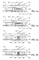
- a printed circuit 1 arranged behind a sealing wall 3, in particular a ceramic glass plate of a domestic cooking appliance, bearing, on a first main face 5, a transmitting antenna 7 and, on an opposite face 9 of the printed circuit 1, a receiving antenna 11 forming a key on a waterproof keyboard to detect the presence of a finger 13.
- the construction of a keyboard sensitive requires that the distance d between the face 9 of the printed circuit 1 and a face 15 of the sealing wall 3 disposed opposite, or weak, preventing the mounting on the printed circuit 1 of the display devices 17 to light emitting diode mounted in standard boxes.
- a second circuit printed 16 carries the display device 17 as well as the printed circuit 1 mounted on spacers 21, for example on pads making it possible to bring the receiving antenna 11 closer to the sealing wall 3.
- the second printed circuit 16 is usually mounted on the chassis (not shown) of the cooking appliance.
- the imprecision of the assembly does not allow maintain a constant distance D between the printed circuit 16 and the wall seal 3 and consequently the distance d between the face 9 of the printed circuit 1 and the face 15 of the sealing wall 3.
- each keyboard has a different sensitivity or even that the sensitivity of the various keys of a same keyboard is not always constant.
- the distances D and d are greater than those of the example illustrated in Figure 1b.
- the preferred embodiment of the keyboard according to the present invention comprising a single printed circuit 23 arranged parallel to a sealing wall 3, for example to a plate glass-ceramic cooker.
- the antenna reception 29 is connected, for example, through a hole metallized not shown, with a conducting and elastic projecting element 31 disposed between a second main face 33 of the circuit 23 and the face 15 of the sealing wall 3.
- the projecting element 31 extends substantially normally on the plane of the printed circuit 23.
- the elasticity of the antenna protruding element 31 makes it possible to apply one of its ends 35 on the face 15 of the sealing wall 3 regardless of the distance D ' separating the printed circuit 23 from said face 15 and thus makes it possible to compensate possible inaccuracies in mounting the printed circuit 23 on a possible frame.
- the sensitivity of the keyboard of FIG. 2a for which the distance D 'is relatively large is equal to that of the keyboard illustrated in Figure 2b for which this distance D 'is smaller.
- this distance is sufficient to allow the device to be installed display 17 on circuit 23, which avoids the use of multiple circuits and reduces the cost price.
- the present invention is not limited to the use of metal springs, in particular of iron or alloy of iron, as salient elements 31.
- metal springs in particular of iron or alloy of iron
- conductive tapes such as elastic metallic ribbons or tracks conductive of a flexible printed circuit.
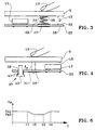
- the present invention is not limited to the implementation work of circuits 23 single faces but on the contrary extends to circuits multilayer or double-sided circuit, an example of which is illustrated on the Figure 3.
- the transmitting antenna 27 is disposed on the face 25 of the printed circuit 23 while the receiving antenna 29 is arranged on the face 33 of the printed circuit 23 located opposite the face 15 of the sealing wall 3.
- the elastic conducting protruding element 31 is connected to the antenna 29, for example by welding. This solder can also secure it to the printed circuit 23.
- the solidarity is ensured by other means (not shown), such as example by gluing or clipping.
- the printed circuit 23 is mounted floating on a support 37.
- the reception antenna 29 is connected to a rigid conductive projecting element 31 'extending in direction of the face 15 of the sealing wall 3.
- the height of the elements protruding conductors 31 ' provides sufficient space on the printed circuit 23 for mounting the display devices 17.
- the means 37 include studs cylindrical with axes orthogonal to the printed circuit 23 and to the wall seal 3 passing through openings 39 in the circuit printed 23.
- Each button has a transmitting antenna 27 connected to a generator radio frequency 45, for example to a square wave generator or sine waves whose voltage varies between 0 and 24 V, at a frequency included between 100 kHz and 300 kHz, preferably between 140 kHz and 220 kHz, by example a frequency substantially equal to 200 kHz.
- a generator radio frequency 45 for example to a square wave generator or sine waves whose voltage varies between 0 and 24 V, at a frequency included between 100 kHz and 300 kHz, preferably between 140 kHz and 220 kHz, by example a frequency substantially equal to 200 kHz.
- Each transmitting antenna 27 is associated with an antenna reception 29 connected to a receiver 47.
- the transmitting antenna 27 has a substantially rectangular shape comprising a discontinuity 48 in the passage of the connection of the antenna reception 29 at receiver 47.
- the reception antenna 29 has, for example, the shape of a square or rectangular spiral with cut angles.
- Antennas 27 transmission and 29 reception can of course have different configurations, such as a circular spiral.
- Entrance of the receiver 47 is connected to its output by a resistor 49, for example of 22 k ⁇ .
- Ground 51 is connected to the input of the receiver by a diode 53, by example of type 1N 4 1, 4 8.
- Earth 51 is connected to the output of the receiver 47, in parallel by a capacitor 55, for example of 100 nF and by a resistor 57, for example 220 k ⁇ .
- a voltage Vs characteristic of the state of the keyboard key corresponding.
- the keyboard of FIG. 5 comprises a circuit monolayer print, further provided with elements 31 and devices display 17 (not shown) in FIG. 5.
- the voltage Vs drops from Vs1 to a value Vs2, for example equal to 1 V. Between t2 and t3, the voltage Vs is a constant equal at Vs2. Between t3 and t4, the voltage rises from Vs2 to Vs1.
- t2 - t1 is for example between 1 ms and 5 ms, and t4 - t3 is for example between 4 ms and 5 ms.
- the present invention is not limited to the printed circuit 23 plan but also extends to the printed circuit shaped to a not necessarily flat wall of a product or directly printed on the internal face of an insulating wall of a product as well as using flexible circuits.
- the present invention is not limited to the implementation of conductive projecting elements 31 but extends also to any single-layer printed circuit comprising, for each keyboard key, on the same side of the circuit, a transmitting antenna and the corresponding receiving antenna.
- the present invention applies in particular to the production waterproof keypads for harsh environments and for devices domestic workers.
- the present invention applies mainly to keyboards for controlling hobs with a ceramic hob.
Landscapes
- Input From Keyboards Or The Like (AREA)
- Push-Button Switches (AREA)
Description
- la figure 1 comporte deux vues en coupe d'un dispositif de type connu ;
- la figure 2 comporte deux vues en coupe de l'exemple préféré de réalisation du dispositif selon la présente invention ;
- la figure 3 est une vue en coupe d'une variante de réalisation du dispositif selon la présente invention ;
- la figure 4 est une vue en coupe d'une autre variante du dispositif selon l'invention ;
- la figure 5 est un schéma électrique de l'exemple préféré de réalisation du dispositif selon la présente invention ;
- la figure 6 est une courbe illustrant la variation de la tension de sortie du dispositif de la figure 4 en fonction du temps.
Claims (9)
- Clavier, notamment étanche, comportant au moins une touche (T1, T2, T3, T4) comprenant un élément saillant (31, 31') conducteur s'étendant jusqu'à la proximité d'une zone de réception d'un doigt appuyant sur la touche, caractérisé en ce qu'il comporte, en outre, une antenne d'émission (27) connectée à un générateur haute fréquence ou à un générateur radiofréquence (45) et une antenne de réception (29) connectée à un récepteur (47), lesdites antennes comportant des pistes d'un circuit imprimé (23) et en ce que ledit élément saillant (31, 31') est connecté à l'une desdites antennes.
- Clavier selon la revendication 1, caractérisé en ce que l'élément saillant (31, 31') est connecté à l'antenne de réception (27).
- Clavier selon la revendication 1 ou 2, caractérisé en ce que l'élément saillant (31, 31') comporte un ressort s'étendant sensiblement perpendiculairement au circuit imprimé (23).
- Clavier selon la revendication 1, 2 ou 3, caractérisé en ce que les pistes du circuit imprimé (23) de l'antenne d'émission (27) et les pistes du circuit imprimé (23) de l'antenne de réception (29) se trouvent sur la même face dudit circuit imprimé (23).
- Clavier selon l'une quelconque des revendications 1 à 4, caractérisé en ce que le circuit imprimé (23) est un circuit monocouche.
- Clavier selon la revendication 4 ou 5, caractérisé en ce que les pistes du circuit imprimé (23) de l'antenne d'émission (27) entourent sensiblement les pistes du circuit imprimé (23) de l'antenne de réception.
- Clavier selon l'une quelconque des revendications précédentes, caractérisé en ce qu'il comporte des moyens d'affichage (17), notamment à diode électroluminescente, solidarisés avec le circuit imprimé (23).
- Appareil ménager, caractérisé en ce qu'il comporte un clavier de commande selon l'une quelconque des revendications précédentes.
- Appareil ménager selon la revendication 8, caractérisé en ce que ledit appareil est une table de cuisson vitrocéramique et en ce que les éléments saillants conducteurs (31) s'étendent jusqu'aux zones de la face interne (15) d'une plaque vitrocéramique (3) en vis-à-vis des zones de réception d'un doigt (13) appuyant sur la touche correspondante.
Priority Applications (3)
| Application Number | Priority Date | Filing Date | Title |
|---|---|---|---|
| ES97400274T ES2151709T3 (es) | 1997-02-07 | 1997-02-07 | Teclado estanco y aparato de coccion que comprende tal teclado. |
| DE1997602958 DE69702958T2 (de) | 1997-02-07 | 1997-02-07 | Abgedichtete Tastatur und ein solche aufweisendes Kochgerät |
| EP19970400274 EP0858166B1 (fr) | 1997-02-07 | 1997-02-07 | Clavier étanche et appareil de cuisson comportant un tel clavier |
Applications Claiming Priority (1)
| Application Number | Priority Date | Filing Date | Title |
|---|---|---|---|
| EP19970400274 EP0858166B1 (fr) | 1997-02-07 | 1997-02-07 | Clavier étanche et appareil de cuisson comportant un tel clavier |
Publications (2)
| Publication Number | Publication Date |
|---|---|
| EP0858166A1 EP0858166A1 (fr) | 1998-08-12 |
| EP0858166B1 true EP0858166B1 (fr) | 2000-08-30 |
Family
ID=8229708
Family Applications (1)
| Application Number | Title | Priority Date | Filing Date |
|---|---|---|---|
| EP19970400274 Expired - Lifetime EP0858166B1 (fr) | 1997-02-07 | 1997-02-07 | Clavier étanche et appareil de cuisson comportant un tel clavier |
Country Status (3)
| Country | Link |
|---|---|
| EP (1) | EP0858166B1 (fr) |
| DE (1) | DE69702958T2 (fr) |
| ES (1) | ES2151709T3 (fr) |
Cited By (2)
| Publication number | Priority date | Publication date | Assignee | Title |
|---|---|---|---|---|
| US7515140B2 (en) | 2004-02-13 | 2009-04-07 | Atmel Corporation | Capacitive sensor |
| CN101018054B (zh) * | 2006-02-06 | 2010-09-22 | 迪尔阿扣基金两合公司 | 电容接触式开关 |
Families Citing this family (19)
| Publication number | Priority date | Publication date | Assignee | Title |
|---|---|---|---|---|
| CA2446742C (fr) | 2001-05-07 | 2007-12-11 | Touchsensor Technologies, Llc | Procede et appareil d'entree de systeme de commande |
| DE20215326U1 (de) * | 2002-10-04 | 2004-02-26 | Diehl Ako Stiftung & Co. Kg | Bedieneinrichtung für ein Gargerät |
| DE10340761B3 (de) * | 2003-09-02 | 2005-07-07 | Ritto Gmbh & Co. Kg | Türstadion mit geschlossener Bedienerfläche |
| DE102005008758A1 (de) * | 2004-09-29 | 2006-04-13 | BSH Bosch und Siemens Hausgeräte GmbH | Kapazitiver Annäherungs- und/oder Berührungsschalter |
| DE102005001777B4 (de) * | 2004-12-22 | 2007-09-13 | Diehl Ako Stiftung & Co. Kg | Schaltungsanordnung für einen kapazitiven Berührungsschalter |
| DE102005041112A1 (de) * | 2005-08-30 | 2007-03-01 | BSH Bosch und Siemens Hausgeräte GmbH | Kapazitiver Annäherungsschalter und Haushaltgerät mit einem solchen |
| DE102005041113A1 (de) * | 2005-08-30 | 2007-03-01 | BSH Bosch und Siemens Hausgeräte GmbH | Kapazitiver Annäherungsschalter und Haushaltsgerät mit einem solchen |
| DE102005041109A1 (de) * | 2005-08-30 | 2007-03-01 | BSH Bosch und Siemens Hausgeräte GmbH | Kapazitiver Annäherungsschalter und Haushaltsgerät mit einem solchen |
| DE102005053792B4 (de) * | 2005-11-09 | 2009-02-19 | Diehl Ako Stiftung & Co. Kg | Kapazitiver Berührungsschalter |
| DE102007041534B3 (de) | 2007-08-31 | 2009-05-07 | Diehl Ako Stiftung & Co. Kg | Bedienvorrichtung für ein elektronisches Haushaltsgerät |
| EP2048781B1 (fr) * | 2007-10-08 | 2018-06-13 | Whirlpool Corporation | Interrupteur tactile pour appareils électriques et appareil électrique doté d'un tel interrupteur |
| WO2010038034A1 (fr) * | 2008-10-04 | 2010-04-08 | Peter Timothy Sleeman | Capteur tactile à matrice capacitive |
| DE102010027230A1 (de) * | 2010-07-15 | 2012-01-19 | Siebe Appliance Controls Gmbh | Kontaktmittel und Bedieneinrichtung für ein Haushaltsgerät |
| CN105757992B (zh) * | 2014-12-15 | 2020-11-03 | 广东美的生活电器制造有限公司 | 液体加热器及其控制面板结构 |
| CN105246251B (zh) * | 2015-11-09 | 2018-05-11 | 江苏惠通集团有限责任公司 | 一种设置有触控按键的印刷电路板 |
| CN108667984B (zh) * | 2016-07-19 | 2021-06-11 | Oppo广东移动通信有限公司 | 壳体装置、连接结构及终端设备 |
| CN106099454B (zh) * | 2016-07-19 | 2018-05-29 | 广东欧珀移动通信有限公司 | 壳体装置、连接结构及终端设备 |
| CN106027723B (zh) * | 2016-07-19 | 2019-02-05 | Oppo广东移动通信有限公司 | 壳体装置及终端设备 |
| EP4001767A1 (fr) * | 2020-11-19 | 2022-05-25 | Electrolux Appliances Aktiebolag | Dispositif d'interaction d'utilisateur, appareil domestique et procédé de fabrication d'un dispositif d'interaction d'utilisateur |
Family Cites Families (5)
| Publication number | Priority date | Publication date | Assignee | Title |
|---|---|---|---|---|
| US4121204A (en) * | 1976-12-14 | 1978-10-17 | General Electric Company | Bar graph type touch switch and display device |
| FR2699349B1 (fr) * | 1992-12-14 | 1995-02-24 | Jaeger Regulation | Clavier pour environnement sévère et appareil de cuisson comportant un tel clavier. |
| FR2704332B1 (fr) * | 1993-04-20 | 1995-06-02 | Robert Carriere | Clavier digital à touches sensitives. |
| EP0688102B1 (fr) * | 1994-06-09 | 1999-07-28 | Whirlpool Europe B.V. | Dispositif de commande comportant une touche tactile à haute fréquence pour des appareils électroménagers comme des fours, des plaques de cuisson, machines à laver, lave-vaisselle, ou similaire |
| FR2739233B1 (fr) * | 1995-09-25 | 1997-12-19 | Jaeger Regulation | Clavier etanche et appareil de cuisson comportant un tel clavier |
-
1997
- 1997-02-07 ES ES97400274T patent/ES2151709T3/es not_active Expired - Lifetime
- 1997-02-07 DE DE1997602958 patent/DE69702958T2/de not_active Expired - Fee Related
- 1997-02-07 EP EP19970400274 patent/EP0858166B1/fr not_active Expired - Lifetime
Cited By (2)
| Publication number | Priority date | Publication date | Assignee | Title |
|---|---|---|---|---|
| US7515140B2 (en) | 2004-02-13 | 2009-04-07 | Atmel Corporation | Capacitive sensor |
| CN101018054B (zh) * | 2006-02-06 | 2010-09-22 | 迪尔阿扣基金两合公司 | 电容接触式开关 |
Also Published As
| Publication number | Publication date |
|---|---|
| DE69702958T2 (de) | 2001-05-10 |
| ES2151709T3 (es) | 2001-01-01 |
| EP0858166A1 (fr) | 1998-08-12 |
| DE69702958D1 (de) | 2000-10-05 |
Similar Documents
| Publication | Publication Date | Title |
|---|---|---|
| EP0858166B1 (fr) | Clavier étanche et appareil de cuisson comportant un tel clavier | |
| JP2006038846A (ja) | トランスミッタとレシーバ間のクロストークを防止するシステム及び方法 | |
| JP5414451B2 (ja) | アンテナ装置 | |
| KR20010055145A (ko) | 창에 배치된 전기적 기능 소자를 위한 접촉 장치 | |
| CN1206199A (zh) | 带有电磁干扰屏蔽装置的电子仪器及其制造方法 | |
| EP0062572A2 (fr) | Clavier capacitif à structure antiparasite | |
| CN106444997A (zh) | 传感器组件、盖板组件以及移动终端 | |
| AU2002316910A1 (en) | Circuit board with at least one electronic component | |
| FR2985153A1 (fr) | Dispositif de protection d'un circuit imprime electronique. | |
| FR3030797A1 (fr) | Clavier a fiabilite amelioree | |
| FR2739233A1 (fr) | Clavier etanche et appareil de cuisson comportant un tel clavier | |
| JP5326204B2 (ja) | 発光部品及びその製造方法及び発光部品組立体及び電子装置 | |
| TWI246796B (en) | Antenna device | |
| US10114343B2 (en) | Touch device with touch function | |
| CN106686215B (zh) | 传感器组件以及移动终端 | |
| JP2854605B2 (ja) | 光電センサ | |
| CN206930977U (zh) | 传感器组件、盖板组件以及移动终端 | |
| KR101936500B1 (ko) | Oled 지그 장치 | |
| EP1532579B1 (fr) | Antenne pour etiquette electronique | |
| EP0603039A1 (fr) | Clavier pour environnement sévère et appareil de cuisson comportant un tel clavier | |
| FR2503494A1 (fr) | Structure antiparasite pour clavier capacitif | |
| JP6624525B2 (ja) | アンテナ装置および時計 | |
| JP2009063350A (ja) | 傾斜センサ | |
| FR2503493A1 (fr) | Structure pour clavier capacitif statique | |
| EP2568492B1 (fr) | Pièce d'interface entre une carte électronique et son panneau de commande, interface mécanique formée d'une ou plusieurs des dites pièces et dispositif comprenant une telle interface mécanique |
Legal Events
| Date | Code | Title | Description |
|---|---|---|---|
| PUAI | Public reference made under article 153(3) epc to a published international application that has entered the european phase |
Free format text: ORIGINAL CODE: 0009012 |
|
| AK | Designated contracting states |
Kind code of ref document: A1 Designated state(s): DE ES GB IT SE |
|
| AX | Request for extension of the european patent |
Free format text: AL;LT;LV;RO;SI |
|
| 17P | Request for examination filed |
Effective date: 19990209 |
|
| AKX | Designation fees paid |
Free format text: DE ES GB IT SE |
|
| RBV | Designated contracting states (corrected) |
Designated state(s): DE ES GB IT SE |
|
| GRAG | Despatch of communication of intention to grant |
Free format text: ORIGINAL CODE: EPIDOS AGRA |
|
| GRAG | Despatch of communication of intention to grant |
Free format text: ORIGINAL CODE: EPIDOS AGRA |
|
| GRAH | Despatch of communication of intention to grant a patent |
Free format text: ORIGINAL CODE: EPIDOS IGRA |
|
| 17Q | First examination report despatched |
Effective date: 20000211 |
|
| GRAH | Despatch of communication of intention to grant a patent |
Free format text: ORIGINAL CODE: EPIDOS IGRA |
|
| GRAA | (expected) grant |
Free format text: ORIGINAL CODE: 0009210 |
|
| AK | Designated contracting states |
Kind code of ref document: B1 Designated state(s): DE ES GB IT SE |
|
| REF | Corresponds to: |
Ref document number: 69702958 Country of ref document: DE Date of ref document: 20001005 |
|
| ITF | It: translation for a ep patent filed | ||
| GBT | Gb: translation of ep patent filed (gb section 77(6)(a)/1977) |
Effective date: 20001129 |
|
| REG | Reference to a national code |
Ref country code: ES Ref legal event code: FG2A Ref document number: 2151709 Country of ref document: ES Kind code of ref document: T3 |
|
| PLBE | No opposition filed within time limit |
Free format text: ORIGINAL CODE: 0009261 |
|
| STAA | Information on the status of an ep patent application or granted ep patent |
Free format text: STATUS: NO OPPOSITION FILED WITHIN TIME LIMIT |
|
| 26N | No opposition filed | ||
| REG | Reference to a national code |
Ref country code: GB Ref legal event code: IF02 |
|
| PGFP | Annual fee paid to national office [announced via postgrant information from national office to epo] |
Ref country code: SE Payment date: 20030131 Year of fee payment: 7 |
|
| PG25 | Lapsed in a contracting state [announced via postgrant information from national office to epo] |
Ref country code: SE Free format text: LAPSE BECAUSE OF NON-PAYMENT OF DUE FEES Effective date: 20040208 |
|
| EUG | Se: european patent has lapsed | ||
| PGFP | Annual fee paid to national office [announced via postgrant information from national office to epo] |
Ref country code: ES Payment date: 20080125 Year of fee payment: 12 |
|
| PGFP | Annual fee paid to national office [announced via postgrant information from national office to epo] |
Ref country code: IT Payment date: 20080206 Year of fee payment: 12 Ref country code: GB Payment date: 20080206 Year of fee payment: 12 Ref country code: DE Payment date: 20080201 Year of fee payment: 12 |
|
| GBPC | Gb: european patent ceased through non-payment of renewal fee |
Effective date: 20090207 |
|
| PG25 | Lapsed in a contracting state [announced via postgrant information from national office to epo] |
Ref country code: DE Free format text: LAPSE BECAUSE OF NON-PAYMENT OF DUE FEES Effective date: 20090901 |
|
| REG | Reference to a national code |
Ref country code: ES Ref legal event code: FD2A Effective date: 20090209 |
|
| PG25 | Lapsed in a contracting state [announced via postgrant information from national office to epo] |
Ref country code: GB Free format text: LAPSE BECAUSE OF NON-PAYMENT OF DUE FEES Effective date: 20090207 |
|
| PG25 | Lapsed in a contracting state [announced via postgrant information from national office to epo] |
Ref country code: ES Free format text: LAPSE BECAUSE OF NON-PAYMENT OF DUE FEES Effective date: 20090209 |
|
| PG25 | Lapsed in a contracting state [announced via postgrant information from national office to epo] |
Ref country code: IT Free format text: LAPSE BECAUSE OF NON-PAYMENT OF DUE FEES Effective date: 20090207 |