EP4001767A1 - Dispositif d'interaction d'utilisateur, appareil domestique et procédé de fabrication d'un dispositif d'interaction d'utilisateur - Google Patents
Dispositif d'interaction d'utilisateur, appareil domestique et procédé de fabrication d'un dispositif d'interaction d'utilisateur Download PDFInfo
- Publication number
- EP4001767A1 EP4001767A1 EP20208545.2A EP20208545A EP4001767A1 EP 4001767 A1 EP4001767 A1 EP 4001767A1 EP 20208545 A EP20208545 A EP 20208545A EP 4001767 A1 EP4001767 A1 EP 4001767A1
- Authority
- EP
- European Patent Office
- Prior art keywords
- interaction device
- user interaction
- circuit board
- electrically conductive
- signal transmitting
- Prior art date
- Legal status (The legal status is an assumption and is not a legal conclusion. Google has not performed a legal analysis and makes no representation as to the accuracy of the status listed.)
- Withdrawn
Links
- 230000003993 interaction Effects 0.000 title claims abstract description 33
- 238000000034 method Methods 0.000 title claims abstract description 27
- 238000004519 manufacturing process Methods 0.000 title claims abstract description 9
- 238000010411 cooking Methods 0.000 claims description 41
- 239000004020 conductor Substances 0.000 claims description 15
- 229910000679 solder Inorganic materials 0.000 claims description 15
- 230000006698 induction Effects 0.000 claims description 12
- 229910052751 metal Inorganic materials 0.000 claims description 12
- 239000002184 metal Substances 0.000 claims description 12
- 230000008569 process Effects 0.000 claims description 7
- 239000000463 material Substances 0.000 claims description 5
- 230000007246 mechanism Effects 0.000 claims description 5
- 239000004033 plastic Substances 0.000 claims description 5
- 229920003023 plastic Polymers 0.000 claims description 5
- 238000010168 coupling process Methods 0.000 claims description 4
- 238000001746 injection moulding Methods 0.000 claims description 4
- 238000005476 soldering Methods 0.000 claims description 4
- 230000008878 coupling Effects 0.000 claims description 3
- 238000005859 coupling reaction Methods 0.000 claims description 3
- 230000036316 preload Effects 0.000 claims description 3
- 230000010354 integration Effects 0.000 claims description 2
- 230000008054 signal transmission Effects 0.000 claims description 2
- 238000003466 welding Methods 0.000 claims description 2
- 238000010438 heat treatment Methods 0.000 description 12
- 239000011521 glass Substances 0.000 description 9
- 238000001816 cooling Methods 0.000 description 4
- 239000002241 glass-ceramic Substances 0.000 description 3
- 230000005540 biological transmission Effects 0.000 description 2
- 230000002349 favourable effect Effects 0.000 description 2
- 238000003825 pressing Methods 0.000 description 2
- 239000000243 solution Substances 0.000 description 2
- 229910000831 Steel Inorganic materials 0.000 description 1
- 239000004411 aluminium Substances 0.000 description 1
- 229910052782 aluminium Inorganic materials 0.000 description 1
- XAGFODPZIPBFFR-UHFFFAOYSA-N aluminium Chemical compound [Al] XAGFODPZIPBFFR-UHFFFAOYSA-N 0.000 description 1
- 239000000969 carrier Substances 0.000 description 1
- 238000004140 cleaning Methods 0.000 description 1
- 239000011248 coating agent Substances 0.000 description 1
- 238000000576 coating method Methods 0.000 description 1
- 238000010586 diagram Methods 0.000 description 1
- 238000005485 electric heating Methods 0.000 description 1
- 238000010292 electrical insulation Methods 0.000 description 1
- 238000005516 engineering process Methods 0.000 description 1
- PCHJSUWPFVWCPO-UHFFFAOYSA-N gold Chemical compound [Au] PCHJSUWPFVWCPO-UHFFFAOYSA-N 0.000 description 1
- 239000010931 gold Substances 0.000 description 1
- 229910052737 gold Inorganic materials 0.000 description 1
- 230000004807 localization Effects 0.000 description 1
- 238000000465 moulding Methods 0.000 description 1
- 230000003287 optical effect Effects 0.000 description 1
- 238000007493 shaping process Methods 0.000 description 1
- 239000010959 steel Substances 0.000 description 1
Images




Classifications
-
- F—MECHANICAL ENGINEERING; LIGHTING; HEATING; WEAPONS; BLASTING
- F24—HEATING; RANGES; VENTILATING
- F24C—DOMESTIC STOVES OR RANGES ; DETAILS OF DOMESTIC STOVES OR RANGES, OF GENERAL APPLICATION
- F24C7/00—Stoves or ranges heated by electric energy
- F24C7/08—Arrangement or mounting of control or safety devices
- F24C7/082—Arrangement or mounting of control or safety devices on ranges, e.g. control panels, illumination
- F24C7/086—Arrangement or mounting of control or safety devices on ranges, e.g. control panels, illumination touch control
-
- H—ELECTRICITY
- H03—ELECTRONIC CIRCUITRY
- H03K—PULSE TECHNIQUE
- H03K17/00—Electronic switching or gating, i.e. not by contact-making and –breaking
- H03K17/94—Electronic switching or gating, i.e. not by contact-making and –breaking characterised by the way in which the control signals are generated
- H03K17/96—Touch switches
- H03K17/962—Capacitive touch switches
- H03K17/9622—Capacitive touch switches using a plurality of detectors, e.g. keyboard
-
- H—ELECTRICITY
- H03—ELECTRONIC CIRCUITRY
- H03K—PULSE TECHNIQUE
- H03K2217/00—Indexing scheme related to electronic switching or gating, i.e. not by contact-making or -breaking covered by H03K17/00
- H03K2217/94—Indexing scheme related to electronic switching or gating, i.e. not by contact-making or -breaking covered by H03K17/00 characterised by the way in which the control signal is generated
- H03K2217/96—Touch switches
- H03K2217/9607—Capacitive touch switches
- H03K2217/960755—Constructional details of capacitive touch and proximity switches
- H03K2217/96076—Constructional details of capacitive touch and proximity switches with spring electrode
Definitions
- the present invention relates to a user interaction device for entering information and/or control commands to an input means comprising at least one touch sensitive control element, according to claim 1. Further, the present invention relates to a household appliance, according to claim 10. Finally, the present invention relates to a method for manufacturing a user interaction device for a household appliance, according to claim 11.
- Household appliances and other electrically controlled apparatuses and appliances are equipped with control units operable by a user via switch elements.
- touch control elements are commonly used in such appliances, rather than mechanical switching elements. Said touch control elements are operated by simply touching these elements. The actual switching function is performed then by electronic switching elements or relays that are usually included in an electronic circuitry arranged on a circuit board. All said elements are elements of a user interface, which is included in or connected with a user interaction device.
- a cooking hob which may be covered by a glass ceramic plate
- touch control elements are even more preferred since there is no need for breakthroughs in this plate and the cleaning of a continuous surface is particularly user-friendly.
- a use of a plurality of such touch control elements quite a number of process steps, in particular soldering of conductive signal transmitting elements, have to be performed during the assembly of said user interaction device and some of these process steps require manual handling.
- the object is achieved by a user interaction device for entering information and/or control commands to an input means with at least one touch sensitive control element, which comprises an electrically conductive signal transmitting element.
- a first end or end portion of the electrically conductive signal transmitting element contacts a contact point on a circuit board and a second end or end portion forms or contacts a touch sensitive area on or allocated to a touch surface of the input means.
- the at least one electrically conductive signal transmitting element is supported and/or held in place by a retainer element, which is arranged in a stationary position towards the circuit board, in particular towards the contact point on the circuit board.
- the household appliance is particularly a cooking appliance and may be a cooking hob, in particular an electrically driven cooking hob.
- a specifically selected appliance is an induction cooking hob.
- Said input means may be a user interface of a household appliance.
- the user interface may be in a horizontal alignment and it may be arranged at a front side or front edge of a cooking surface, which may be provided on a glass plate, preferably on a glass ceramic plate.
- the electrically conductive signal transmitting element of the touch sensitive control element may be of any kind of electrically conductive material, which enables transmission of an electric signal from a contact area on a touch surface of the input means.
- Said electrically conductive material is preferably elastically deformable in order to support an adequate contacting to the related surface or surfaces.
- a specifically preferred embodiment is a metallic spring, for example a spiral spring or a Z-shaped or an S-shaped spring.
- the contact point on the circuit board is a solder pad or any kind of a, particularly broadened, conductor path of the circuit board and the first end or end portion of the electrically conductive signal transmitting element, for example of the metallic spring, is pressed against the solder pad or the conductor path.
- Said pressing is favourably provided or supported by elastic force, notably by spring force. With such pressing, a more secure contact can be provided, since the respective pressure force reduces the contact resistance usually occurring at contact points.
- the contact resistance may be further reduced by a provision of contact surfaces of higher quality, obtained particularly by means of gold coating.
- the first end or end portion of the electrically conductive signal transmitting element may be fixed to the solder pad or the section of the conductor path by means of soldering or welding.
- soldering process may be performed in that the first end or end portion is positioned on the related solder pad or the section of the conductor path and kept in this position, while the complete arrangement passes through a solder bath, thereby establishing the solder joint between said elements.
- the second end or end portion of the electrically conductive signal transmitting element is a metal strip or a metal plate, which abuts on a bottom side or a reverse side of an operating panel of the input means.
- the entire surface of the metal strip or plate is in contact with said bottom or reverse side.
- the metal strip or metal plate is pressed against the bottom or reverse side of the operating panel. This pressure may be exerted by means of elastic force, which is specifically a spring force.
- the metal plate is of a rectangular or square shape, wherein one edge of such rectangle or square may be a borderline to a spiral or Z-shaped middle section of the spring element.
- One preferred embodiment is characterized by a retainer element, which is arranged between and optionally spaced away from the circuit board and the touch surface or an operating panel, e. g. the glass panel, of the input means.
- the retainer element may be arranged in an orientation at least approximately in parallel with at least one of the circuit board and the input means and/or the operating panel.
- a specifically preferred embodiment provides a parallel alignment of all these components, i. e. of the circuit board, the input means and/or operating panel and the retainer element. That way, in principle a sandwich-like structure is provided.
- An at least approximately halfway or centred fixation of the electrically conductive signal transmitting element is advantageous with regard to a preferably precise positioning of its ends or end portions in relation to the contact point on the circuit board and to the location of the touch sensitive area on or allocated to the touch surface of the input means.
- the retainer element may comprise or may be connected to a first means of a clipping or snapping mechanism, which interacts with a second means of the clipping or snapping mechanism.
- the second means may be arranged or arrangeable at the user interaction device, in particular at a housing of the user interaction device, or at the circuit board.
- First and second means of the clipping or snapping mechanism may be designed in a way as to provide a fixation of the retainer element in a predetermined distance from the circuit board.
- At least two electrically conductive signal transmitting elements are supported and/or held in place by the retainer element.
- the electrically conductive signal transmitting elements are arranged at or combined with the retainer element such that they are connectable to their related contact points on the circuit board by a single assembly step, which may be exerted on the retainer element. It is preferred to provide the electrically conductive signal transmitting elements to be simultaneously connectable.
- the at least two electrically conductive signal transmitting elements are at least two spiral springs or Z-shaped or S-shaped springs.
- Said spiral springs or Z- or S-shaped springs may by of identical shape and/or of identical spring force.
- the retainer element surrounds or embeds portions or sections, preferably middle portions or middle sections, of the at least two spiral or Z- or S-shaped springs.
- the portions or sections are particularly in the same spring sections of the two springs. More particularly, said portions or sections are spaced from the first and/or second ends or end sections of the related spring with the same distance.
- the retainer element may be made of a plastic material and the at least two electrically conductive signal transmitting elements are specifically enclosed by the retainer element during an injection moulding process. This is favourable not only with respect to an effective electrical insulation between the two electrically conductive signal transmitting elements but also with respect to a simple inclusion process of the electrically conductive signal transmitting elements in the retainer element.
- the at least one electrically conductive signal transmitting element and/or the retainer element is or are included in or coupled with a light guide element for a guided light signal transmission from a light source on the circuit board to the input means.
- the guided light signal is transmitted to a display field on the user interface of the household appliance.
- the display field is particularly arranged on the operating panel.
- the combination of a light guide element with the retainer element supporting the at least one electrically conductive signal transmitting element or directly with the at least one electrically conductive signal transmitting element is particularly favourable with respect to a simplified manufacturing process of the household appliance.
- the assembly of the component which includes or couples the light guide element with the retainer element or the at least one electrically conductive signal transmitting element, may be performable by an automated assembling process, preferably executed by an assembly robot.
- the object is also achieved by a household appliance, particularly a kitchen appliance, more particularly a cooking hob, specifically an induction cooking hob, which comprises anyone of the described embodiments of the user interaction device.
- the object is also achieved by a method for manufacturing a user interaction device for a household appliance, which method comprises the steps
- the method is particularly designed for being applied on a user interaction device according to anyone of the described embodiments of the user interaction device.
- the at least one electrically conductive signal transmitting element may be at least one metallic spring.
- a particularly preferred embodiment is characterized by a plurality of electrically conductive signal transmitting elements, i. e. at least two of such elements, specifically at least two metallic springs, may be integrated in the retainer element, particularly during the same process step and/or with a predetermined local allocation to each other.
- the household appliance to which the method applies or which is designed for the method to be applied on, is particularly a cooking appliance and may be a cooking hob, in particular an electrically driven cooking hob.
- a specifically selected appliance is an induction cooking hob. Further, it may be a household appliance according to anyone of the afore-described embodiments.
- each of the steps a. to c. is performed in an automated assembly process.
- the step c. may be performed at least approximately orthogonally to the circuit board.
- the execution of steps a. and b. may be independent from each other and/or in arbitrary chronological order, while the step c. is the final one of the steps a. to c..
- the steps a. and b., particularly all steps a. to c. may be performed in different premises.
- the step b. may comprise an injection moulding process step, in particular the at least one electrically conductive signal transmitting element may be embedded in the retainer element during such a process step.
- the at least one electrically conductive signal transmitting element is pressed against a contact point on the circuit board during step c..
- at least two electrically conductive signal transmitting elements are, in particular simultaneously, pressed against related contact points during step c..
- At least one of the one or more contact points is particularly a solder pad or a section of a conductor path.
- the contact pressure is preferably exerted by creating a spring preload.
- the retainer element may be arranged on the circuit board by establishing a snap coupling or clip connection.
- Fig. 1 illustrates an exploded perspective view of the general structure of a cooking hob 10.
- the cooking hob 10 comprises a casing 12 and a panel 14.
- the casing 12 includes a bottom wall 12a, four sidewalls 12b and an open top side.
- the casing 12 is made of metal, e.g. steel.
- the casing 12 may be made of plastics.
- the panel 14 covers the top side of the casing 12.
- the panel 14 is a glass ceramic panel.
- the cooking hob 10 comprises four circular cooking zones 15, two thereof with a smaller diameter, while the diameter of the other two cooking zones 15 are larger.
- the contours of the cooking zones are indicated by respective circles on the top surface of the glass panel 14.
- Each cooking zone 15 receives its heating power from a heating element 16 arranged beneath the panel 14.
- a carrier 18 supports the heating element 16. Said carrier 18 is arranged beneath the heating elements 16.
- the carrier 18 is a metallic plate, preferably made of an aluminium material, and may be of an extension adapted to carry all four heating elements 16, in that having dimensions close to the dimensions of the glass panel 14. Alternatively, four carriers 18 may be provided, each carrier 18 supporting merely one dedicated heating element 16.
- the cooking hob 10 further comprises a user interface 20 for enabling user inputs including also a control panel for controlling the cooking hob functions.
- the user interface 20 includes touch sensors and display means corresponding with a user interface zone 21 arranged at the front edge of the glass panel 14.
- the heating element 16 is an electric heating element.
- At least one printed circuit board 22 is arranged above the bottom wall 12a of the casing 12.
- a plurality of electric and/or electronic elements 24, 26 is attached on the printed circuit board 22.
- the printed circuit board 22 including the electric and/or electronic elements 24, 26 forms a power board of the cooking hob 10.
- Power electronic elements 26 for supplying the heating elements 16 with electrical power are attached to a cooling channel 28, which extends horizontally through the cooking hob 10.
- An air stream driven by at least one fan 30 passes the cooling channel 28 and cools down the power electronic elements 26.
- the cooking hob 10 is an induction cooking hob, wherein the heating element 16 is a heating coil unit 16 comprising an induction coil and the carrier 18 is a coil carrier.
- Fig. 2 illustrates schematically an assembled induction cooking hob 10 designed similar to Fig. 1 .
- the assembly of Fig. 2 mainly differs from the solution of Fig. 1 in that the single power board 22 of Fig. 1 , which is configured to supply all four cooking zones 15, is split into two power boards 22, each one thereof supplying two cooking zones 15 arranged one behind the other.
- Fig. 2 only shows the electrical components of the induction cooking hob 10 in the form of two power boards 22 and the user interface 20 arranged in the casing 12. Further components arranged above the power boards 22 and the user interface 20, e. g. heating coils units 16 and glass panel 14, are left out.
- the power boards 22 are illustrated only schematically, particularly without any electric and electronic parts, except their cooling channels 28 and associated fan 30.
- the user interface 20 is also shown in Fig. 2 without any details, but it is indicated as being arranged in a user interface carrier 32 that is supported against the bottom wall 12a of the casing 12.
- FIG. 3 illustrates a left half of the user interface, indicated by detail III, in a top view detached from the induction cooking hob 10 according to Fig. 2 and zoomed in for a larger view.
- Fig. 3 illustrates parts of corner regions of the two power boards 22, which corner sections also comprise terminals (not shown) for an interconnection of the power boards 22. Said terminals are connected by connection blocks 34a, 34b for power transmission and information transfer between the power boards 22 or from one power board 22 to the other.
- Said connection blocks 34a, 34b include wiring and substitute conventional cable harnesses.
- the illustrated section of the user interface 20 provides more details of its design.
- the upper surface of a user interface board 36 of the user interface 20 is indicated by a plurality of electric and electronic components 38 being elements of an electronic circuit included by the user interface board 36.
- the electric and electronic components 38 are interconnected with each other by conductor paths (not shown) according to a definite circuit diagram.
- the electronic circuit is designed in SMD technology.
- the electronic circuit also comprises seven-segment displays 40 for status or setting displaying.
- touch key elements 42 are included in the electronic circuit for providing the option for switching operations.
- the structure of the user interface 20 according to Fig. 3 is based on conventional user interface designs with individual touch key elements 42, which are soldered to the circuit board of the user interface 20 for signal transfer.
- Figs. 4 and 5 show a second embodiment of the user interface 20 forming a representation of the concept according to the present invention.
- the user interface 20 of this second embodiment is an assembly of the user interface board 36' and a retainer element 44.
- the general structure of the user interface circuit of the second embodiment is similar to that one of the first embodiment. In particular the circuit configuration may be the same.
- both the seven-segment displays 40 and the touch key elements 42 which are of a square shape rather than to be circular as in Fig. 3 , are liberated from a fixed connection to the user interface board 36', hence initially physically separated therefrom.
- these components 40, 42 are integrated in the retainer element 44. Only due to a coupling process between the retainer element 44 and the user interface board 36' an electrical connection of the seven-segment displays 40 and the touch key elements 42 with the user interface circuit takes place, as will be explained in more detail in the following with reference to Figs. 6 to 8 , using the touch key elements 42 as an example.
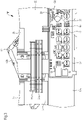
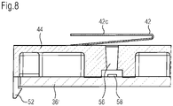
- Fig. 6 shows the second embodiment of the user interface 20 in a top view. Further, this figure also indicates the localisation of two sectional views of segments of the user interface 20 according to sections VII - VII (illustrated in Fig. 7 ) and VIII - VIII (illustrated in Fig. 8 ).
- the sectional view of segment VII - VII according to Fig. 7 shows the fixation of the touch key elements 42 by the retainer element 42, more specifically by a tongue shaped portion 46 of the retainer element 44.
- the retainer element 44 including its tongue shaped portion 46 are made of a plastic material, preferably produced by injection moulding, and the touch key elements 42, more specifically a vertically oriented short intermediate section 48 thereof, are embedded in the plastic material of the tongue shaped portion 46, which has been performed in an over-moulding process.
- Fig. 7 also shows the shaping of the touch key elements 42, which, in a side view, are designed in a Z-shape and functionally acting as a Z-shaped spring element, being elastically compressible in vertical direction.
- a touch key element is divisible in a lower section 42a, a middle section 42b and an upper section 42c.
- the compressibility of the touch key element is implemented in its Z-shaped middle section 42b, which is foldable in an accordion manner, but in an elastic way.
- a major portion of the Z-shaped middle section 42b is arranged above the tongue shaped portion 46 of the retainer element 44 and only a predominant part of the lower section 42a is arranged below the tongue shaped portion 46.
- the lower section 42a is designed like a leaf spring, an end section 50 thereof being bent off in a trough-shaped manner, which end section 50 forming a contact area for contacting a solder pad or a conductor path of the circuit on the user interface board 36'.
- the upper section 42c of the touch key element 42 forms the above-mentioned square-shaped touch key surface.
- said touch key surface is pressed against the lower surface of the glass panel 14 thereby forming the touch sensitive area on the upper side of the glass panel.
- the middle section 42b of the touch key element 42 is elastically compressed.
- the mechanical connection of the retainer element 44 and the user interface board 36' is realized by means of a snap coupling.
- snap-in hooks 52 are integrally formed with the retainer element 44, which snap-in hooks 52 are configured to snap in allocated notches 54 at edges of the user interface board 36'. With snap-in hooks 52 snapped in the allocated edges 54, the end section 50 of the lower section 42a of the touch key element 42 is pressed against the solder pad or the conductor path on the user interface circuit, with the lower section 42a being set under preload.
- the retainer element 44 also includes a light guide element 56, transmitting a light signal emitted by a light source 58, which is also part of the user interface circuit, to a respective display area on the user interface zone 21 for providing optical information to the user.
Landscapes
- Engineering & Computer Science (AREA)
- Chemical & Material Sciences (AREA)
- Combustion & Propulsion (AREA)
- Mechanical Engineering (AREA)
- General Engineering & Computer Science (AREA)
- Electric Stoves And Ranges (AREA)
Priority Applications (1)
| Application Number | Priority Date | Filing Date | Title |
|---|---|---|---|
| EP20208545.2A EP4001767A1 (fr) | 2020-11-19 | 2020-11-19 | Dispositif d'interaction d'utilisateur, appareil domestique et procédé de fabrication d'un dispositif d'interaction d'utilisateur |
Applications Claiming Priority (1)
| Application Number | Priority Date | Filing Date | Title |
|---|---|---|---|
| EP20208545.2A EP4001767A1 (fr) | 2020-11-19 | 2020-11-19 | Dispositif d'interaction d'utilisateur, appareil domestique et procédé de fabrication d'un dispositif d'interaction d'utilisateur |
Publications (1)
| Publication Number | Publication Date |
|---|---|
| EP4001767A1 true EP4001767A1 (fr) | 2022-05-25 |
Family
ID=73497540
Family Applications (1)
| Application Number | Title | Priority Date | Filing Date |
|---|---|---|---|
| EP20208545.2A Withdrawn EP4001767A1 (fr) | 2020-11-19 | 2020-11-19 | Dispositif d'interaction d'utilisateur, appareil domestique et procédé de fabrication d'un dispositif d'interaction d'utilisateur |
Country Status (1)
| Country | Link |
|---|---|
| EP (1) | EP4001767A1 (fr) |
Citations (5)
| Publication number | Priority date | Publication date | Assignee | Title |
|---|---|---|---|---|
| EP0858166A1 (fr) * | 1997-02-07 | 1998-08-12 | Jaeger Regulation Société Anonyme | Clavier étanche et appareil de cuisson comportant un tel clavier |
| WO2015074851A1 (fr) * | 2013-11-21 | 2015-05-28 | Electrolux Appliances Aktiebolag | Appareil électroménager comprenant un tableau de commande |
| CN206041027U (zh) * | 2016-07-19 | 2017-03-22 | 广东欧珀移动通信有限公司 | 壳体装置、连接结构及终端设备 |
| EP3358746A1 (fr) * | 2017-02-03 | 2018-08-08 | Bitron S.p.A. | Ensemble comprenant une plaquette de circuits imprimés et un ressort a spirale |
| DE102019000295A1 (de) * | 2019-01-16 | 2020-07-16 | Diehl Ako Stiftung & Co. Kg | Kapazitiver Berührungsschalter |
-
2020
- 2020-11-19 EP EP20208545.2A patent/EP4001767A1/fr not_active Withdrawn
Patent Citations (5)
| Publication number | Priority date | Publication date | Assignee | Title |
|---|---|---|---|---|
| EP0858166A1 (fr) * | 1997-02-07 | 1998-08-12 | Jaeger Regulation Société Anonyme | Clavier étanche et appareil de cuisson comportant un tel clavier |
| WO2015074851A1 (fr) * | 2013-11-21 | 2015-05-28 | Electrolux Appliances Aktiebolag | Appareil électroménager comprenant un tableau de commande |
| CN206041027U (zh) * | 2016-07-19 | 2017-03-22 | 广东欧珀移动通信有限公司 | 壳体装置、连接结构及终端设备 |
| EP3358746A1 (fr) * | 2017-02-03 | 2018-08-08 | Bitron S.p.A. | Ensemble comprenant une plaquette de circuits imprimés et un ressort a spirale |
| DE102019000295A1 (de) * | 2019-01-16 | 2020-07-16 | Diehl Ako Stiftung & Co. Kg | Kapazitiver Berührungsschalter |
Similar Documents
| Publication | Publication Date | Title |
|---|---|---|
| US20250344295A1 (en) | Induction coil compression apparatus for beam assembly | |
| US7786414B2 (en) | Induction heating device and hob having such an induction heating device | |
| US5917165A (en) | Touch switch with flexible, intermediate conductive spacer as sensor button | |
| US11405989B2 (en) | Temperature sensor compression features for induction cooktop assembly | |
| CN110300471B (zh) | 感应烹饪器具 | |
| CN111261445A (zh) | 控制装置 | |
| US9195088B2 (en) | Operating device for an electric appliance | |
| EP2662981A1 (fr) | Commutateur de proximité et/ou de contact capacitive avec électrode flottante | |
| CN101320896B (zh) | 传感装置 | |
| EP3996470B1 (fr) | Appareil de cuisson à induction comportant un dissipateur thermique | |
| EP1244127A2 (fr) | Elément de commutation électrique | |
| EP4001767A1 (fr) | Dispositif d'interaction d'utilisateur, appareil domestique et procédé de fabrication d'un dispositif d'interaction d'utilisateur | |
| EP3975663A1 (fr) | Ensemble capteur de température pour plaque de cuisson à induction | |
| GB2044427A (en) | Domestic or industrial appliances | |
| PL184586B1 (pl) | Zespół montażowy sterujący zwłaszcza dla kuchni do gotowania i lub pieczenia | |
| JP7117637B2 (ja) | 加熱調理器 | |
| KR101049120B1 (ko) | 건조기의 pcb 고정 인슐레이터 | |
| EP3982047B1 (fr) | Appareil domestique et procédé d'établissement d'une connexion électrique d'un circuit imprimé dans ledit appareil | |
| JPWO2019058556A1 (ja) | 空気調和機 | |
| EP3986091B1 (fr) | Appareil domestique et procédé d'assemblage de l'appareil domestique | |
| CN114251689A (zh) | 用于感应式炉灶的温度传感器组件 | |
| KR19990017335U (ko) | 전자렌지용 버튼의 구조 | |
| EP4015916A1 (fr) | Appareil domestique et procédé d'assemblage de l'appareil domestique | |
| CN112217501A (zh) | 传感器元件装置、操作装置和具有该操作装置的电气设备 | |
| EP2733715A1 (fr) | Dispositif de commande |
Legal Events
| Date | Code | Title | Description |
|---|---|---|---|
| PUAI | Public reference made under article 153(3) epc to a published international application that has entered the european phase |
Free format text: ORIGINAL CODE: 0009012 |
|
| STAA | Information on the status of an ep patent application or granted ep patent |
Free format text: STATUS: THE APPLICATION HAS BEEN PUBLISHED |
|
| AK | Designated contracting states |
Kind code of ref document: A1 Designated state(s): AL AT BE BG CH CY CZ DE DK EE ES FI FR GB GR HR HU IE IS IT LI LT LU LV MC MK MT NL NO PL PT RO RS SE SI SK SM TR |
|
| STAA | Information on the status of an ep patent application or granted ep patent |
Free format text: STATUS: THE APPLICATION IS DEEMED TO BE WITHDRAWN |
|
| 18D | Application deemed to be withdrawn |
Effective date: 20221126 |