EP0858304B1 - Einspritzgerät mit deformierbaren kolbenspitze für verfombare intraokularlinse - Google Patents
Einspritzgerät mit deformierbaren kolbenspitze für verfombare intraokularlinse Download PDFInfo
- Publication number
- EP0858304B1 EP0858304B1 EP96936995A EP96936995A EP0858304B1 EP 0858304 B1 EP0858304 B1 EP 0858304B1 EP 96936995 A EP96936995 A EP 96936995A EP 96936995 A EP96936995 A EP 96936995A EP 0858304 B1 EP0858304 B1 EP 0858304B1
- Authority
- EP
- European Patent Office
- Prior art keywords
- deformable
- lens
- plunger
- tip
- delivery passageway
- Prior art date
- Legal status (The legal status is an assumption and is not a legal conclusion. Google has not performed a legal analysis and makes no representation as to the accuracy of the status listed.)
- Expired - Lifetime
Links
- 239000000463 material Substances 0.000 claims abstract description 29
- 239000006260 foam Substances 0.000 claims description 12
- 239000004033 plastic Substances 0.000 claims description 11
- 229920003023 plastic Polymers 0.000 claims description 11
- 229920001971 elastomer Polymers 0.000 claims description 5
- 239000005060 rubber Substances 0.000 claims description 4
- 239000007788 liquid Substances 0.000 claims description 2
- 239000007779 soft material Substances 0.000 claims 1
- 230000006835 compression Effects 0.000 description 8
- 238000007906 compression Methods 0.000 description 8
- XLYOFNOQVPJJNP-UHFFFAOYSA-N water Substances O XLYOFNOQVPJJNP-UHFFFAOYSA-N 0.000 description 6
- 229910052751 metal Inorganic materials 0.000 description 4
- 239000002184 metal Substances 0.000 description 4
- 229920001296 polysiloxane Polymers 0.000 description 4
- 239000011800 void material Substances 0.000 description 4
- 239000000853 adhesive Substances 0.000 description 3
- 230000001070 adhesive effect Effects 0.000 description 3
- 238000002513 implantation Methods 0.000 description 3
- 238000003780 insertion Methods 0.000 description 3
- 230000037431 insertion Effects 0.000 description 3
- FAPWRFPIFSIZLT-UHFFFAOYSA-M Sodium chloride Chemical compound [Na+].[Cl-] FAPWRFPIFSIZLT-UHFFFAOYSA-M 0.000 description 2
- RTAQQCXQSZGOHL-UHFFFAOYSA-N Titanium Chemical compound [Ti] RTAQQCXQSZGOHL-UHFFFAOYSA-N 0.000 description 2
- 238000010276 construction Methods 0.000 description 2
- 210000003811 finger Anatomy 0.000 description 2
- 229920002492 poly(sulfone) Polymers 0.000 description 2
- -1 polypropylene Polymers 0.000 description 2
- 239000007787 solid Substances 0.000 description 2
- 239000010935 stainless steel Substances 0.000 description 2
- 229910001220 stainless steel Inorganic materials 0.000 description 2
- 239000000126 substance Substances 0.000 description 2
- 210000003813 thumb Anatomy 0.000 description 2
- 239000010936 titanium Substances 0.000 description 2
- 229910052719 titanium Inorganic materials 0.000 description 2
- 238000003466 welding Methods 0.000 description 2
- 229920006367 Neoflon Polymers 0.000 description 1
- 239000004698 Polyethylene Substances 0.000 description 1
- 239000004743 Polypropylene Substances 0.000 description 1
- 238000010521 absorption reaction Methods 0.000 description 1
- DHKHKXVYLBGOIT-UHFFFAOYSA-N acetaldehyde Diethyl Acetal Natural products CCOC(C)OCC DHKHKXVYLBGOIT-UHFFFAOYSA-N 0.000 description 1
- 125000002777 acetyl group Chemical class [H]C([H])([H])C(*)=O 0.000 description 1
- 239000000919 ceramic Substances 0.000 description 1
- 239000012141 concentrate Substances 0.000 description 1
- 230000007423 decrease Effects 0.000 description 1
- 239000000806 elastomer Substances 0.000 description 1
- HIDUXZXZQUHSBT-UHFFFAOYSA-N ethenol;formaldehyde Chemical compound O=C.OC=C HIDUXZXZQUHSBT-UHFFFAOYSA-N 0.000 description 1
- 239000000314 lubricant Substances 0.000 description 1
- 230000001050 lubricating effect Effects 0.000 description 1
- 238000000034 method Methods 0.000 description 1
- 229920000573 polyethylene Polymers 0.000 description 1
- 229920001155 polypropylene Polymers 0.000 description 1
- 229920002635 polyurethane Polymers 0.000 description 1
- 239000004814 polyurethane Substances 0.000 description 1
- 229920002451 polyvinyl alcohol Polymers 0.000 description 1
- 238000002360 preparation method Methods 0.000 description 1
- 239000011347 resin Substances 0.000 description 1
- 229920005989 resin Polymers 0.000 description 1
- 239000012266 salt solution Substances 0.000 description 1
- 238000007790 scraping Methods 0.000 description 1
- 229920002050 silicone resin Polymers 0.000 description 1
- 229920001169 thermoplastic Polymers 0.000 description 1
- 239000004416 thermosoftening plastic Substances 0.000 description 1
- 229920002554 vinyl polymer Polymers 0.000 description 1
Images



Classifications
-
- A—HUMAN NECESSITIES
- A61—MEDICAL OR VETERINARY SCIENCE; HYGIENE
- A61F—FILTERS IMPLANTABLE INTO BLOOD VESSELS; PROSTHESES; DEVICES PROVIDING PATENCY TO, OR PREVENTING COLLAPSING OF, TUBULAR STRUCTURES OF THE BODY, e.g. STENTS; ORTHOPAEDIC, NURSING OR CONTRACEPTIVE DEVICES; FOMENTATION; TREATMENT OR PROTECTION OF EYES OR EARS; BANDAGES, DRESSINGS OR ABSORBENT PADS; FIRST-AID KITS
- A61F9/00—Methods or devices for treatment of the eyes; Devices for putting in contact-lenses; Devices to correct squinting; Apparatus to guide the blind; Protective devices for the eyes, carried on the body or in the hand
-
- A—HUMAN NECESSITIES
- A61—MEDICAL OR VETERINARY SCIENCE; HYGIENE
- A61F—FILTERS IMPLANTABLE INTO BLOOD VESSELS; PROSTHESES; DEVICES PROVIDING PATENCY TO, OR PREVENTING COLLAPSING OF, TUBULAR STRUCTURES OF THE BODY, e.g. STENTS; ORTHOPAEDIC, NURSING OR CONTRACEPTIVE DEVICES; FOMENTATION; TREATMENT OR PROTECTION OF EYES OR EARS; BANDAGES, DRESSINGS OR ABSORBENT PADS; FIRST-AID KITS
- A61F2/00—Filters implantable into blood vessels; Prostheses, i.e. artificial substitutes or replacements for parts of the body; Appliances for connecting them with the body; Devices providing patency to, or preventing collapsing of, tubular structures of the body, e.g. stents
- A61F2/02—Prostheses implantable into the body
- A61F2/14—Eye parts, e.g. lenses or corneal implants; Artificial eyes
- A61F2/16—Intraocular lenses
- A61F2/1662—Instruments for inserting intraocular lenses into the eye
- A61F2/167—Instruments for inserting intraocular lenses into the eye with pushable plungers
-
- A—HUMAN NECESSITIES
- A61—MEDICAL OR VETERINARY SCIENCE; HYGIENE
- A61F—FILTERS IMPLANTABLE INTO BLOOD VESSELS; PROSTHESES; DEVICES PROVIDING PATENCY TO, OR PREVENTING COLLAPSING OF, TUBULAR STRUCTURES OF THE BODY, e.g. STENTS; ORTHOPAEDIC, NURSING OR CONTRACEPTIVE DEVICES; FOMENTATION; TREATMENT OR PROTECTION OF EYES OR EARS; BANDAGES, DRESSINGS OR ABSORBENT PADS; FIRST-AID KITS
- A61F2/00—Filters implantable into blood vessels; Prostheses, i.e. artificial substitutes or replacements for parts of the body; Appliances for connecting them with the body; Devices providing patency to, or preventing collapsing of, tubular structures of the body, e.g. stents
- A61F2/02—Prostheses implantable into the body
- A61F2/14—Eye parts, e.g. lenses or corneal implants; Artificial eyes
- A61F2/16—Intraocular lenses
- A61F2/1662—Instruments for inserting intraocular lenses into the eye
- A61F2/1664—Instruments for inserting intraocular lenses into the eye for manual insertion during surgery, e.g. forceps-like instruments
-
- A—HUMAN NECESSITIES
- A61—MEDICAL OR VETERINARY SCIENCE; HYGIENE
- A61F—FILTERS IMPLANTABLE INTO BLOOD VESSELS; PROSTHESES; DEVICES PROVIDING PATENCY TO, OR PREVENTING COLLAPSING OF, TUBULAR STRUCTURES OF THE BODY, e.g. STENTS; ORTHOPAEDIC, NURSING OR CONTRACEPTIVE DEVICES; FOMENTATION; TREATMENT OR PROTECTION OF EYES OR EARS; BANDAGES, DRESSINGS OR ABSORBENT PADS; FIRST-AID KITS
- A61F2/00—Filters implantable into blood vessels; Prostheses, i.e. artificial substitutes or replacements for parts of the body; Appliances for connecting them with the body; Devices providing patency to, or preventing collapsing of, tubular structures of the body, e.g. stents
- A61F2/02—Prostheses implantable into the body
- A61F2/14—Eye parts, e.g. lenses or corneal implants; Artificial eyes
- A61F2/16—Intraocular lenses
- A61F2/1662—Instruments for inserting intraocular lenses into the eye
- A61F2/1678—Instruments for inserting intraocular lenses into the eye with a separate cartridge or other lens setting part for storage of a lens, e.g. preloadable for shipping
-
- A—HUMAN NECESSITIES
- A61—MEDICAL OR VETERINARY SCIENCE; HYGIENE
- A61F—FILTERS IMPLANTABLE INTO BLOOD VESSELS; PROSTHESES; DEVICES PROVIDING PATENCY TO, OR PREVENTING COLLAPSING OF, TUBULAR STRUCTURES OF THE BODY, e.g. STENTS; ORTHOPAEDIC, NURSING OR CONTRACEPTIVE DEVICES; FOMENTATION; TREATMENT OR PROTECTION OF EYES OR EARS; BANDAGES, DRESSINGS OR ABSORBENT PADS; FIRST-AID KITS
- A61F2/00—Filters implantable into blood vessels; Prostheses, i.e. artificial substitutes or replacements for parts of the body; Appliances for connecting them with the body; Devices providing patency to, or preventing collapsing of, tubular structures of the body, e.g. stents
- A61F2/02—Prostheses implantable into the body
- A61F2/14—Eye parts, e.g. lenses or corneal implants; Artificial eyes
- A61F2/16—Intraocular lenses
- A61F2/1662—Instruments for inserting intraocular lenses into the eye
- A61F2/1667—Instruments for inserting intraocular lenses into the eye with rotatable plungers
Definitions
- the present invention is directed to a lens injecting apparatus including a deformable tip plunger for implantation of a deformable intraocular lens into the eye.
- the lens injecting apparatus currently in use comprises two (2) separate components including 1) a lens injecting device including a cylindrical barrel having a lens cartridge receiver and a movable plunger disposed with the cylindrical barrel; and 2) a lens cartridge including a lens holding portion connected to a nozzle portion.
- the movable plunger of the lens injecting device includes a tip for forcing a deformable intraocular lens loaded into the lens cartridge through a delivery passageway extending through the lens cartridge and out of the tip of the nozzle portion of the lens cartridge.
- the movable plunger of the lens injecting device is slidable through an initial length of movement of the plunger, and then is threadedly advanced through a final length of movement of the plunger when forcing the deformable intraocular lens through the delivery passageway of the lens cartridge.
- the lens injecting device including the plunger is made of titanium, plastic or stainless steel and the lens cartridge is made of plastic.
- the metal tip of the plunger has a fixed configuration. Specifically, the tip has a faceted configuration including a concave gripping surface portion and other surface portions defining the fixed geometry of the plunger tip.
- a first object of the present invention is to provide a deformable intraocular lens injecting apparatus having a plunger with a deformable plunger tip.
- a second object of the present invention is to provide a deformable intraocular lens injecting apparatus having a plunger with a compressible tip with a resiliently deformable plunger tip.
- a third object of the present invention is to provide a deformable intraocular lens injecting apparatus having an inwardly tapering delivery passageway in the direction of insertion of the deformable intraocular lens and a plunger having a deformable plunger tip cooperating with the inwardly tapering passageway, and being compressed as advanced through the inwardly tapering passageway.
- a lens injecting apparatus comprising a body portion having a lens delivery passageway, a movable plunger having a deformable tip for advancing through the delivery passageway and forcing the deformable intraocular lens through the delivery passageway, characterised in that said deformable tip is made of an expandable material that can absorb liquid and swell.
- the present invention is directed to a lens injecting apparatus for implantation of a deformable intraocular lens into the eye.
- the lens injecting apparatus can have a one-piece construction (i.e. no lens cartridge) or can have a multi-piece construction including a separate lens injecting device having a lens cartridge receiver, and a separate lens cartridge.
- the one-piece lens injecting apparatus includes a body portion having a lens delivery passageway extending therethrough and a movable plunger.
- the plunger can be slidably disposed within the delivery passageway, or the movement of the plunger can be limited such as by being threadedly advanced through the delivery passageway.
- the one-piece lens injecting apparatus includes an opening or port for loading the deformable intraocular lens into the delivery passageway of the lens injecting apparatus.
- the multi-piece lens injecting apparatus includes a separate lens injecting device having a lens cartridge receiver and a separate lens cartridge.
- the lens injecting device includes a passageway for accommodating a movable plunger. The passageway of the lens injecting device extends into a lens delivery passageway of the lens cartridge when the lens cartridge is loaded into the lens cartridge receiver of the lens injecting device.
- the plunger used in the one-piece lens injecting apparatus or the multi-piece lens injecting apparatus is provided with a deformable tip.
- the deformable tip of the plunger is advantageous over a fixed configuration, since the deformable tip is made of deformable materials such as plastic, rubber, resin, foam, sponge, or other suitable material. These deformable materials are substantially softer materials compared with the fixed configuration tip of a metal or hard plastic plunger.
- the deformable tip plunger according to the present invention is substantially less likely to damage deformable intraocular lenses, in particular delicate and thin deformable intraocular contact lenses (ICLs).
- the deformable tip plunger according to the present invention is made of a material having smaller dimensional size when dry and expandable to a larger dimensional size upon absorption of water or other suitable chemical. This would allow the plunger tip to be easily loaded and potentially stored in its smaller outer dimensional size, and then expand to its larger outer dimensional size mode upon contact with water or other suitable chemical (e.g ., lubricating medium) at the time of use.
- suitable chemical e.g ., lubricating medium
- the deformable foam plunger tip absorbs and increases its size, thus ensuring a tight fit with the inner walls of the cartridge delivery passageway. Further, the foam in this expanded condition is soft and highly pliable preventing any damage to the deformable intraocular lens.
- the deformable tip plunger prevents the deformable intraocular lens or portions of the deformable intraocular lens, in particular the trailing haptic, from being caught between the plunger tip and inner wall of the delivery passageway when the plunger tip is being advanced forcing the deformable intraocular lens through the delivery passageway.
- the deformable plunger tip can be sized to be slightly oversized compared to the inner dimensions of the delivery passageway so that the plunger tip is under slight compression when positioned within the delivery passageway. The radially outwardly directed compression force prevents the deformable intraocular lens or portion of the deformable intraocular lens from inadvertently moving or being forced between the exterior surface of the plunger tip and the inner wall surface of the delivery passageway.
- the lens injecting apparatus is provided with an inwardly tapering delivery passageway in the direction of delivery of the deformable intraocular lens.
- the cross-sectional size decreases in the direction of delivery to further fold, compress or otherwise reduce the cross-sectional size of the deformable intraocular lens as it is advanced through the delivery passageway.
- the deformable plunger tip according to the present invention is particularly suitable for an inwardly tapering delivery passageway, since the deformable plunger tip can be further and further compressed and reduced in outer dimensions as it is advanced through the inwardly tapering delivery passageway. This configuration allows the outer dimensions of the deformable plunger tip of the lens injecting apparatus to be further reduced to allow this tip to be inserted through a smaller sized incision in the eye.
- the present invention is directed to a lens injecting apparatus having a plunger with a deformable plunger tip.
- the deformable plunger tip allows the plunger tip to conform to the shape of the delivery passageway for the deformable intraocular lens through the lens injecting apparatus, in particular through an inwardly tapering passageway.
- the deformable plunger tip is preferably resiliently deformable so that the deformable plunger tip can be deformed or compressed and then return to its original shape once the deformation or compression forces are removed.
- the deformable plunger is made of elastomer (e.g. , silicone), deformable plastic, deformable thermoplastic, rubber, foam, sponge, COLLAMER made by STAAR Surgical, or other suitable resiliently deformable material.
- a particularly suitable material for making the deformable tip according to the present invention is a surgical sponge material produced from cross-linked polyvinyl acetal (PVA) made by MEROCEL of Mistic, Connecticut.
- the plunger tip applies a wiping force between the outer surface of the plunger tip and the inner surface of the delivery passageway through the lens injecting apparatus. In this manner, a trailing haptic of the deformable intraocular lens cannot be caught between the plunger tip and delivery passageway when the plunger tip is forcing the deformable intraocular lens through the delivery passageway.
- the deformable tip is made out of foam or spongy material, it can be smaller than the opening of the delivery passageway. When it comes into contact with water or balance salt solution, it expands and fills up completely the dimensions of the passageway.
- the deformable plunger tip is preferably made of a soft resiliently deformable material to prevent any surface or internal damage to the deformable intraocular lens when the deformable plunger tip is being forced through the delivery passageway.
- the deformable plunger tip can be made of essentially the same material as the particular deformable intraocular lens (e.g. , silicone and COLLAMER made by STAAR Surgical Company).
- the deformable plunger tip according to the present invention can be embodied in various lens injecting devices.
- the present invention is applicable to a one-piece lens injecting device, which is a single piece once assembled, or a multi-piece lens injecting apparatus including a separate lens injecting device having a lens cartridge receiver, and a separate lens cartridge.
- FIG. 1 A preferred one-piece lens injecting apparatus 10 according to the present invention is shown in Figs. 1-4.
- the one-piece lens injecting apparatus 10 comprises 1) a body portion 12 having a lens receiver 14 for a deformable intraocular lens 15 and a lens delivery passageway 16 extending therethrough; and 2) a plunger 18 movably disposed within said body portion 12.
- the plunger 18 is provided with a plunger grip 20 and a deformable plunger tip 22.
- the body portion 12 comprises a lens receiving portion 12a having a uniform cross-sectional sized and shaped delivery passageway portion 16a leading into a nozzle portion 12b having an inwardly tapering passageway portion 16b.
- the inner surfaces of the nozzle portion 16b defining the inwardly tapering delivery passageway portion 16b can be contoured ( e.g. , provided with ridges, grooves or other configuration) for folding and further folding the deformable intraocular lens 15 as it is forced through the inwardly tapering delivery passageway portion 16b by the deformable plunger tip 22.
- the one end of the lens receiving portion 12a accommodates the plunger 18 to allow sliding movement of the plunger 18 inside the lens receiving portion 12a.
- the nozzle portion 12b is provided with a nozzle tip 24 accommodating the exit end of the delivery passageway 16.
- the body portion 12 is provided with a slidable collar 26, which opens and closes the lens receiver 14 for loading or inspecting the deformable intraocular lens 15.
- the body portion 12 is also provided with two sets of stops 28 and 30 to limit movement of the slidable collar.
- the deformable plunger tip 22 preferably has the same or similar cross-sectional size and shape as the delivery passageway 16.
- the deformable plunger tip 22 is slightly oversized compared with the inner dimensions of the delivery passageway portion 16a so that the deformable plunger tip 22 is under a slight compression to prevent a trailing haptic of the deformable intraocular lens 15 from moving in between the outer surface of the deformable plunger tip 22 and the inner surface of the delivery passageway portion 16a.
- the deformable plunger tip 22 When the deformable plunger tip 22 reaches the inwardly tapering delivery passageway portion 16b, the deformable plunger tip 22 is further and further compressed and its outer surface tapers inwardly and conforms to the inwardly tapering delivery passageway portion 16b, as shown in Fig. 4.
- the compression stress at the interface between the outer surface of the deformable plunger tip 22 and inner surface of the delivery passageway portion 16b significantly increases making it more difficult for the trailing haptic of the deformable intraocular lens 15 to move in between the outer surface of the deformable plunger tip 22 and the inner surface of the delivery passageway portion 16a.
- This increased compression at the interface between the outer surface of the deformable plunger tip 22 and the inner surface of the delivery passageway portion 16b is necessary to counteract the increasing compression stresses on the deformable intraocular lens causing the deformable intraocular lens to move towards and seek any void space or weak wall surface inside the delivery passageway ( i .
- the deformable intraocular lens 15 will continue to advance forward while being further compressed as it moves towards and exits the nozzle tip 24.
- the deformable plunger tip 22 also has the same cross-sectional shape (e . g ., oval, round, curved, contoured, grooved) as the cross-sectional shape of the delivery passageway 16, again to prevent a trailing haptic of the deformable intraocular lens 15 from moving in between the outer surface of the deformable plunger tip 22 and the inner surface of the delivery passageway 16.
- cross-sectional shape e . g ., oval, round, curved, contoured, grooved
- the deformable plunger tip 22 is made of an expandable material (e.g ., foam). More specifically the deformable plunger tip 22 is made of a material that expands within the delivery passageway 16 upon contact with water or balanced saline solution. This type of deformable plunger tip 22 is very soft and highly pliable preventing any damage to the deformable intraocular lens. Further, the expansion of the material prevents the trailing haptic from getting caught between the deformable plunger tip 22 and the inner wall of the delivery passageway 16.
- an expandable material e.g ., foam
- the slidable collar 26 is slid to the left to open the lens receiver 14.
- the deformable intraocular lens 15 is then loaded in a flat configuration into the lens receiver 14 of the lens injecting apparatus 10.
- the slidable collar 26 in then slid to the right to close the lens receiver 14.
- the user exerts a force on the grip 20 with his or her fingers or thumb causing the plunger 18 to slide forward into contact with the deformable intraocular lens 15.
- the user continues to advance the plunger 18 so that the deformable intraocular lens 15 is moved through the delivery passageway portion 16a in a flat unstressed configuration and into the delivery passageway portion 16b to cause the lens to be folded and/or compressed.
- the lens injecting apparatus is now loaded, and readied for lens insertion.
- the user then inserts the tip of the nozzle tip 24 through a small incision in the eye, and then advances the plunger 18 so that the deformable intraocular lens 15 is folded or compressed as it passes through the inwardly tapering passageway portion 16b until it exits from the nozzle tip 24 inside the eye.
- the lens injecting apparatus 10 can be preloaded with the deformable intraocular lens 15 so that a user can slide the slidable collar to the left to open the lens receiver 14' to inspect the deformable intraocular lens 15, and then slide the slidable collar to the right to close the lens receiver 14.
- FIG. 3 A further preferred embodiment of a one-piece lens injecting apparatus 10', is shown in Fig. 3.
- the body portion 12' is not provided with a slidable collar 26 as in the embodiment shown in Figs 1 and 2. Instead, the lens receiver 14 is opened until the plunger tip 22' is advanced sufficiently forward to close off the opening into the delivery passageway 16.
- the deformable intraocular lens 15' is loaded in a flat configuration into the lens receiver 14' of the lens injecting apparatus 10'.
- the user exerts a force on the grip 20' with his or her fingers or thumb causing the plunger 18' to slide forward into contact with the deformable intraocular lens 15'.
- the user continues to advance the plunger 18' so that the deformable intraocular lens 15' is moved through the delivery passageway portion 16a' in a flat unstressed configuration.
- the lens injecting apparatus is now loaded, and readied for lens insertion.
- the user then inserts the tip of the nozzle tip 24' through a small incision in the eye, and then advances the plunger 18' so that the deformable intraocular lens 15' is folded or compressed as it passes through the inwardly tapering passageway portion 16b' until it exits from the nozzle tip 24' inside the eye.
- Figs. 5-17 A variety of deformable plunger tips designs are shown in Figs. 5-17.
- the plungers 18 are shown as being made of plastic, however, the plungers 18 can be made of metal, ceramic or other suitable material having sufficient structural strength and properties for proper operation thereof.
- the deformable plunger tips can be made to be deformable by 1) using a deformable material, preferably a resiliently deformable material; 2) using a configuration that allows deformation ( e.g. , hollow tip); or 3) both methods of 1 & 2; and/or 4) using a foam or sponge material so that the plunger tip absorbs water and swells to a larger size, thus, the expanded nature of the foam or sponge material is deformable.
- the deformable plunger tips are preferably made of resiliently deformable materials, since these materials tend to have "soft" surface properties that prevent damage to the deformable intraocular lenses during delivery.
- the deformable plunger tip 22 is provided on an end of the plunger 18. More specifically, the deformable plunger tip 22 is provided with a recess 22a for accommodating an end portion 18a having a reduced cross-sectional size compared with a main portion 18b of the plunger 18.
- the cross-sectional size of the recess 22a can be made slightly smaller than the cross-sectional size of the end portion 18a of the plunger 18 to provide an interference type fit.
- adhesive , welding, or other type of bonding can be provided between the deformable plunger tip 22 and plunger 18.
- the deformable plunger tip 22 is provided with a protrusion 22b received within a recess 18c in an end face of the plunger 18.
- the outer dimensions of the protrusion 22b can be made to be slightly larger than the inner dimensions of the recess 18c of the plunger 18 to provide an interference fit.
- adhesive, welding, or other type of bonding can be provided between the deformable plunger tip 22 and plunger 18.
- a substantial portion or the entire plunger 18 is coated with the deformable plunger tip 22.
- a silicone resin is molded around a more stiff plastic plunger 18.
- the deformable plunger tip 22 is provided with a protrusion 22c to provide a side clearance between the deformable plunger tip 22 and the delivery passageway to accommodate a trailing haptic, in particular the trailing haptic of a three (3) piece type deformable intraocular lens.
- the end face 22d contacts the optic of the deformable intraocular lens.
- the plunger 18 is provided with a threaded or barbed end portion 18d to enhance gripping with the deformable plunger tip 22.
- the recess 22e may also be threaded or barbed to further enhance gripping.
- the deformable plunger tip 22 is provided with a convex tip 22f.
- the deformable plunger tip 22 is provided with a slotted tip 22g to accommodate the trailing haptic of a plate type or three (3) piece type deformable intraocular lens.
- the deformable plunger tip 22 is provided with a set of wipers 22h to concentrate stress between the wipers and inner surface of the delivery passageway to prevent the trailing haptic of the deformable intraocular lens from getting caught in between the deformable plunger tip 22 and the inner surface of the delivery passageway.
- a single wiper or additional wipers can be provided.
- the plunger 18 is provided with a barbed end 18e to enhance gripping.
- a recess in the deformable plunger tip can be provided with a ridge 22i to cooperated with the barbed end 18e to further enhance gripping.
- a section of tubing 22j can be provided on the end of the plunger 18 to function as a deformable plunger tip 22.
- a section of soft polyurethane or silicone tubing is suitable.
- the section of tubing 22j can be attached by stretching due to its elastic resiliency ( i.e. stretched fit), and/or attached with adhesive or bonding.
- the inner passageway 22k in the tubing 22j can accommodate the trailing haptic of the deformable intraocular lens.
- the configuration of the section of tubing 22i having a void space inside provided by the inner passageway 22k enhances the deformability of the deformable plunger tip 22 ( i . e ., will deform inwardly with less compressive stress compared to solid type tip).
- the deformable plunger tip 22 is provided with a void space 221 to enhance the deformability of the deformable plunger tip 22 ( i.e ., will deform inwardly with less compressive stress compared to solid type tip while still maintaining more resistance to compression at end face thereof).
- the void space 221 is shown as being round, however, other configurations such as rectangular, curved, multiple voids ( e.g ., foam or sponge) can be substituted.
- the deformable plunger tip 22 is provided with a concave end face 22m for capturing the trailing haptic of the deformable intraocular lens near the centerline of the delivery passageway, and maintaining the trailing haptic away from the inner walls of the delivery passageway.
- the deformable plunger tip 22 is provided with a scraper 22n for capturing the trailing haptic of the deformable intraocular lens near the centerline of the delivery passageway, and maintaining the trailing haptic away from the inner walls of the delivery passageway. Further, the scraper can deform inwardly under compressive force and apply a scraping spring force against the inner wall of the delivery passageway due to its cantilever configuration.
- the scraper 22n can have a cone shape, or be made of separate paddles.
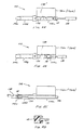
- Figs. 17A to 17G various transverse cross-sectional shapes of the deformable plunger tip are shown.
- the transverse cross-sectional shape of the plunger tip can remain fixed throughout its length or its transverse cross-sectional shape can vary along its length.
- a deformable plunger tip 22o having a circular transverse cross-sectional shape is shown in Fig. 17A.
- a deformable plunger tip 22p having an oval transverse cross-sectional shape is shown in Fig. 17B.
- a deformable plunger tip 22q having a triangular transverse cross-sectional shape is shown in Fig. 17C.
- a deformable plunger tip 22r having a rectangular ( e.g ., square) transverse cross-sectional shape is shown in Fig. 17D.
- a deformable plunger tip 22s having a pentagonal transverse cross-sectional shape is shown in Fig. 17E.
- a deformable plunger tip 22t having a hexagonal transverse cross-sectional shape is shown in Fig. 17F.
- a deformable plunger tip 22u having an octagonal transverse cross-sectional shape is shown in Fig. 17G.
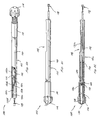
- a multi-piece lens injecting apparatus 100 according to the present invention is shown in Figs. 18-26.
- the multi-piece lens injecting apparatus 100 comprises a separate lens injecting device 102 and a separate lens cartridge 104.
- the lens injecting device 102 comprises a body portion 106 having a lens cartridge receiver 108 and an internally threaded end portion 110.
- a movable plunger 112 is disposed within the body portion 106.
- the movable plunger 112 is provided with a grip 114 having an externally threaded portion 116 at one end, and a plunger tip 118 at an opposite end (See Fig. 22) thereof.
- the plunger 112 is slidably disposed within the body portion 106.
- the body portion 106 is provided with an internally fitted guide 120, as shown in Fig. 22, for slidably supporting the plunger 112 within the body portion 106.
- the plunger 112 is advanced by sliding the plunger within the body portion 106 an initial distance until the externally threaded portion 116 of the grip 114 engages with the internally threaded portion 110 of the body portion 106.
- the grip 114 is rotated to threadedly advance the plunger 112 in a very accurate and controlled manner through a final distance causing the deformable intraocular lens to move through and out of the lens cartridge into the eye.
- the plunger 112 is provided with a threaded extension 122 passing through a hole in the end face 124 of the externally threaded end portion 116 of the grip 114, as shown in Fig. 22.
- a nut 126 is located inside a passageway 128 of the grip 114 and fastened onto the threaded extension 122 to connect the grip 114 to the end of the plunger 112.
- An end cap 130 is provided to seal the end of the passageway 128 in the grip 114.
- the lens cartridge receiver 108 of the body portion 106 is provided by an opening 132 in the side of the body portion 106.
- the opening 132 is defined by a set of wider spaced apart parallel edges 132a, a set of inwardly tapering edges 132b, a set of thinner spaced apart parallel edges 132c, and a stop edge 132d.
- the lens cartridge 104 is loaded in lens injecting device 102 through the opening 132 between the set of wider spaced apart parallel edges 132a of the lens cartridge receiver 108. Then the lens cartridge 104 is moved forward within the lens cartridge receiver 108.
- the plunger tip 118 is made of a deformable material, preferable a resilient deformable material such as plastic, rubber, foam, sponge or other suitable material.
- the remaining parts of the lens injecting device can be made of structural grade plastic (e.g ., polysulfone) or metal (e.g ., stainless steel or titanium) allowing autoclaving thereof.
- the lens cartridge 104 is preferably made of plastic (e.g ., polypropylene, polysulfone, Neoflon, polyethylene and silicone), and has a foldable design, as shown in Fig. 18. As shown in Fig. 23, the lens cartridge 104 includes a lens holding portion 104a connected to a nozzle portion 104b having a nozzle tip 104c. A delivery passageway 134 extends throughout the length of the lens cartridge 104. The lens cartridge further includes a pair of extensions 136a and 136b for opening and closing the lens cartridge 104. Further, the extensions 136a and 136b cooperate with the edges 132a, 132b and 132c of the opening 132 of the lens cartridge receiver 108.
- plastic e.g ., polypropylene, polysulfone, Neoflon, polyethylene and silicone
- the lens cartridge 104 is loaded with a deformable intraocular lens and a viscoelastic lubricant.
- the lens cartridge 104 is then loaded into the lens cartridge receiver 108 of the lens injecting device 102.
- the lens cartridge is inserted through the opening 132 of the lens cartridge receiver 108 and then moved forward so that the extensions are squeezed together by the set of inwardly tapering edges 132b and the set of thinner parallel set apart edges 132c until the extensions reach the edge stop 132d.
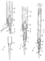
- the plunger 132 is then advanced forward so that the deformable plunger tip 118 enters one end of the delivery passageway 134, as shown in Fig. 23.
- the plunger tip 118 is further advanced into contact with the deformable intraocular lens 138 to begin the forcing and advancing of the deformable intraocular lens through the delivery passageway 134.
- the deformable plunger tip 118 begins to deform inwardly when entering the inwardly tapering portion of the delivery passageway 134 located in the nozzle tip 104c.
- Final advancement of the plunger tip 118 causes the deformable intraocular lens 138 to exit the nozzle tip 104c.
- FIG. 27 and 28 Another embodiment of the lens cartridge 104' is shown in Figs. 27 and 28.
- the deformable intraocular lens is loaded into the delivery passageway 134' of the lens cartridge 104' with the trailing haptic 138a of the deformable intraocular lens 138 extending from the delivery passageway 134'.
- the deformable plunger tip 118 is pushed into the end of the delivery passageway 134' in a manner so that the trailing haptic 138a is not caught between the deformable plunger tip 118 and inner wall of the delivery passageway 134'.
- the trailing haptic 138a is gently contacted.by the end face of the deformable plunger tip 118 and manipulated ( e.g.
- FIG. 29-31 A further embodiment of a deformable intraocular lens injecting apparatus 200 is shown in Figs. 29-31.
- the lens injecting apparatus 200 comprises three (3) separate components including 1) a lens injecting device 202 containing a slidable plunger 204 and a lens cartridge receiver 206; 2) a transverse hinged lens cartridge 208 having an upper portion 210 and a lower portion 212 connected together by a transverse hinge 214; and 3) a nozzle portion 216.
- the plunger 202 is provided with a deformable plunger tip 218 for cooperating with an inwardly tapering delivery passageway 220 extending through the lens cartridge 208 and nozzle portion 216.
Landscapes
- Health & Medical Sciences (AREA)
- Ophthalmology & Optometry (AREA)
- Life Sciences & Earth Sciences (AREA)
- Engineering & Computer Science (AREA)
- Biomedical Technology (AREA)
- Heart & Thoracic Surgery (AREA)
- Vascular Medicine (AREA)
- Animal Behavior & Ethology (AREA)
- General Health & Medical Sciences (AREA)
- Public Health (AREA)
- Veterinary Medicine (AREA)
- Oral & Maxillofacial Surgery (AREA)
- Transplantation (AREA)
- Cardiology (AREA)
- Prostheses (AREA)
Claims (9)
- Linseneinführungsvorrichtung, umfassend einen Körperabschnitt (12), welcher einen Durchgangsweg zur Linsenübertragung (16) und einen beweglichen Kolben (18) aufweist, der eine verformbare Spitze (22) zum Vorschieben durch den Durchgangsweg zur Übertragung (16) und zum Bewegen der verformbaren intraokularen Linse (15) durch den Durchgangsweg zur Übertragung (16) aufweist, dadurch gekennzeichnet, dass die verformbare Spitze (22) aus einem expandierbaren Material hergestellt ist, welches Flüssigkeit absorbieren und schwellen kann.
- Vorrichtung nach Anspruch 1, worin die verformbare Spitze (22) aus Kunststoff, Gummi, Schaum oder Schwamm hergestellt ist.
- Vorrichtung nach Anspruch 1, worin die verformbare Spitze (22) aus einem federnden, verformbaren Material hergestellt ist, wie beispielsweise einem verhältnismäßig weichen Material.
- Vorrichtung nach einem der Ansprüche 1 bis 3, worin die verformbare Spitze (22) ein separates Stück ist, welches mit dem Kolben (18) verbunden ist.
- Vorrichtung nach einem der Ansprüche 1 bis 3, worin die verformbare Spitze (22) auf dem Kolben ausgebildet ist.
- Vorrichtung nach einem der Ansprüche 1 bis 5, worin der Durchgangsweg zur Linsenübertragung (16) ein sich einwärts in einer Richtung der Linsenübertragung verjüngender Durchgangsweg zur Übertragung (16b) ist.
- Vorrichtung nach einem der Ansprüche 1 bis 6, worin die Kolbenspitze (22) äußere Abmessungen aufweist, welche größer sind als innere Abmessungen des Durchgangswegs zur Übertragung (16), sodass die Kolbenspitze (22) komprimiert ist, wenn sie in dem Durchgangsweg zur Übertragung (16) positioniert ist.
- Vorrichtung nach Anspruch 2, worin wenigstens ein Abschnitt des Kolbens (18) aus einem verformbaren Material hergestellt ist, um die verformbare Spitze (22) bereitzustellen.
- Vorrichtung nach einem der Ansprüche 1 bis 8, worin die verformbare Kolbenspitze (22) eine flache Endfläche oder eine facettierte Spitzenkonfiguration aufweist.
Applications Claiming Priority (5)
| Application Number | Priority Date | Filing Date | Title |
|---|---|---|---|
| US08/547,908 US5616148A (en) | 1992-09-30 | 1995-10-25 | Transverse hinged deformable intraocular lens injecting apparatus |
| US547908 | 1995-10-25 | ||
| US08/570,564 US5772666A (en) | 1992-09-30 | 1995-12-11 | Deformable intraocular lens injecting apparatus with deformable tip plunger |
| PCT/US1996/017182 WO1997015253A1 (en) | 1995-10-25 | 1996-10-24 | Deformable intraocular lens injecting apparatus with deformable tip plunger |
| US570564 | 2000-05-12 |
Publications (3)
| Publication Number | Publication Date |
|---|---|
| EP0858304A1 EP0858304A1 (de) | 1998-08-19 |
| EP0858304A4 EP0858304A4 (de) | 1999-11-03 |
| EP0858304B1 true EP0858304B1 (de) | 2005-10-12 |
Family
ID=27068693
Family Applications (1)
| Application Number | Title | Priority Date | Filing Date |
|---|---|---|---|
| EP96936995A Expired - Lifetime EP0858304B1 (de) | 1995-10-25 | 1996-10-24 | Einspritzgerät mit deformierbaren kolbenspitze für verfombare intraokularlinse |
Country Status (12)
| Country | Link |
|---|---|
| US (2) | US5772666A (de) |
| EP (1) | EP0858304B1 (de) |
| JP (1) | JP4001627B2 (de) |
| KR (1) | KR19990067031A (de) |
| CN (1) | CN1200659A (de) |
| AT (1) | ATE306238T1 (de) |
| AU (1) | AU7476996A (de) |
| CA (1) | CA2234002C (de) |
| DE (1) | DE69635279T2 (de) |
| ES (1) | ES2251000T3 (de) |
| NZ (1) | NZ321437A (de) |
| WO (1) | WO1997015253A1 (de) |
Cited By (8)
| Publication number | Priority date | Publication date | Assignee | Title |
|---|---|---|---|---|
| US7901414B2 (en) | 2001-12-12 | 2011-03-08 | Ioltechnologie-Production | Cassette and injector for flexible intraocular lens and method for injecting such lenses |
| US8308799B2 (en) | 2010-04-20 | 2012-11-13 | Alcon Research, Ltd. | Modular intraocular lens injector device |
| US8308736B2 (en) | 2008-10-13 | 2012-11-13 | Alcon Research, Ltd. | Automated intraocular lens injector device |
| US8579969B2 (en) | 2010-07-25 | 2013-11-12 | Alcon Research, Ltd. | Dual mode automated intraocular lens injector device |
| US8657835B2 (en) | 2012-01-27 | 2014-02-25 | Alcon Research, Ltd. | Automated intraocular lens injector device |
| US8801780B2 (en) | 2008-10-13 | 2014-08-12 | Alcon Research, Ltd. | Plunger tip coupling device for intraocular lens injector |
| US8808308B2 (en) | 2008-10-13 | 2014-08-19 | Alcon Research, Ltd. | Automated intraocular lens injector device |
| US8894664B2 (en) | 2008-02-07 | 2014-11-25 | Novartis Ag | Lens delivery system cartridge |
Families Citing this family (140)
| Publication number | Priority date | Publication date | Assignee | Title |
|---|---|---|---|---|
| US6059791A (en) * | 1992-09-30 | 2000-05-09 | Staar Surgical Company, Inc. | Deformable intraocular lens injection system, and method thereof |
| US5653715A (en) | 1993-03-09 | 1997-08-05 | Chiron Vision Corporation | Apparatus for preparing an intraocular lens for insertion |
| US6174315B1 (en) * | 1994-02-15 | 2001-01-16 | Staar Surgical Company, Inc. | Spring biased deformable intraocular injecting apparatus |
| JP3704154B2 (ja) * | 1994-11-18 | 2005-10-05 | スター サージカル カンパニー | 眼内レンズ挿入システム |
| US5735858A (en) * | 1996-01-26 | 1998-04-07 | Allergan | IOL insertion apparatus and method for using same |
| AU731944B2 (en) | 1997-12-29 | 2001-04-05 | Duckworth & Kent Limited | Injectors for intraocular lenses |
| GB2335148B (en) * | 1997-12-29 | 2002-06-19 | Duckworth & Kent Ltd | Injectors for intraocular lenses |
| US6371960B2 (en) * | 1998-05-19 | 2002-04-16 | Bausch & Lomb Surgical, Inc. | Device for inserting a flexible intraocular lens |
| US6010510A (en) * | 1998-06-02 | 2000-01-04 | Alcon Laboratories, Inc. | Plunger |
| DE19904220C2 (de) * | 1999-02-03 | 2001-08-30 | Helmut Binder | Injektor zum Falten und Einbringen einer Intraokularlinse, und Behälter zum Lagern und Transportieren des Injektors |
| JP3040101B1 (ja) * | 1999-02-12 | 2000-05-08 | 毅 杉浦 | 眼球の後房レンズ経毛様体強膜縫着における毛様溝パッド |
| FR2789890B1 (fr) * | 1999-02-22 | 2002-01-18 | Lab Contactologie Appl Lca | Dispositif pour l'injection d'une lentille intra-oculaire en matiere souple |
| SE9904338D0 (sv) * | 1999-11-30 | 1999-11-30 | Pharmacia & Upjohn Ab | Intraocular lens implanter |
| US6283976B1 (en) | 2000-05-05 | 2001-09-04 | Allergan Sales Inc. | Intraocular lens implanting instrument |
| US7087080B2 (en) | 2001-01-25 | 2006-08-08 | Visiogen, Inc. | Materials for use in intraocular lens system |
| US6884261B2 (en) * | 2001-01-25 | 2005-04-26 | Visiogen, Inc. | Method of preparing an intraocular lens for implantation |
| US20030078657A1 (en) | 2001-01-25 | 2003-04-24 | Gholam-Reza Zadno-Azizi | Materials for use in accommodating intraocular lens system |
| WO2003011193A1 (en) * | 2001-08-02 | 2003-02-13 | Advanced Medical Optics, Inc. | Intraocular lens implanting instrument |
| US6537283B2 (en) | 2001-08-17 | 2003-03-25 | Alcon, Inc. | Intraocular lens shipping case and injection cartridge |
| US7037312B2 (en) * | 2001-09-07 | 2006-05-02 | Canon-Staar Co., Inc. | Insertion device for deformable intraocular lens |
| AU2002351647A1 (en) * | 2001-11-30 | 2003-06-10 | Medicel Ag | Kit for implanting an intra-ocular lens |
| US6723104B2 (en) * | 2002-03-13 | 2004-04-20 | Advanced Medical Optics, Inc. | IOL insertion apparatus and method for using same |
| US7131976B2 (en) * | 2002-05-08 | 2006-11-07 | Canon-Staar Co. Inc. | Insertion device for intraocular lens |
| US6923815B2 (en) | 2002-05-14 | 2005-08-02 | Advanced Medical Optics, Inc. | Intraocular lens insertion apparatus |
| DE10234290A1 (de) * | 2002-07-26 | 2004-02-05 | Human Optics Ag | Vorrichtung zum Implantieren einer Intraokularlinse |
| US20040087963A1 (en) * | 2002-08-07 | 2004-05-06 | Alexei Ossipov | Medical device having increased lubricity |
| EP1428484B1 (de) * | 2002-12-09 | 2008-04-30 | Anton Meyer & Co. AG | Kolbennadel für einen intraokularen Linseninjektor |
| US8361145B2 (en) | 2002-12-12 | 2013-01-29 | Powervision, Inc. | Accommodating intraocular lens system having circumferential haptic support and method |
| US10835373B2 (en) | 2002-12-12 | 2020-11-17 | Alcon Inc. | Accommodating intraocular lenses and methods of use |
| US7992566B2 (en) * | 2002-12-30 | 2011-08-09 | Quiescence Medical, Inc. | Apparatus and methods for treating sleep apnea |
| DE10301681B4 (de) * | 2003-01-17 | 2007-06-14 | *Acri.Tec AG Gesellschaft für ophthalmologische Produkte | Vorrichtung zum Implantieren einer Intraokularlinse in ein Auge |
| US7615056B2 (en) | 2003-02-14 | 2009-11-10 | Visiogen, Inc. | Method and device for compacting an intraocular lens |
| US20060293694A1 (en) * | 2003-05-27 | 2006-12-28 | Hoya Corporation | Injector |
| JP4080394B2 (ja) * | 2003-07-31 | 2008-04-23 | 株式会社ニデック | 眼内レンズ挿入器具 |
| US7429263B2 (en) * | 2003-08-28 | 2008-09-30 | Bausch & Lomb Incorporated | Preloaded IOL injector |
| JP4590505B2 (ja) * | 2003-10-01 | 2010-12-01 | スター・ジャパン株式会社 | 眼内レンズの挿入器具 |
| US7972350B2 (en) * | 2004-01-29 | 2011-07-05 | Boston Scientific Scimed, Inc. | Catheter tip |
| US7645300B2 (en) | 2004-02-02 | 2010-01-12 | Visiogen, Inc. | Injector for intraocular lens system |
| DE102004006805A1 (de) * | 2004-02-11 | 2005-09-08 | Sirona Dental Systems Gmbh | Ärztliches oder zahnärztliches Handinstrument |
| US20080119864A1 (en) * | 2004-02-27 | 2008-05-22 | Klaus Deinzer | Lens Holder for an Insertion Device for Deformable Intra-Ocular Lenses |
| EP1718248A1 (de) * | 2004-02-27 | 2006-11-08 | SIE AG, Surgical Instrument Engineering | Vorrichtung zum einsetzen verformbarer intraocularlinsen |
| US8535331B2 (en) * | 2004-03-31 | 2013-09-17 | Bausch & Lomb Incorporated | IOL injector |
| US20050283162A1 (en) * | 2004-06-22 | 2005-12-22 | Stratas Byron A | Intraocular lens inserter |
| US8377123B2 (en) | 2004-11-10 | 2013-02-19 | Visiogen, Inc. | Method of implanting an intraocular lens |
| WO2006059183A1 (en) | 2004-11-30 | 2006-06-08 | Bausch & Lomb Incorporated | Two stage plunger for intraocular lens injector |
| US8460311B2 (en) * | 2004-12-27 | 2013-06-11 | Hoya Corporation | Intraocular lens implanting device |
| FR2881043B1 (fr) | 2005-01-21 | 2007-04-27 | Corneal Ind Sa | Injecteur d'implant intraoculaire souple |
| EP1849436B1 (de) | 2005-01-26 | 2017-11-01 | Hoya Corporation | Instrument zum einsetzen von intraokularlinsen |
| US8029515B2 (en) | 2005-01-31 | 2011-10-04 | Yichieh Shiuey | Corneal implants and methods and systems for placement |
| US20060173539A1 (en) * | 2005-01-31 | 2006-08-03 | Yichieh Shiuey | Corneal implants and methods and systems for placement |
| US9999497B2 (en) * | 2005-01-31 | 2018-06-19 | Yichieh Shiuey | Corneal implants and methods and systems for placement |
| US9339374B2 (en) * | 2005-02-11 | 2016-05-17 | Abbot Medical Optics Inc. | Intraocular lens insertion apparatus and lens case |
| US8435289B2 (en) | 2005-02-11 | 2013-05-07 | Abbott Medical Optics Inc. | Rapid exchange IOL insertion apparatus and methods of using |
| US8562674B2 (en) * | 2005-02-11 | 2013-10-22 | Abbott Medical Optics Inc. | Front loading IOL insertion apparatus and method of using |
| JP4836046B2 (ja) | 2005-02-24 | 2011-12-14 | Hoya株式会社 | 眼内レンズ挿入器具 |
| US8053078B2 (en) * | 2005-04-11 | 2011-11-08 | Abbott Medical Optics Inc. | Medical devices having soft, flexible lubricious coatings |
| US20070005135A1 (en) * | 2005-07-01 | 2007-01-04 | Harish Makker | Intraocular lens insertion plunger with low stimulus soft tip |
| CZ303535B6 (cs) * | 2005-09-08 | 2012-11-14 | Stodulka@Pavel | Zarízení k zavádení ocního implantátu |
| WO2007037223A1 (ja) | 2005-09-28 | 2007-04-05 | Hoya Corporation | 眼内レンズ挿入用器具 |
| FR2892921B1 (fr) * | 2005-11-09 | 2008-02-01 | Sedat Sa | Injecteur d'implant ophtalmique. |
| JP4877643B2 (ja) | 2005-12-08 | 2012-02-15 | Hoya株式会社 | 眼内レンズ挿入用器具 |
| JP4908977B2 (ja) * | 2006-09-05 | 2012-04-04 | 興和株式会社 | 眼内レンズの挿入器具 |
| US8403984B2 (en) | 2006-11-29 | 2013-03-26 | Visiogen, Inc. | Apparatus and methods for compacting an intraocular lens |
| US20080147082A1 (en) * | 2006-12-13 | 2008-06-19 | Joel Pynson | Injector apparatus for use with intraocular lenses and methods of use |
| US7879090B2 (en) * | 2006-12-13 | 2011-02-01 | Bausch & Lomb Incorporated | Intraocular lens injector apparatus and methods of use |
| US20080255577A1 (en) * | 2007-04-11 | 2008-10-16 | Downer David A | Lens Delivery System Cartridge and Method of Manufacture |
| EP2161004B1 (de) * | 2007-05-30 | 2017-12-27 | Hoya Corporation | Instrument zum einsetzen einer intraokularlinse |
| EP2161005B1 (de) | 2007-05-30 | 2016-12-28 | Hoya Corporation | Instrument zum einsetzen einer intraokularlinse |
| EP2165679A4 (de) * | 2007-06-06 | 2013-11-06 | Staar Japan Inc | Instrument zum einsetzen einer intraokularlinse und instrument zum einsetzen einer intraokularlinse vom gehäusetyp |
| JP5086713B2 (ja) * | 2007-07-11 | 2012-11-28 | Hoya株式会社 | 眼内レンズ挿入器具 |
| GB0714005D0 (en) * | 2007-07-18 | 2007-08-29 | Rayner Intraocular Lenses Ltd | Device for inserting an intraocular lens into a eye |
| US8968396B2 (en) | 2007-07-23 | 2015-03-03 | Powervision, Inc. | Intraocular lens delivery systems and methods of use |
| US8314927B2 (en) * | 2007-07-23 | 2012-11-20 | Powervision, Inc. | Systems and methods for testing intraocular lenses |
| CN101754728B (zh) | 2007-07-23 | 2013-09-18 | 力景公司 | 晶状体递送系统 |
| JP5255832B2 (ja) * | 2007-12-28 | 2013-08-07 | 興和株式会社 | 眼内レンズの挿入器具 |
| JP5209331B2 (ja) * | 2008-02-04 | 2013-06-12 | 株式会社ニデック | 眼内レンズ挿入器具 |
| JP5209332B2 (ja) * | 2008-02-04 | 2013-06-12 | 株式会社ニデック | 眼内レンズ挿入器具 |
| US8425595B2 (en) | 2008-03-12 | 2013-04-23 | Visiogen, Inc. | Method for inserting an intraocular lens |
| US8439973B2 (en) * | 2008-05-20 | 2013-05-14 | Amo Regional Holdings | Plungers for intraocular lens injectors |
| JP5254669B2 (ja) | 2008-06-05 | 2013-08-07 | Hoya株式会社 | 眼内レンズ挿入器具及びカートリッジ |
| JP5470753B2 (ja) | 2008-06-17 | 2014-04-16 | Hoya株式会社 | 眼内レンズ挿入器具 |
| US8273122B2 (en) | 2008-06-23 | 2012-09-25 | Abbott Medical Optics Inc. | Pre-loaded IOL insertion system |
| DE102008037697A1 (de) * | 2008-08-14 | 2010-02-18 | *Acri.Tec Gmbh | Vorrichtung zum Implantieren einer Intraokularlinse in ein Auge |
| JP5323420B2 (ja) | 2008-08-21 | 2013-10-23 | Hoya株式会社 | 眼内レンズ挿入器具 |
| JP5416379B2 (ja) | 2008-09-04 | 2014-02-12 | Hoya株式会社 | 眼内レンズ挿入器具 |
| US11160652B2 (en) * | 2008-09-10 | 2021-11-02 | Art, Limited | IOL injector |
| JP5301937B2 (ja) * | 2008-09-30 | 2013-09-25 | 株式会社ニデック | 眼内レンズ挿入器具 |
| TW201021778A (en) * | 2008-11-12 | 2010-06-16 | Alcon Res Ltd | Intraocular lens delivery device with a multi-part plunger tip |
| US20100125278A1 (en) * | 2008-11-19 | 2010-05-20 | Wagner Christopher E | Hard and Soft Tip Intraocular Lens Injector System and Method |
| US8603103B2 (en) | 2009-01-07 | 2013-12-10 | Hoya Corporation | Intraocular lens insertion device |
| AU2010213941B2 (en) | 2009-02-11 | 2014-02-20 | Alcon Inc. | Automated intraocular lens injector device |
| TWI513459B (zh) * | 2009-05-29 | 2015-12-21 | Alcon Res Ltd | 具有拋棄式活塞節段的人工水晶體輸送系統及其使用之方法 |
| JP5718618B2 (ja) * | 2010-11-15 | 2015-05-13 | 株式会社ニデック | 眼内レンズ挿入器具 |
| US20110245840A1 (en) * | 2010-03-31 | 2011-10-06 | Seyboth William J | Intraocular lens injector system |
| EP2555708B1 (de) | 2010-04-08 | 2015-03-18 | Hoya Corporation | Vorrichtung zum einsetzen eines augenimplantats |
| US8632589B2 (en) | 2010-05-04 | 2014-01-21 | Abbott Medical Optics Inc. | IOL insertion system with semi-automatic trailing haptic configuration management |
| JP5511530B2 (ja) | 2010-06-10 | 2014-06-04 | Hoya株式会社 | 眼内レンズ挿入装置 |
| WO2012006616A2 (en) | 2010-07-09 | 2012-01-12 | Powervision, Inc. | Intraocular lens delivery devices and methods of use |
| EP2608740B1 (de) | 2010-08-24 | 2018-06-13 | Abbott Medical Optics Inc. | Inserterkappe und zugehörige funktionen |
| EP3427693B1 (de) | 2010-09-30 | 2020-06-24 | KeraMed, Inc. | Reversibel verformbare künstliche hornhaut |
| JP6071995B2 (ja) | 2011-03-24 | 2017-02-01 | パワーヴィジョン・インコーポレーテッド | 眼内レンズ装填システムおよび使用方法 |
| DE102011101940B4 (de) * | 2011-05-18 | 2014-01-02 | Iolution Gmbh | Injektor zum Implantieren einer Intraokularlinse |
| CN102283741A (zh) * | 2011-07-14 | 2011-12-21 | 广州卫视博生物科技有限公司 | 折叠式人工玻璃体推注器 |
| US9186245B2 (en) * | 2011-09-07 | 2015-11-17 | Vladimir Feingold | Lens injector apparatus and method |
| EP2567674B1 (de) * | 2011-09-07 | 2015-05-06 | SDI Surgical Device International GmbH | Modulare Injektor für Intraokularlinsen |
| US10433949B2 (en) | 2011-11-08 | 2019-10-08 | Powervision, Inc. | Accommodating intraocular lenses |
| US20130245634A1 (en) * | 2011-12-23 | 2013-09-19 | Kyle Brown | Plunger system for intraocular lens surgery |
| US9463089B2 (en) * | 2012-05-21 | 2016-10-11 | Novartis Ag | Plunger system for intraocular lens surgery |
| PT2854708T (pt) | 2012-06-04 | 2017-01-17 | Alcon Pharmaceuticals Ltd | Dispositivo de inserção de lentes oculares e método de libertação de uma lente ocular a partir de um cartucho |
| EP2858593B1 (de) | 2012-06-12 | 2020-09-30 | Alcon Inc. | Intraokularer gasinjektor |
| WO2014129977A1 (en) | 2013-02-21 | 2014-08-28 | Singapore Health Services Pte Ltd | Device for single handled injection of an intraocular lens |
| US9504561B2 (en) * | 2013-03-07 | 2016-11-29 | Novartis Ag | Systems and processes for inserting an intraocular lens |
| EP3785668A1 (de) | 2013-03-15 | 2021-03-03 | Alcon Inc. | Aufbewahrungs- und ladevorrichtung für intraokularlinsen und verfahren zur verwendung |
| WO2015075489A2 (en) * | 2013-11-20 | 2015-05-28 | Medicontur Orvostechnikai Kft. | Preloaded injector with cartridge for storing and injecting hydrophobic intraocular lenses |
| US10231826B2 (en) * | 2013-11-20 | 2019-03-19 | Medicontur Orvostechnikal Kft | Preloaded injector with rotatable member for storing and injecting hydrophobic intra ocular lenses |
| WO2015154049A1 (en) | 2014-04-04 | 2015-10-08 | Altaviz, Llc | Intraocular lens inserter |
| US10588780B2 (en) | 2015-03-04 | 2020-03-17 | Alcon Inc. | Intraocular lens injector |
| JP6646987B2 (ja) | 2015-09-16 | 2020-02-14 | Hoya株式会社 | 眼内レンズ挿入器具 |
| SG11201801775TA (en) | 2015-09-16 | 2018-04-27 | Hoya Corp | Intraocular lens injector |
| US10172706B2 (en) | 2015-10-31 | 2019-01-08 | Novartis Ag | Intraocular lens inserter |
| JP6969876B2 (ja) * | 2016-02-29 | 2021-11-24 | メディセル・アーゲー | 伝動機構、特に歯車列を有するインジェクタ |
| BE1024131B1 (fr) * | 2016-04-21 | 2017-11-20 | Physiol S.A. | Dispositif d'injection de lentille intraoculaire souple et navette de stockage pour sa mise en œuvre |
| CN109414345B (zh) | 2016-06-28 | 2023-04-07 | Hoya株式会社 | 眼内透镜插入器 |
| WO2018003854A1 (ja) | 2016-06-28 | 2018-01-04 | Hoya株式会社 | 眼内レンズ挿入器 |
| TR201611980A2 (tr) * | 2016-08-24 | 2018-03-21 | Vsy Biyoteknoloji Ve Ilac Sanayi Anonim Sirketi | Daralan göz i̇çi̇ lensi̇ enjektör yastiği |
| US10568735B2 (en) | 2017-01-13 | 2020-02-25 | Alcon Inc. | Intraocular lens injector |
| US11000367B2 (en) | 2017-01-13 | 2021-05-11 | Alcon Inc. | Intraocular lens injector |
| US11045310B2 (en) * | 2017-12-08 | 2021-06-29 | Carl Zeiss Meditec Production, LLC | Male form as an attachment element for an injector, and injector for implanting an intraocular lens in an eye |
| JP7162443B2 (ja) | 2018-05-16 | 2022-10-28 | Hoya株式会社 | 容器付き眼内リング挿入器 |
| JP7162445B2 (ja) | 2018-05-25 | 2022-10-28 | Hoya株式会社 | 眼内レンズ挿入器 |
| WO2020032023A1 (ja) * | 2018-08-07 | 2020-02-13 | 参天製薬株式会社 | 眼内レンズ挿入器具 |
| US11224537B2 (en) | 2018-10-19 | 2022-01-18 | Alcon Inc. | Intraocular gas injector |
| JP7327956B2 (ja) | 2019-03-13 | 2023-08-16 | Hoya株式会社 | 眼内レンズ挿入器具 |
| CH715932A1 (de) * | 2019-03-15 | 2020-09-15 | Medicel Ag | Injektor für intraokulare Linsen und Stempel für einen Injektor für intraokulare Linsen. |
| WO2020236619A1 (en) * | 2019-05-17 | 2020-11-26 | Art, Ltd | Improved intraocular lens |
| CA3150813A1 (en) * | 2019-09-30 | 2021-04-08 | Paul HECKLER II | Soft tip plunger |
| DE102020125130B3 (de) * | 2020-09-25 | 2022-01-13 | Carl Zeiss Meditec Ag | Injektor |
| KR102576162B1 (ko) * | 2021-04-28 | 2023-09-07 | 주식회사 엠에스씨랩 | 안과수술용 유리체 피질 박리기구 |
| US12575925B2 (en) * | 2022-11-07 | 2026-03-17 | Bausch + Lomb Ireland Limited | Intraocular lens injector apparatus |
| FR3156306B1 (fr) | 2023-12-11 | 2025-12-12 | Centre Hospitalier Univ Rouen | Implant intraoculaire |
Family Cites Families (4)
| Publication number | Priority date | Publication date | Assignee | Title |
|---|---|---|---|---|
| US4681102A (en) * | 1985-09-11 | 1987-07-21 | Bartell Michael T | Apparatus and method for insertion of an intra-ocular lens |
| US4919130A (en) * | 1986-11-07 | 1990-04-24 | Nestle S.A. | Tool for inserting compressible intraocular lenses into the eye and method |
| US5065768A (en) * | 1988-09-13 | 1991-11-19 | Safe-Tec Clinical Products, Inc. | Self-sealing fluid conduit and collection device |
| ATE215801T1 (de) * | 1992-09-30 | 2002-04-15 | Vladimir Feingold | Intraokulares linsen-einführungssystem |
-
1995
- 1995-12-11 US US08/570,564 patent/US5772666A/en not_active Expired - Fee Related
-
1996
- 1996-10-24 WO PCT/US1996/017182 patent/WO1997015253A1/en not_active Ceased
- 1996-10-24 EP EP96936995A patent/EP0858304B1/de not_active Expired - Lifetime
- 1996-10-24 AU AU74769/96A patent/AU7476996A/en not_active Abandoned
- 1996-10-24 DE DE69635279T patent/DE69635279T2/de not_active Expired - Fee Related
- 1996-10-24 KR KR1019980702968A patent/KR19990067031A/ko not_active Ceased
- 1996-10-24 AT AT96936995T patent/ATE306238T1/de not_active IP Right Cessation
- 1996-10-24 ES ES96936995T patent/ES2251000T3/es not_active Expired - Lifetime
- 1996-10-24 NZ NZ321437A patent/NZ321437A/en unknown
- 1996-10-24 JP JP51683097A patent/JP4001627B2/ja not_active Expired - Lifetime
- 1996-10-24 CA CA002234002A patent/CA2234002C/en not_active Expired - Fee Related
- 1996-10-24 CN CN96197847A patent/CN1200659A/zh active Pending
-
1998
- 1998-06-16 US US09/097,694 patent/US6162229A/en not_active Expired - Lifetime
Cited By (8)
| Publication number | Priority date | Publication date | Assignee | Title |
|---|---|---|---|---|
| US7901414B2 (en) | 2001-12-12 | 2011-03-08 | Ioltechnologie-Production | Cassette and injector for flexible intraocular lens and method for injecting such lenses |
| US8894664B2 (en) | 2008-02-07 | 2014-11-25 | Novartis Ag | Lens delivery system cartridge |
| US8308736B2 (en) | 2008-10-13 | 2012-11-13 | Alcon Research, Ltd. | Automated intraocular lens injector device |
| US8801780B2 (en) | 2008-10-13 | 2014-08-12 | Alcon Research, Ltd. | Plunger tip coupling device for intraocular lens injector |
| US8808308B2 (en) | 2008-10-13 | 2014-08-19 | Alcon Research, Ltd. | Automated intraocular lens injector device |
| US8308799B2 (en) | 2010-04-20 | 2012-11-13 | Alcon Research, Ltd. | Modular intraocular lens injector device |
| US8579969B2 (en) | 2010-07-25 | 2013-11-12 | Alcon Research, Ltd. | Dual mode automated intraocular lens injector device |
| US8657835B2 (en) | 2012-01-27 | 2014-02-25 | Alcon Research, Ltd. | Automated intraocular lens injector device |
Also Published As
| Publication number | Publication date |
|---|---|
| AU7476996A (en) | 1997-05-15 |
| CA2234002A1 (en) | 1997-05-01 |
| DE69635279D1 (de) | 2005-11-17 |
| US5772666A (en) | 1998-06-30 |
| CA2234002C (en) | 2005-04-19 |
| ES2251000T3 (es) | 2006-04-16 |
| NZ321437A (en) | 2000-02-28 |
| DE69635279T2 (de) | 2006-07-13 |
| US6162229A (en) | 2000-12-19 |
| ATE306238T1 (de) | 2005-10-15 |
| CN1200659A (zh) | 1998-12-02 |
| JPH11514278A (ja) | 1999-12-07 |
| EP0858304A4 (de) | 1999-11-03 |
| JP4001627B2 (ja) | 2007-10-31 |
| EP0858304A1 (de) | 1998-08-19 |
| WO1997015253A1 (en) | 1997-05-01 |
| KR19990067031A (ko) | 1999-08-16 |
Similar Documents
| Publication | Publication Date | Title |
|---|---|---|
| CA2234002C (en) | Deformable intraocular lens injecting apparatus with deformable tip plunger | |
| JP4317858B2 (ja) | 変形可能眼内レンズを眼内に挿入するための外科移植装置 | |
| US6312433B1 (en) | Deformable intraocular lens injecting apparatus and method | |
| US5876406A (en) | Deformable intraocular lens injecting apparatus with transverse hinged lens cartridge | |
| US4919130A (en) | Tool for inserting compressible intraocular lenses into the eye and method | |
| CA2144741C (en) | Intraocular lens insertion system | |
| JP4060533B2 (ja) | 柔軟な素材で作られた眼内レンズを挿入するための装置 | |
| US5800442A (en) | Deformable intraocular lens injecting system | |
| EP0727966A4 (de) | Injektionsvorrichtung für eine intra-okulare linse | |
| WO1996028122A9 (en) | Deformable intraocular lens injecting device | |
| NZ300317A (en) | Intraocular lens insertion system comprising an injection device and a cartridge, the cartridge having a lens holding portion and an outer sleeve portion | |
| CA2208997A1 (en) | A method and apparatus for folding a deformable intraocular lens | |
| US20130245634A1 (en) | Plunger system for intraocular lens surgery | |
| AU751178B2 (en) | Hingeless intraocular lens microcartridges | |
| AU718363B2 (en) | Intraocular lens microcartridge | |
| AU759298B2 (en) | Apparatus for inserting a flexible membrane into an eye | |
| CA2183451A1 (en) | Hingeless intraocular lens microcartridges | |
| AU2247900A (en) | Intraocular lens insertion system |
Legal Events
| Date | Code | Title | Description |
|---|---|---|---|
| PUAI | Public reference made under article 153(3) epc to a published international application that has entered the european phase |
Free format text: ORIGINAL CODE: 0009012 |
|
| 17P | Request for examination filed |
Effective date: 19980409 |
|
| AK | Designated contracting states |
Kind code of ref document: A1 Designated state(s): AT BE CH DE DK ES FI FR GB GR IE IT LI LU MC NL PT SE |
|
| A4 | Supplementary search report drawn up and despatched |
Effective date: 19990921 |
|
| AK | Designated contracting states |
Kind code of ref document: A4 Designated state(s): AT BE CH DE DK ES FI FR GB GR IE IT LI LU MC NL PT SE |
|
| 17Q | First examination report despatched |
Effective date: 20041015 |
|
| GRAP | Despatch of communication of intention to grant a patent |
Free format text: ORIGINAL CODE: EPIDOSNIGR1 |
|
| RAP1 | Party data changed (applicant data changed or rights of an application transferred) |
Owner name: STAAR SURGICAL COMPANY |
|
| GRAS | Grant fee paid |
Free format text: ORIGINAL CODE: EPIDOSNIGR3 |
|
| GRAA | (expected) grant |
Free format text: ORIGINAL CODE: 0009210 |
|
| AK | Designated contracting states |
Kind code of ref document: B1 Designated state(s): AT BE CH DE DK ES FI FR GB GR IE IT LI LU MC NL PT SE |
|
| PG25 | Lapsed in a contracting state [announced via postgrant information from national office to epo] |
Ref country code: FI Free format text: LAPSE BECAUSE OF FAILURE TO SUBMIT A TRANSLATION OF THE DESCRIPTION OR TO PAY THE FEE WITHIN THE PRESCRIBED TIME-LIMIT Effective date: 20051012 Ref country code: AT Free format text: LAPSE BECAUSE OF FAILURE TO SUBMIT A TRANSLATION OF THE DESCRIPTION OR TO PAY THE FEE WITHIN THE PRESCRIBED TIME-LIMIT Effective date: 20051012 |
|
| REG | Reference to a national code |
Ref country code: GB Ref legal event code: FG4D |
|
| REG | Reference to a national code |
Ref country code: CH Ref legal event code: EP |
|
| PG25 | Lapsed in a contracting state [announced via postgrant information from national office to epo] |
Ref country code: IE Free format text: LAPSE BECAUSE OF NON-PAYMENT OF DUE FEES Effective date: 20051024 |
|
| PG25 | Lapsed in a contracting state [announced via postgrant information from national office to epo] |
Ref country code: MC Free format text: LAPSE BECAUSE OF NON-PAYMENT OF DUE FEES Effective date: 20051031 |
|
| REG | Reference to a national code |
Ref country code: IE Ref legal event code: FG4D |
|
| REF | Corresponds to: |
Ref document number: 69635279 Country of ref document: DE Date of ref document: 20051117 Kind code of ref document: P |
|
| PG25 | Lapsed in a contracting state [announced via postgrant information from national office to epo] |
Ref country code: LU Free format text: LAPSE BECAUSE OF NON-PAYMENT OF DUE FEES Effective date: 20051212 |
|
| REG | Reference to a national code |
Ref country code: SE Ref legal event code: TRGR |
|
| PG25 | Lapsed in a contracting state [announced via postgrant information from national office to epo] |
Ref country code: GR Free format text: LAPSE BECAUSE OF FAILURE TO SUBMIT A TRANSLATION OF THE DESCRIPTION OR TO PAY THE FEE WITHIN THE PRESCRIBED TIME-LIMIT Effective date: 20060112 Ref country code: DK Free format text: LAPSE BECAUSE OF FAILURE TO SUBMIT A TRANSLATION OF THE DESCRIPTION OR TO PAY THE FEE WITHIN THE PRESCRIBED TIME-LIMIT Effective date: 20060112 |
|
| REG | Reference to a national code |
Ref country code: CH Ref legal event code: NV Representative=s name: BUGNION S.A. |
|
| PG25 | Lapsed in a contracting state [announced via postgrant information from national office to epo] |
Ref country code: PT Free format text: LAPSE BECAUSE OF FAILURE TO SUBMIT A TRANSLATION OF THE DESCRIPTION OR TO PAY THE FEE WITHIN THE PRESCRIBED TIME-LIMIT Effective date: 20060313 |
|
| REG | Reference to a national code |
Ref country code: ES Ref legal event code: FG2A Ref document number: 2251000 Country of ref document: ES Kind code of ref document: T3 |
|
| ET | Fr: translation filed | ||
| REG | Reference to a national code |
Ref country code: IE Ref legal event code: MM4A |
|
| PLBE | No opposition filed within time limit |
Free format text: ORIGINAL CODE: 0009261 |
|
| STAA | Information on the status of an ep patent application or granted ep patent |
Free format text: STATUS: NO OPPOSITION FILED WITHIN TIME LIMIT |
|
| 26N | No opposition filed |
Effective date: 20060713 |
|
| PGFP | Annual fee paid to national office [announced via postgrant information from national office to epo] |
Ref country code: NL Payment date: 20081024 Year of fee payment: 13 |
|
| PGFP | Annual fee paid to national office [announced via postgrant information from national office to epo] |
Ref country code: DE Payment date: 20081201 Year of fee payment: 13 Ref country code: CH Payment date: 20081027 Year of fee payment: 13 |
|
| PGFP | Annual fee paid to national office [announced via postgrant information from national office to epo] |
Ref country code: ES Payment date: 20081027 Year of fee payment: 13 |
|
| PGFP | Annual fee paid to national office [announced via postgrant information from national office to epo] |
Ref country code: IT Payment date: 20081029 Year of fee payment: 13 Ref country code: BE Payment date: 20081112 Year of fee payment: 13 Ref country code: SE Payment date: 20081029 Year of fee payment: 13 |
|
| PGFP | Annual fee paid to national office [announced via postgrant information from national office to epo] |
Ref country code: FR Payment date: 20081018 Year of fee payment: 13 |
|
| PGFP | Annual fee paid to national office [announced via postgrant information from national office to epo] |
Ref country code: GB Payment date: 20081029 Year of fee payment: 13 |
|
| BERE | Be: lapsed |
Owner name: *STAAR SURGICAL CY Effective date: 20091031 |
|
| REG | Reference to a national code |
Ref country code: NL Ref legal event code: V1 Effective date: 20100501 |
|
| REG | Reference to a national code |
Ref country code: CH Ref legal event code: PL |
|
| EUG | Se: european patent has lapsed | ||
| REG | Reference to a national code |
Ref country code: FR Ref legal event code: ST Effective date: 20100630 |
|
| PG25 | Lapsed in a contracting state [announced via postgrant information from national office to epo] |
Ref country code: NL Free format text: LAPSE BECAUSE OF NON-PAYMENT OF DUE FEES Effective date: 20100501 Ref country code: FR Free format text: LAPSE BECAUSE OF NON-PAYMENT OF DUE FEES Effective date: 20091102 Ref country code: DE Free format text: LAPSE BECAUSE OF NON-PAYMENT OF DUE FEES Effective date: 20100501 |
|
| PG25 | Lapsed in a contracting state [announced via postgrant information from national office to epo] |
Ref country code: LI Free format text: LAPSE BECAUSE OF NON-PAYMENT OF DUE FEES Effective date: 20091031 Ref country code: CH Free format text: LAPSE BECAUSE OF NON-PAYMENT OF DUE FEES Effective date: 20091031 Ref country code: BE Free format text: LAPSE BECAUSE OF NON-PAYMENT OF DUE FEES Effective date: 20091031 |
|
| PG25 | Lapsed in a contracting state [announced via postgrant information from national office to epo] |
Ref country code: GB Free format text: LAPSE BECAUSE OF NON-PAYMENT OF DUE FEES Effective date: 20091024 |
|
| REG | Reference to a national code |
Ref country code: ES Ref legal event code: FD2A Effective date: 20110310 |
|
| PG25 | Lapsed in a contracting state [announced via postgrant information from national office to epo] |
Ref country code: IT Free format text: LAPSE BECAUSE OF NON-PAYMENT OF DUE FEES Effective date: 20091024 |
|
| PG25 | Lapsed in a contracting state [announced via postgrant information from national office to epo] |
Ref country code: SE Free format text: LAPSE BECAUSE OF NON-PAYMENT OF DUE FEES Effective date: 20091025 |
|
| PG25 | Lapsed in a contracting state [announced via postgrant information from national office to epo] |
Ref country code: ES Free format text: LAPSE BECAUSE OF NON-PAYMENT OF DUE FEES Effective date: 20110309 |
|
| PG25 | Lapsed in a contracting state [announced via postgrant information from national office to epo] |
Ref country code: ES Free format text: LAPSE BECAUSE OF NON-PAYMENT OF DUE FEES Effective date: 20091025 |