WO2020032023A1 - 眼内レンズ挿入器具 - Google Patents
眼内レンズ挿入器具 Download PDFInfo
- Publication number
- WO2020032023A1 WO2020032023A1 PCT/JP2019/030897 JP2019030897W WO2020032023A1 WO 2020032023 A1 WO2020032023 A1 WO 2020032023A1 JP 2019030897 W JP2019030897 W JP 2019030897W WO 2020032023 A1 WO2020032023 A1 WO 2020032023A1
- Authority
- WO
- WIPO (PCT)
- Prior art keywords
- intraocular lens
- lens
- plunger
- insertion device
- nozzle
- Prior art date
- Legal status (The legal status is an assumption and is not a legal conclusion. Google has not performed a legal analysis and makes no representation as to the accuracy of the status listed.)
- Ceased
Links
Images





Classifications
-
- A—HUMAN NECESSITIES
- A61—MEDICAL OR VETERINARY SCIENCE; HYGIENE
- A61F—FILTERS IMPLANTABLE INTO BLOOD VESSELS; PROSTHESES; DEVICES PROVIDING PATENCY TO, OR PREVENTING COLLAPSING OF, TUBULAR STRUCTURES OF THE BODY, e.g. STENTS; ORTHOPAEDIC, NURSING OR CONTRACEPTIVE DEVICES; FOMENTATION; TREATMENT OR PROTECTION OF EYES OR EARS; BANDAGES, DRESSINGS OR ABSORBENT PADS; FIRST-AID KITS
- A61F2/00—Filters implantable into blood vessels; Prostheses, i.e. artificial substitutes or replacements for parts of the body; Appliances for connecting them with the body; Devices providing patency to, or preventing collapsing of, tubular structures of the body, e.g. stents
- A61F2/02—Prostheses implantable into the body
- A61F2/14—Eye parts, e.g. lenses or corneal implants; Artificial eyes
- A61F2/16—Intraocular lenses
- A61F2/1662—Instruments for inserting intraocular lenses into the eye
- A61F2/167—Instruments for inserting intraocular lenses into the eye with pushable plungers
-
- A—HUMAN NECESSITIES
- A61—MEDICAL OR VETERINARY SCIENCE; HYGIENE
- A61F—FILTERS IMPLANTABLE INTO BLOOD VESSELS; PROSTHESES; DEVICES PROVIDING PATENCY TO, OR PREVENTING COLLAPSING OF, TUBULAR STRUCTURES OF THE BODY, e.g. STENTS; ORTHOPAEDIC, NURSING OR CONTRACEPTIVE DEVICES; FOMENTATION; TREATMENT OR PROTECTION OF EYES OR EARS; BANDAGES, DRESSINGS OR ABSORBENT PADS; FIRST-AID KITS
- A61F2/00—Filters implantable into blood vessels; Prostheses, i.e. artificial substitutes or replacements for parts of the body; Appliances for connecting them with the body; Devices providing patency to, or preventing collapsing of, tubular structures of the body, e.g. stents
- A61F2/02—Prostheses implantable into the body
- A61F2/14—Eye parts, e.g. lenses or corneal implants; Artificial eyes
- A61F2/16—Intraocular lenses
- A61F2002/1681—Intraocular lenses having supporting structure for lens, e.g. haptics
- A61F2002/1689—Intraocular lenses having supporting structure for lens, e.g. haptics having plate-haptics
Definitions
- the present invention relates to an intraocular lens insertion device.
- An intraocular lens insertion device for extruding and releasing an intraocular lens held by a lens holder by a plunger is known as a conventional technique (for example, Patent Documents 1 to 3).
- the intraocular lens insertion devices described in Patent Literatures 1 to 3 include a nozzle unit that discharges the intraocular lens while pressing the plunger to fold the intraocular lens held by the lens holder into a concave shape.
- the nozzle portion has a configuration in which the inside diameter gradually decreases as going forward.
- the intraocular lens mounted on the conventional intraocular lens insertion devices disclosed in Patent Documents 1 to 3 includes a lens unit, a front support unit, and a rear support unit. Further, the front support portion and the rear support portion have a loop shape formed to extend in a curved shape from the side surface of the lens portion.
- a plate-type intraocular lens having a substantially rectangular outer shape in addition to the above-described lens having the loop-shaped front support portion and the rear support portion.
- the plate-type intraocular lens is often made of a flexible material as compared with an intraocular lens having a loop-shaped front support portion and a rear support portion. Therefore, when a plate-type intraocular lens is inserted into the eye using the intraocular lens insertion device disclosed in Patent Documents 1 to 3, the intraocular lens may be damaged.
- An object of one embodiment of the present invention is to realize an intraocular lens insertion device that can be properly inserted into an eye without damaging a plate-type intraocular lens made of a flexible material. .
- an intraocular lens insertion device is an intraocular lens insertion device to which a lens holder that holds an intraocular lens can be attached, the device being held by the lens holder.
- a distal end portion made of an elastically deformable material is provided for contact with the distal end portion, and the distal end portion is provided with a stopper for restricting extension deformation of the intraocular lens in a direction opposite to a pushing direction of the plunger.
- an intraocular lens insertion device is an intraocular lens insertion device to which a lens holder that holds an intraocular lens can be attached, the device being held by the lens holder.
- a plunger that abuts against the intraocular lens that has been pushed out, and a nozzle unit that folds out the intraocular lens extruded by the plunger and discharges the intraocular lens to the outside.
- a plate-shaped rib provided in the center and extending in the pushing direction of the plunger, abutment between the plate-shaped rib and the lens surface of the intraocular lens, contact between the plate-shaped rib and the plunger, or A rotating mechanism for rotating the plate-shaped rib portion in the pushing direction by contacting the plate-shaped rib portion with both the lens surface of the intraocular lens and the plunger.
- an intraocular lens insertion device is an intraocular lens insertion device to which a lens holder that holds an intraocular lens can be attached, the device being held by the lens holder.
- a plunger that abuts against the intraocular lens that has been pushed out, and a nozzle unit that folds out the intraocular lens extruded by the plunger and discharges the intraocular lens to the outside.
- a projection which is provided at the center and protrudes toward the lumen side of the nozzle portion and extends in the pushing direction of the plunger, abuts on the projection and the lens surface of the intraocular lens, and contacts the projection with the plunger.
- a rotation mechanism for rotating the protrusion in the pushing direction by contact or contact between the protrusion and the lens surface of the intraocular lens and the plunger.
- an intraocular lens insertion device is an intraocular lens insertion device to which a lens holder that holds an intraocular lens can be attached, the device being held by the lens holder.
- a plunger that abuts on the intraocular lens and pushes out the intraocular lens, and a nozzle unit that folds out the intraocular lens extruded by the plunger and discharges the intraocular lens to the outside, wherein the nozzle unit extrudes the plunger.
- the tapered inner wall surface has a tapered inner wall surface in which the distance between opposing wall surfaces is reduced toward the direction, and the tapered inner wall surface restricts the rotational movement of the intraocular lens along the tapered inner wall surface in the pushing direction. It is characterized in that a protruding ridge is formed.
- an intraocular lens insertion device includes a cylindrical main body, and an intraocular lens capable of attaching a lens holder that holds an intraocular lens to an end surface side of the main body.
- a lens insertion device comprising: a plunger that is inserted into and retracted from the main body to abut an intraocular lens held by the lens holder and push out the intraocular lens; and an eye pushed out by the plunger.
- an intraocular lens insertion device that can be properly inserted into the eye without damaging a plate-type intraocular lens made of a flexible material can be realized.
- FIG. 3001 is a cross-sectional view showing a state where the lens contact member of the plunger has reached the opening on the rear side of the housing portion in the intraocular lens insertion device according to the embodiment of the present invention. It is an enlarged view. 4001 is a perspective view, 4002 is a top view, 4003 is a side view, and 4004 is a front view as viewed from the front side, showing the configuration of the lens contact member.
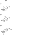
- FIG. 6 is a perspective view illustrating a configuration example of a projection provided on a lens pressing portion of a nozzle unit, where 6001 indicates a configuration of a plate-like rib illustrated in FIG. 5, and 6002 indicates a configuration example of a projection illustrated in 6001.
- 6003 show still another configuration example of the projection shown in 6001.
- FIG. 7A is a bottom view when viewed from below
- FIG. 7B is a cross-sectional view illustrating a cross section perpendicular to the front-rear direction.
- Numerals 8001 to 8005 each show a cross-sectional shape of a tapered inner wall surface forming the inner cavity of the nozzle portion.
- 9001 to 9005 are views each showing another cross-sectional shape of the tapered inner wall surface constituting the inner cavity of the nozzle portion.
- 10001 to 10005 are diagrams each showing another cross-sectional shape of the ridge portion formed on the tapered inner wall surface forming the inner cavity of the nozzle portion.
- the structure of the centering member attached to the annular expansion part is shown, 10001 is a perspective view, and 11002 is a sectional view.
- 12001 is a front view showing the configuration of the centering member as viewed from the front side
- 12002 is a cross-sectional view perpendicular to the front-rear direction showing the configuration of the centering member attached to the annular enlarged portion.
- FIG. 1 is a perspective view showing an entire configuration of an intraocular lens insertion device 1 (hereinafter, referred to as an insertion device 1).
- the insertion device 1 includes a cylindrical device main body 2, a distal tip 3, a lens holder 4 for holding an intraocular lens 7, a plunger 5, a lens presser 6, and a centering member. 8 and a spring 9.
- the tip 3 has a nozzle portion 32 connected to the apparatus main body 2.
- the lens holder 4 can be attached to the apparatus main body 2.
- the plunger 5 has a rod shape, and is configured to be inserted into the apparatus main body 2.
- the lens pressing portion 6 is provided behind the nozzle portion 32 in the tip 3.
- the centering member 8 is a member for positioning the center axis of the plunger 5 and is attached to the apparatus main body 2. Note that the lens holder 4 may be attached to the tip 3.
- the axial direction of the plunger 5 is defined as the front-back direction.
- the thickness direction of the intraocular lens 7 held by the lens holder 4 is defined as the up-down direction, and the direction perpendicular to both the front-rear direction and the up-down direction is defined as the left-right direction.
- the tip 3 side of the insertion device 1 is defined as a front side, and the opposite side is defined as a rear side.
- the lens pressing portion 6 side of the tip chip 3 is defined as an upper side, and the opposite side is defined as a lower side.
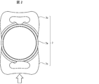
- FIG. 2 is a top view showing the configuration of the intraocular lens 7 mounted on the lens holder 4 of the insertion device 1.
- the intraocular lens 7 includes a lens portion 7a, a front support portion 7b, and a rear support portion 7c.
- the lens portion 7a is a lens portion that functions as a crystalline lens after insertion into the eye.
- the front support portion 7b and the rear support portion 7c have a function of supporting the lens portion 7a in the eye after insertion into the eye.
- the front support portion 7b and the rear support portion 7c are provided symmetrically with respect to the lens portion 7a, and have a flat plate shape.
- the front support portion 7b is formed so as to cover a front side surface of the lens portion 7a.
- the rear support portion 7c is formed so as to cover a rear side surface of the lens portion 7a.
- the intraocular lens 7 is a plate-type intraocular lens whose outer shape is substantially rectangular, and the rectangle is formed by a lens portion 7a, a front support portion 7b, and a rear support portion 7c.
- the lens portion 7a, the front support portion 7b, and the rear support portion 7c are made of a material having flexibility, and are formed to be flexibly deformable.
- a single piece type in which the lens portion 7a, the front support portion 7b, and the rear support portion 7c are integrally formed will be described as an example.
- the device main body 2 has a configuration in which the distal end tip 3 is engaged with the front, an annular enlarged portion 22 that can be gripped by an operator on the outer surface of the front end, and a flange that the operator holds by holding a finger on the outer surface of the rear end. And a holding portion 23 in a shape of a circle.
- the apparatus main body 2 is formed using a resin such as polycarbonate having impact resistance.
- the annular enlarged portion 22 is formed of, for example, a plurality of annular protrusions.
- the annular expanding portion 22 and the holding portion 23 may have any shape as long as they can perform required functions.
- the holding portion 23 may be formed by a protrusion or the like that allows a finger to be hooked, instead of a flange shape.
- the surgeon grasps the annular enlarged portion 22 with the other hand and holds the intraocular lens 7 in the order of the front support portion 7b, the lens portion 7a, and the rear support portion 7c. Release into the patient's eye.
- the provision of the annular enlarged portion 22 makes it easier for the surgeon to grasp the insertion instrument 1 and enhances the operability of the insertion instrument 1.
- the distal tip 3 has an emission portion 31 from which the intraocular lens 7 is emitted, a nozzle portion 32 whose inner diameter gradually decreases toward the front, and a rectangular portion 33 having a rectangular outer periphery with an open side surface. are doing.
- the distal tip 3 is connected to the device main body 2 by engaging the rectangular portion 33 with the device main body 2.
- a lens holding portion 6 is attached to the upper side near the entrance of the nozzle portion 32.
- the configuration for engaging the tip 3 with the apparatus main body 2 may be any configuration such as, for example, engagement between a locking claw and a locking hole.
- the tip 3 is formed using a resin such as polypropylene or polyamide having chemical resistance and flexibility.
- the insertion device 1 has a configuration in which the lens holder 4 holding the intraocular lens 7 can be attached.
- the insertion device 1 according to the present embodiment may have a form in which the lens holder 4 is separated or a form in which the lens holder 4 is attached.
- the surgeon inserts the lens holder 4 into the opening formed on the side surface of the rectangular portion 33.
- the rectangular part 33 can be said to be an installation part on which the lens holder 4 is installed. Note that the lens holder 4 may be inserted into the opening of the rectangular portion 33 before use of the insertion device 1, or may be inserted into the opening of the rectangular portion 33 when the insertion device 1 is used.
- the lens holder 4 has a housing part 41 that forms a housing space for housing the intraocular lens 7, and a knob part 42 provided to protrude laterally from the housing part 41.
- the accommodation section 41 has openings formed on both the front side and the rear side.
- the space inside the housing portion 41 and the space inside the nozzle portion 32 communicate with each other through an opening formed on the rear side of the housing portion 41.
- the operator grasps the knob 42 and inserts the lens holder 4 into an opening formed on the side surface of the rectangular portion 33, so that the intraocular lens 7 is inserted. 1 is attached.
- the lens holder 4 is formed using a resin such as polypropylene having chemical resistance.
- the plunger 5 includes a rear shaft portion 51, a pressing portion 52, and a center shaft portion 53.
- the rear side shaft portion 51 is located on the rearmost side of the plunger 5.
- the rear shaft portion 51 is a portion that is exposed to the outside when the plunger 5 is in the initial position where the plunger 5 is inserted into the apparatus main body 2.
- the rearward movement of the rear shaft 51 is restricted by a stopper provided at the rear end of the apparatus main body 2.
- the pressing portion 52 is formed in a flange shape on the peripheral surface on the rear side of the rear side shaft portion 51. The operator moves the plunger 5 toward the distal end by pushing the pressing portion 52 toward the apparatus main body 2.
- the center shaft 53 is connected to the front side of the rear shaft 51 and is a shaft having a smaller diameter than the rear shaft 51.
- a lens contact member 54 that contacts the rear support portion 7c of the intraocular lens 7 is attached to the distal end of the center shaft portion 53.
- the spring 9 is provided along the outer peripheral surface of the center shaft portion 53. Thereby, the reaction force is received from the spring 9 when the plunger 5 is pushed, and the intraocular lens 7 can be prevented from vigorously jumping out of the lens contact member 54 of the plunger 5.
- the position of the spring 9 is not particularly limited.
- the spring 9 may be disposed between the pressing portion 52 of the plunger 5 and the rear end of the apparatus main body 2, provided that the spring 9 receives a reaction force from the elastic member when the plunger 5 is pressed. Good.
- the plunger 5 When the plunger 5 is pushed from the initial position to the front-back direction from the initial position in a state where the plunger 5 is at the initial position, the plunger 5 passes through the opening formed on the rear side of the housing portion 41. Then, the lens contact member 54 at the tip of the plunger 5 comes into contact with the rear support portion 7c of the intraocular lens 7. Then, the plunger 5 further advances to the distal end side, passes through an opening formed in the front side of the housing section 41, and advances into the distal end tip 3. At this time, the intraocular lens 7 is folded in a concave shape while passing through the nozzle portion 32 of the tip 3. Next, the intraocular lens 7 reaches the emission unit 31 in a state where the intraocular lens 7 is folded. The intraocular lens 7 that has reached the emission unit 31 is inserted into the eye from the cut side of the emission unit 31 in the order of the front support unit 7b, the lens unit 7a, and the rear support unit 7c.
- a front support portion and a rear support portion are formed so as to extend in a curved manner from the side surface of the lens portion. It has a loop shape.
- the intraocular lens 7, which is the above-mentioned plate-type intraocular lens, is made of a material having flexibility as compared with the intraocular lens having the loop-shaped front support portion and the rear support portion. Therefore, when a plate-type intraocular lens 7 is inserted into the eye using a conventional intraocular lens insertion device equipped with an intraocular lens, the intraocular lens 7 may be damaged.
- An object of the insertion device 1 according to the present embodiment is to appropriately insert a plate-type intraocular lens 7 made of a flexible material into an eye without damaging the intraocular lens 7.
- the contact position of the plunger 5 in the intraocular lens 7 may deviate from the original contact position due to a mounting error of the intraocular lens 7 with respect to the lens holder 4 or the like. For this reason, there is a possibility that the plunger 5 rides on or slips into the intraocular lens 7.
- the intraocular lens 7 is made of a flexible material. Therefore, the intraocular lens 7 may be damaged and damaged by the plunger 5.
- the intraocular lens 7 is made of a flexible material, the intraocular lens 7 is easily deformed rearward from the contact position of the plunger 5 by the pushing operation by the plunger 5.
- a force for moving the intraocular lens 7 in a contact portion with the plunger 5 acts forward.
- a force remaining on the tapered surface of the nozzle portion 32 acts on the portion other than the contact portion due to friction with the tapered surface of the nozzle portion 32.
- the intraocular lens 7 passes through the nozzle portion 32 in a state where it is excessively extended rearward from the contact position with the plunger 5, and the intraocular lens 7 may be damaged.
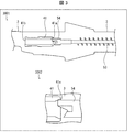
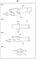
- FIG. 4 is a cross-sectional view showing a state when the lens contact member 54 of the plunger 5 has reached the opening 41a on the rear side of the accommodating portion 41, and 3002 in FIG. 3 is an enlarged view of 3001 in FIG. It is. 4 shows a configuration of the lens contact member 54, 4001 in FIG. 4 is a perspective view, 4002 in FIG. 4 is a top view, 4003 in FIG. 4 is a side view, and 4004 in FIG. Is a front view seen from the front side.
- the lens contact member 54 of the plunger 5 that contacts the intraocular lens 7 is made of an elastically deformable material that is softer than the central shaft portion 53 of the plunger 5 and that can be elastically deformed. Have been. Further, as the material forming the lens contact member 54, for example, silicone, silicone elastomer, or the like can be used.
- the lens contact member 54 is provided with a projection 54a protruding from the lateral side in the left-right direction.
- the lens abutting member 54 has an alligator-shaped crocodile structure 54b cut out larger than the vertical dimension (thickness direction) of the intraocular lens 7.
- the crocodile mouth structure 54b has a structure in which the intraocular lens 7 is vertically sandwiched at least in the housing portion 41 of the lens holder 4, and an upper slope portion 54c and a lower slope portion 54d that face each other in the vertical direction. Have.
- the lower slope portion 54d is formed of an inclined surface connected to the lower surface 54e of the lens contact member 54.
- no surface perpendicular to the lower surface 54e is interposed between the inclined surface of the lower slope portion 54d and the lower surface 54e.
- the structure of the “slope surface connected to the lower surface 54e of the lens contact member 54” here refers to the accuracy of the processing condition during the processing of the connection structure between the lower surface 54e and the slope surface of the lower slope portion 54d.
- a structure in which an R surface or the like is formed at a connection portion between the inclined surface of the lower slope portion 54d and the lower surface 54e is also included.
- the vertical dimension of the lens contact member 54 is greater than or equal to the vertical dimension of the rear opening 41a and the front opening 41b of the housing 41. More specifically, the vertical dimension of the lens contact member 54 is greater than or equal to the distance between the walls of the housing 41 that are opposed to each other in the vertical direction. Accordingly, when the lens contact member 54 is inserted into the housing portion 41, the lens abutment member 54 is elastically deformed so as to fit within the space between the vertically opposed walls of the housing portion 41. Then, due to this elastic deformation, the upper slope portion 54c and the lower slope portion 54d of the alligator structure 54b are elastically deformed so as to reduce the interval therebetween, and come into contact with the upper and lower surfaces of the intraocular lens 7.
- the intraocular lens 7 housed in the housing part 41 is sandwiched by the alligator structure 54b. Therefore, even if the mounting error of the intraocular lens 7 with respect to the lens holder 4 occurs, the displacement of the contact position of the plunger 5 in the intraocular lens 7 is eliminated. Therefore, according to the insertion device 1 according to the present embodiment, it is possible to prevent the plunger 5 from climbing onto the intraocular lens 7 or getting into the intraocular lens 7.
- the upper limit of the vertical dimension of the lens contact member 54 is such that the movement of the lens contact member 54 is hindered by the contact between the lens contact member 54 and the walls of the accommodating portion 41, the nozzle portion 32, and the discharge portion 31.
- the range can be set as appropriate depending on the material of the lens contact member 54, the dimensions of the alligator structure 54b, and the like, within a range not present.
- the lower slope portion 54d is formed of an inclined surface connected to the lower surface 54e of the lens contact member 54. Therefore, when the plunger 5 moves forward while the lens contact member 54 is in contact with the intraocular lens 7, the rear support portion 7c of the intraocular lens 7 moves on the lower slope portion 54d, and is smooth. In addition, the intraocular lens 7 easily fits in the crocodile mouth structure 54b. Therefore, the intraocular lens 7 can be more reliably held by the alligator structure 54b.
- the vertical dimension of the lens contact member 54 is preferably the distance between the vertically opposed walls that form the lumens of the discharge part 31 and the nozzle part 32 of the tip 3. Greater than or the same.
- the projection 54a of the lens contact member 54 functions as a stopper that restricts the extension and deformation of the intraocular lens 7 to the rear side.
- the extension deformation of the intraocular lens 7 toward the rear side can be said to be extension deformation of the intraocular lens 7 in the direction opposite to the pushing direction of the plunger 5.
- the intraocular lens 7 When the intraocular lens 7 is pushed into the tapered nozzle portion 32 and folded, a portion that is deformed rearward from the contact position with the plunger 5 is formed by a protrusion 54 a provided on the side surface of the lens contact member 54. Locked. Therefore, the deformation of the intraocular lens 7 from the contact position with the plunger 5 to the rear side is restricted by the projection 54a, and it is possible to prevent the intraocular lens 7 from passing through the nozzle portion 32 in an excessively extended state. Therefore, according to the insertion device 1 according to the present embodiment, the extension of the intraocular lens 7 in the nozzle portion 32 toward the rear side can be suppressed, and the intraocular lens 7 can be prevented from being damaged. .
- the size of the lens contact member 54 in the left-right direction is within a range in which the movement of the lens contact member 54 is not hindered by the contact between the lens contact member 54 and the walls of the accommodating portion 41, the nozzle 32, and the discharge portion 31.
- it can be appropriately set according to the material of the lens contact member 54, the size of the protrusion 54a, and the like.
- FIG. 6 shows the lens pressing part 6 attached to the nozzle part 32
- 7001 in FIG. 7 is a bottom view seen from below
- 7002 in FIG. 7 is a cross-sectional view showing a cross section perpendicular to the front-rear direction. It is.
- the lens pressing portion 6 includes a plate-shaped rib portion 61 (projection portion) and a base portion 62 that supports the plate-shaped rib portion 61. , A shaft portion 63 and a leaf spring portion 64.
- the rotating mechanism of the plate-shaped rib portion 61 in the insertion device 1 has a configuration including at least the shaft portion 63 and the plate spring portion 64.
- the plate-shaped rib portion 61 is a protruding ridge protruding toward the lumen side of the nozzle portion 32 and extending in the front-rear direction (the pushing direction of the plunger 5) over a predetermined dimension.
- the lower end portion of the plate-shaped rib portion 61 is formed such that its shape is a downwardly convex single curve in the front-rear direction. Further, the plate-shaped rib portion 61 is arranged so as to abut on the plunger 5 and to contact at least the lens portion 7a of the intraocular lens 7 at the lower end.
- the shaft 63 is provided so as to protrude from the base 62 in the left-right direction, and is inserted into a bearing opening provided in the nozzle 32.
- the lens pressing part 6 is connected to the nozzle part 32 via a shaft part 63, and is rotatable around the shaft part 63 extending in the left-right direction.
- the leaf spring portion 64 has a plate shape bent in a forward convex shape, and is provided in contact with a predetermined plane of the nozzle portion 32.
- the leaf spring portion 64 is configured to bias the base portion 62 so that the base portion 62 rotates in a direction approaching the nozzle portion 32. Therefore, when the base 62 rotates about the shaft 63 in the direction away from the nozzle 32, the leaf spring 64 applies an urging force to the base 62 so as to move closer to the nozzle 32. .
- the central portion of the lens portion 7a of the intraocular lens 7 is in contact with the plate-like rib portion 61.
- the central portion of the intraocular lens 7 is positioned by the plate-shaped rib portion 61 near the entrance of the nozzle portion 32.
- the intraocular lens 7 is moved forward by the pushing operation of the plunger 5 in such a positioned state, the intraocular lens 7 is folded by the tapered surface of the nozzle portion 32 without a positional shift of the central portion. .
- the intraocular lens 7 that has passed through the lens holding portion 6 and moved forward is folded in a valley-folded state that is line-symmetric with respect to the center portion and convex toward the bottom surface of the nozzle portion 32. become.
- the plunger 5 is pushed into the nozzle part 32 in a state where the lens contact member 54 at the tip is in contact with the rear end of the intraocular lens 7. For this reason, when the intraocular lens 7 moves forward through the lens pressing portion 6, the lens surface of the intraocular lens 7 comes into contact with the plate-shaped rib portion 61 of the lens pressing portion 6. State, a state in which the lens contact member 54 is in contact with the plate-shaped rib portion 61 of the lens pressing portion 6, or a state in which the lens surface of the intraocular lens 7 and the lens contact member 54 are in contact with the plate-shaped rib portion 61 of the lens pressing portion 6. Both are in contact.
- the pressing force of the plunger 5 causes the plate-like rib portion 61 to pivot about the shaft portion 63 in a direction in which the lower end portion moves away from the bottom surface of the nozzle portion 32. And does not hinder the progress of the plunger 5.
- the lens surface of the intraocular lens 7 is in contact with the plate-shaped rib portion 61 of the lens pressing portion 6, the lens that moves forward when the plunger 5 is further pushed forward.
- the plate-shaped rib portion 61 may be rotated by the contact action between the surface and the lens pressing portion 6. That is, the plate-shaped rib 61 may rotate before the lens contact member 54 comes into contact with the plate-shaped rib 61.
- the plate-shaped rib portion 61 is moved by the urging force of the plate spring portion 64. It rotates in the direction approaching the bottom. Then, the lens holding unit 6 is returned to the initial position.
- the intraocular lens 7 is folded line-symmetrically and valley-folded with the central portion positioned by the plate-shaped rib portion 61. Therefore, the plate-type intraocular lens 7 is released from the release unit 31 without being damaged by the pushing operation by the plunger 5.
- the plate-shaped rib portion 61 is rotated in the pushing direction of the plunger 5 by the contact with the plunger 5 by the rotating mechanism including the shaft portion 63 and the plate spring portion 64. For this reason, even after the intraocular lens 7 has passed through the lens holder 6, the movement of the plunger 5 is not hindered by the lens holder 6. Therefore, the plunger 5 can be smoothly pushed in while the intraocular lens 7 is folded in a symmetrically trough manner at the nozzle portion 32.
- the protrusion extending in the front-rear direction protrudes toward the lumen side of the nozzle portion 32, and may have any configuration that positions the central portion of the intraocular lens 7 as described above.
- the present invention is not limited to the plate-like rib portion 21 shown in FIG.
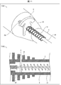
- FIG. 6 is a perspective view showing an example of the configuration of the protruding portion.
- reference numeral 6001 denotes a configuration of the plate-like rib portion 61 shown in FIG. 5
- reference numeral 6002 in FIG. 6 and reference numeral 6003 in FIG. 6 shows still another configuration example of the projection shown in 6001 in FIG.
- two plate-shaped rib portions 61 are provided.
- the two plate-shaped ribs 61 protrude from the base 62 toward the lumen side of the nozzle portion 32 and extend in the front-rear direction (the direction in which the plunger 5 is pushed out) over a predetermined dimension so as to be parallel to each other. Further, the two plate-shaped rib portions 61 are arranged so as to be line-symmetric with respect to the symmetry axis of the nozzle portion 32.
- the number of the protrusions is not limited to two, such as the plate-like rib 61 shown in 6001 of FIG. As shown by 6002 in FIG. 6, the protrusion 61 a may be a single ridge protruding from the base 62 to the lumen side of the nozzle 32.
- the protrusion 61a has a width in the left-right direction such that the central portion of the intraocular lens 7 is positioned.
- the projection 61a shown by 6002 in FIG. 6 is solid.
- the protrusion is not limited to a solid structure, and may have a hollow structure.
- Reference numeral 6003 in FIG. 6 illustrates a configuration example of the protrusion 61b having a hollow structure.
- the protrusion 61b is formed as a concave groove that is recessed from the base 62a toward the lumen side of the nozzle portion 32.
- the protrusion 61b extends in the front-rear direction (extending direction of the plunger 5) over a predetermined dimension.
- the protrusion 61b has a width in the left-right direction such that the central portion of the intraocular lens 7 is positioned.
- the insertion device 1 is characterized by the shape of the tapered inner wall surface that forms the lumen of the nozzle part 32 because the intraocular lens 7 is folded line-symmetrically and folded in the nozzle part 32.
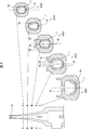
- 8001 to 8005 are views each showing a cross-sectional shape of the tapered inner wall surface 35 constituting the lumen 34 of the nozzle portion 32.
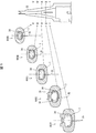
- Each of 9001 to 9005 in FIG. 9 is a diagram showing another cross-sectional shape of the tapered inner wall surface 35 forming the lumen 34 of the nozzle portion 32.
- the cross-sectional shapes perpendicular to the front-rear direction are, in order from the rear side to the front side, the II line cross-sectional shape, the II-II line cross-sectional shape, the III-III line cross-sectional shape, and the IV-
- the IV line cross-sectional shape and the VV line cross-sectional shape correspond to the cross-sectional shapes 8001 and 9001 to 8005 and 9005, respectively.
- the nozzle portion 32 includes a lumen 34, a tapered inner wall surface 35 forming the lumen 34, and a ridge 36.
- the ridge 36 is provided on the tapered inner wall surface 35 on the upper side, and protrudes downward.
- two convex ridges 36 are provided with a vertical axis of symmetry of the nozzle 32 interposed therebetween. These two ridges 36 are arranged to be line-symmetric with respect to the axis of symmetry of the nozzle 32.
- the protruding ridge portion 36 is provided so as to avoid at least the tip portion of the nozzle portion 32.
- the intraocular lens 7 moved to the nozzle portion 32 by the pushing operation of the plunger 5 is folded valley by the lens pressing portion 6 near the position and opening of the nozzle portion 32 and moves forward. Then, the valley-folded intraocular lens 7 moves forward while being folded by the action of the tapered inner wall surface 35.
- the traveling axis of the intraocular lens 7 may be shifted.
- the intraocular lens 7 whose traveling axis is displaced in this way rotates and moves along the tapered inner wall surface 35. As a result, there is a possibility that the intraocular lens 7 will not be folded due to the line-symmetric valley fold.
- the rotational movement of the intraocular lens 7 along the tapered inner wall surface 35 is restricted by the provision of the ridge 36 on the nozzle 32.
- the valley-folded intraocular lens 7 is moved forward by the plunger 5
- the left-right end of the intraocular lens 7 is formed on the tapered inner wall surface 35.
- the movement along is locked by the ridge 36.
- the locking of the end portion of the intraocular lens 7 by the convex ridge portion 36 is released in the vicinity of the tip end of the nozzle portion 32 where the convex ridge portion 36 is not provided.
- the intraocular lens 7 is folded line-symmetrically and valley-folded in the nozzle portion 32.
- the protruding ridge portion 36 is provided on the rear side of the front end of the lens pressing portion 6. Is preferred. In the vicinity of the inlet of the nozzle portion 32, the convex portion 36 does not necessarily need to be provided on the rear side of the lens pressing portion 6. The reason is that the left and right ends of the intraocular lens 7 do not reach the position of the convex portion 36 of the tapered inner wall surface 35 near the entrance of the nozzle portion 32.
- the cross-sectional shapes 8001 to 8005 of the tapered inner wall surface 35 forming the inner cavity 34 of the nozzle portion 32, which are perpendicular to the front-rear direction, are vertically long in the vertical direction.
- the cross-sectional shape of the tapered inner wall surface 35 can be appropriately set according to the dimensions of the intraocular lens 7, folding behavior, and the like, and is not limited to the cross-sectional shapes 8001 to 8005 shown in FIG.
- the cross-sectional shape of the tapered inner wall surface 35 may be cross-sectional shapes 9001 to 9005 horizontally long in the left-right direction as shown in FIG.
- the number of the ridges 36 is not particularly limited as long as the number is arranged symmetrically with respect to the axis of symmetry of the nozzle 32.
- a configuration provided with one protruding ridge portion 36a such as the cross-sectional shapes 10001 to 10005 shown in FIG. 10, may be used.
- the protruding ridge portion 36 a has a shape symmetrical with respect to the axis of symmetry of the nozzle portion 32, and is provided so as to avoid at least the tip portion of the nozzle portion 32.
- the nozzle portion 36a has a shape such that the width in the left-right direction decreases toward the tip end side of the nozzle portion 32. Even in the cross-sectional shapes 10001 to 10005 shown in FIG. 10, the intraocular lens 7 is folded line-symmetrically and valley in the nozzle portion 32.
- the centering member 8 is a member that restricts such rattling of the plunger 5.
- FIG. 11 shows the configuration of the centering member 8 attached to the annular enlarged portion 22
- 11011 in FIG. 11 is a perspective view
- 11002 in FIG. 11 is a sectional view
- 12 is a front view showing the configuration of the centering member 8 as viewed from the front side
- 12002 in FIG. 12 shows the configuration of the centering member 8 attached to the annular enlarged portion 22 and is perpendicular to the front-rear direction.
- the centering member 8 is provided on the annular enlarged portion 22 of the apparatus main body 2.
- the position of the centering member 8 in the apparatus main body 2 is not limited to the annular enlarged portion 22.
- the plunger 5 is attached to the centering member 8 such that the lens contact member 54 is located on the front side.
- the spring 9 is arranged on the rear side of the centering member 8. With such a configuration, the lens contact member 54 of the plunger 5 moves only forward of the centering member 8 and does not move rearward.
- the annular enlarged portion 22 is composed of a plurality of annular protrusions
- the centering member 8 is provided between the annular protrusions, as shown by 11002 in FIG.
- the centering member 8 has two lower locking claws 81, a plunger insertion portion 82, and an upper locking piece 83.
- the plunger insertion portion 82 is provided between the lower locking claw 81 and the upper locking piece 83, and the center shaft portion 53 of the plunger 5 is inserted.
- a through-hole through which the plunger insertion portion 82 can vertically penetrate is provided above the annular enlarged portion 22. Further, two through holes through which the lower locking claw 81 can penetrate are provided below the annular enlarged portion 22.
- the lower locking claw 81 penetrates through two through holes provided below the annular enlarged portion 22 and is locked by being hooked on the through hole from outside the annular enlarged portion 22.
- the upper locking piece 83 is abutted and locked from the outside to the edge of the upper through hole of the annular enlarged portion 22 through which the plunger insertion portion 82 penetrates.
- the lower locking claw 81 and the upper locking piece 83 are locked to the annular enlarged portion 22, so that the plunger insertion portion 82 is aligned with the advancing axis of the plunger 5. Therefore, when the plunger 5 is inserted into the plunger insertion portion 82, rattling in the left-right direction and the up-down direction is regulated even when a force is applied.
- the contact position of the plunger 5 in the intraocular lens 7 does not deviate from the advancing axis of the intraocular lens 7.
- the centering member 8 may be separate from the apparatus main body 2 or may be formed integrally with the apparatus main body 2.
- An intraocular lens insertion device is an intraocular lens insertion device to which a lens holder that holds an intraocular lens can be attached, wherein the intraocular lens insertion device abuts on the intraocular lens held by the lens holder.
- a distal end portion, and the distal end portion includes a stopper that regulates extension deformation of the intraocular lens in a direction opposite to a pushing direction of the plunger.
- the stopper is a projection provided on a side surface of the distal end portion.
- An intraocular lens insertion device is the intraocular lens insertion device according to aspect 1 or 2, wherein the distal end portion has a U-shaped crocodile mouth structure that sandwiches the intraocular lens in a thickness direction. Is preferred.
- the intraocular lens insertion device is the intraocular lens insertion tool according to aspect 3, wherein the crocodile mouth structure has a lower slope portion and an upper slope portion that face each other in a thickness direction of the intraocular lens, It is preferable that the lower slope portion is constituted by an inclined surface connected to a lower surface of the tip portion.
- An intraocular lens insertion device is an intraocular lens insertion device to which a lens holder that holds an intraocular lens can be attached, wherein the intraocular lens insertion device abuts on the intraocular lens held by the lens holder.
- a plate-shaped rib portion extending in a direction, and a rotating mechanism for rotating the plate-shaped rib portion in the pushing direction by abutting the plate-shaped rib portion with a lens surface of the intraocular lens and / or the plunger. , Is provided.
- An intraocular lens insertion device is an intraocular lens insertion device to which a lens holder that holds an intraocular lens can be attached, wherein the intraocular lens insertion device abuts on the intraocular lens held by the lens holder.
- the protrusion is a plate-like rib protruding toward a lumen side of the nozzle portion and extending in a pushing direction of the plunger.
- An intraocular lens insertion device is an intraocular lens insertion device to which a lens holder that holds an intraocular lens can be attached, wherein the intraocular lens insertion device abuts on the intraocular lens held by the lens holder.
- the ridge portion is disposed so as to be symmetric with respect to an axis of the nozzle portion, and at least avoids a tip portion of the nozzle portion. It is preferable that the configuration is provided.
- the intraocular lens insertion device according to aspect 10 of the present invention is preferably configured such that, in aspect 9, at least two of the ridges are arranged symmetrically with respect to the axis of the nozzle portion. .
- An intraocular lens insertion device is an intraocular lens insertion device including a cylindrical main body, and capable of attaching a lens holder holding an intraocular lens to an end surface side of the main body, wherein the lens A plunger which is inserted into and retracted from the main body in order to push the intraocular lens in contact with the intraocular lens held by the holder, and the intraocular lens while folding the intraocular lens extruded by the plunger And a nozzle portion for discharging the fluid, wherein the main body is provided with a centering member for centering the plunger.
- An intraocular lens insertion device is the intraocular lens insertion device according to any one of aspects 5 to 7, wherein the rotating mechanism is provided with a shaft protruding left and right from a base supporting the plate-shaped rib. And a plate spring for urging the base so that the base rotates in a direction approaching the nozzle.
- Intraocular lens insertion device 2 Apparatus main body 3 Tip tip 4 Lens holder 5 Plunger 7 Intraocular lens 8 Centering member 22 Annular enlarged portion 32 Nozzle portion 35 Tapered inner wall surface 36, 36a Convex ridge 41 Housing 41a, 41b Opening 54 Lens contact member 54a Projection ( Stopper) 54b Alligator structure 54c Upper slope 54d Lower slope 54e Lower surface 61 Plate-shaped rib (projection) 62 Base 63 Shaft 64 Plate spring 81 Lower locking claw 82 Plunger insertion part 83 Upper locking piece
Landscapes
- Health & Medical Sciences (AREA)
- Ophthalmology & Optometry (AREA)
- Cardiology (AREA)
- Oral & Maxillofacial Surgery (AREA)
- Transplantation (AREA)
- Engineering & Computer Science (AREA)
- Biomedical Technology (AREA)
- Heart & Thoracic Surgery (AREA)
- Vascular Medicine (AREA)
- Life Sciences & Earth Sciences (AREA)
- Animal Behavior & Ethology (AREA)
- General Health & Medical Sciences (AREA)
- Public Health (AREA)
- Veterinary Medicine (AREA)
- Prostheses (AREA)
Abstract
柔軟性素材で構成されたプレート型の眼内レンズを破損することなく、適切に眼内に挿入することを目的として、本発明では、挿入器具(1)において、プランジャ(5)は、眼内レンズ(7)と当接する、弾性変形材料で構成されたレンズ当接部材(54)を備え、レンズ当接部材(54)は、プランジャ(5)の押出方向と反対方向への眼内レンズ(7)の伸び変形を規制する突起(54a)を備えている。
Description
本発明は、眼内レンズ挿入器具に関する。
レンズホルダに保持された眼内レンズをプランジャによって押し出して放出する眼内レンズ挿入器具が従来技術として知られている(例えば特許文献1~3)。特許文献1~3に記載の眼内レンズ挿入器具は、プランジャの押込み動作によって、レンズホルダに保持された眼内レンズを凹状に折り畳みつつ眼内レンズを放出するノズル部を備えている。このノズル部は、前方へ行くに従い内径が徐々に小さくなる構成となっている。
特許文献1~3に開示された従来の眼内レンズ挿入器具に搭載される眼内レンズは、レンズ部と、前方支持部と、後方支持部とを備えている。そして、前方支持部及び後方支持部が、レンズ部側面から曲線状に延び出るように形成されたループ形状を有している。
市販されている眼内レンズには、上述したループ形状の前方支持部及び後方支持部を有するレンズ以外に、外形形状が略矩形であるプレート型眼内レンズがある。プレート型眼内レンズは、ループ形状の前方支持部及び後方支持部を有する眼内レンズと比較して、柔軟性を有する素材で構成されて場合が多い。それゆえ、特許文献1~3に開示された眼内レンズ挿入器具を使用してプレート型の眼内レンズを眼内で挿入した場合、眼内レンズが破損するおそれがある。
本発明の一態様は、柔軟性素材で構成されたプレート型の眼内レンズを破損することなく、適切に眼内に挿入することが可能な眼内レンズ挿入器具を実現することを目的とする。
上記の課題を解決するために、本発明の一態様に係る眼内レンズ挿入器具は、眼内レンズを保持するレンズホルダを取り付け可能な眼内レンズ挿入器具であって、前記レンズホルダに保持された眼内レンズに当接して前記眼内レンズを押出すプランジャと、前記プランジャにより押出された眼内レンズを折り畳みつつ外部へ放出するノズル部と、を備え、前記プランジャは、前記眼内レンズと当接する、弾性変形材料で構成された先端部を備え、前記先端部は、前記プランジャの押出方向と反対方向への前記眼内レンズの伸び変形を規制するストッパを備えたことを特徴としている。
上記の課題を解決するために、本発明の一態様に係る眼内レンズ挿入器具は、眼内レンズを保持するレンズホルダを取り付け可能な眼内レンズ挿入器具であって、前記レンズホルダに保持された眼内レンズに当接して前記眼内レンズを押出すプランジャと、前記プランジャにより押出された眼内レンズを折り畳みつつ外部へ放出するノズル部と、を備え、前記ノズル部は、当該ノズル部の中央に設けられ、前記プランジャの押出方向へ延びる板状リブ部と、前記板状リブ部と前記眼内レンズのレンズ面との当接、前記板状リブ部と前記プランジャとの当接、又は前記板状リブ部と前記眼内レンズのレンズ面及び前記プランジャの両方との当接により、前記板状リブ部を前記押出方向へ回動させる回動機構と、を備えたことを特徴としている。
上記の課題を解決するために、本発明の一態様に係る眼内レンズ挿入器具は、眼内レンズを保持するレンズホルダを取り付け可能な眼内レンズ挿入器具であって、前記レンズホルダに保持された眼内レンズに当接して前記眼内レンズを押出すプランジャと、前記プランジャにより押出された眼内レンズを折り畳みつつ外部へ放出するノズル部と、を備え、前記ノズル部は、当該ノズル部の中央に設けられ、前記ノズル部の内腔側へ突出し前記プランジャの押出方向へ延びる突起部と、前記突起部と前記眼内レンズのレンズ面との当接、前記突起部と前記プランジャとの当接、又は前記突起部と前記眼内レンズのレンズ面及び前記プランジャの両方との当接により、前記突起部を前記押出方向へ回動させる回動機構と、を備えたことを特徴としている。
上記の課題を解決するために、本発明の一態様に係る眼内レンズ挿入器具は、眼内レンズを保持するレンズホルダを取り付け可能な眼内レンズ挿入器具であって、前記レンズホルダに保持された眼内レンズに当接して前記眼内レンズを押出すプランジャと、前記プランジャにより押出された眼内レンズを折り畳みつつ外部へ放出するノズル部と、を備え、前記ノズル部は、前記プランジャの押出方向へ向かうに従い対向する壁面同士の間隔が小さくなったテーパー内壁面を有し、前記テーパー内壁面には、当該テーパー内壁面に沿った前記眼内レンズの回転移動を規制する、前記押出方向へ延びる凸条部が形成されていることを特徴としている。
上記の課題を解決するために、本発明の一態様に係る眼内レンズ挿入器具は、筒状の本体を備え、前記本体の端面側に眼内レンズを保持するレンズホルダを取り付け可能な眼内レンズ挿入器具であって、前記レンズホルダに保持された眼内レンズに当接して前記眼内レンズを押出すために前記本体に出退可能に内挿されるプランジャと、前記プランジャにより押し出された眼内レンズを折り畳みつつ前記眼内レンズを放出するノズル部と、を備え、前記本体には、前記プランジャをセンタリングするためのセンタリング部材が設けられていることを特徴としている。
本発明の一態様によれば、柔軟性素材で構成されたプレート型の眼内レンズを破損することなく、適切に眼内に挿入することが可能な眼内レンズ挿入器具を実現できる。
以下、本発明の一実施形態について、詳細に説明する。図1は、眼内レンズ挿入器具1(以下、挿入器具1と記す)の全体構成を示す斜視図である。図1に示されるように、挿入器具1は、筒状の装置本体2と、先端チップ3と、眼内レンズ7を保持するレンズホルダ4と、プランジャ5と、レンズ押え部6と、センタリング部材8と、スプリング9と、を備えている。先端チップ3は、装置本体2に接続されるノズル部32を有している。また、レンズホルダ4は、装置本体2に取り付け可能となっている。また、プランジャ5は、棒状であり、装置本体2に内挿される構成となっている。レンズ押え部6は、先端チップ3におけるノズル部32の後方に設けられている。また、センタリング部材8は、プランジャ5の中心軸を位置決めするための部材であり、装置本体2に取り付けられている。なお、レンズホルダ4は、先端チップ3に取り付けられていてもよい。
なお、ここでは、プランジャ5の軸芯方向を前後方向とする。また、レンズホルダ4に保持された眼内レンズ7の厚さ方向を上下方向とし、前後方向及び上下方向の両方に垂直な方向を左右方向とする。また、挿入器具1の先端チップ3側を前方側とし、その反対側を後方側とする。また、先端チップ3におけるレンズ押え部6側を上方側とし、その反対側を下方側とする。
図2は、挿入器具1のレンズホルダ4に搭載される眼内レンズ7の構成を示す上面図である。図2に示されるように、眼内レンズ7は、レンズ部7aと、前方支持部7bと、後方支持部7cとを備えている。レンズ部7aは、眼内挿入後に水晶体として機能するレンズ部分である。前方支持部7bおよび後方支持部7cは、眼内挿入後にレンズ部7aを眼内で支持する機能を有する。前方支持部7bおよび後方支持部7cは、レンズ部7aに対して対称に設けられており、偏平な板形状である。前方支持部7bは、レンズ部7aの前方の側面を覆うように形成されている。また、後方支持部7cは、レンズ部7aの後方の側面を覆うように形成されている。眼内レンズ7は、外形形状が略矩形であるプレート型眼内レンズであり、当該矩形は、レンズ部7a、前方支持部7b、後方支持部7cにより形成される。これらレンズ部7a、前方支持部7b、及び後方支持部7cは、柔軟性を有する材質であり、可撓変形可能に形成されている。本実施形態では、レンズ部7a、前方支持部7b及び後方支持部7cが一体的に成形されたシングルピース型を一例として説明する。
装置本体2は、前方に先端チップ3が係合される構成であり、前端の外面に術者が把持可能な環状拡大部22と、後端の外面に術者が指を掛けて保持する鍔状の保持部23とを有している。装置本体2は、耐衝撃性を有するポリカーボネート等の樹脂を用いて形成される。環状拡大部22は、例えば、複数の環状突起で構成されている。
なお、環状拡大部22及び保持部23は、必要とされる機能を発揮できるものであれば、どのような形状であってもよい。例えば、保持部23を鍔状ではなく指を掛けることが可能な突起等により構成してもよい。
術者は、片方の手でプランジャ5を押し込みながら、もう片方の手で環状拡大部22を把持して、眼内レンズ7を前方支持部7b、レンズ部7a、後方支持部7cの順番で、患者の眼内に放出する。環状拡大部22を設けることにより、術者が挿入器具1を把持し易くなり、挿入器具1の操作性を高めることができる。
先端チップ3は、眼内レンズ7が放出される放出部31と、前方へ向かうに従い内径が徐々に小さくなるノズル部32と、側面が開口された矩形の外周を有する矩形部33と、を有している。矩形部33を装置本体2に係合させることにより、先端チップ3は装置本体2に接続される。また、ノズル部32の入り口近傍の上側には、レンズ押え部6が取り付けられている。なお、先端チップ3と装置本体2とを係合する構成は、例えば、係止爪と係止穴とによる係合など、どのような構成であってもよい。また、先端チップ3は、耐薬品性や柔軟性のあるポリプロピレンやポリアミドなどの樹脂を用いて形成される。
挿入器具1は、眼内レンズ7を保持するレンズホルダ4を取り付け可能な構成である。本実施形態に係る挿入器具1は、レンズホルダ4が分離された形態であってもよいし、レンズホルダ4が取り付けられた形態であってもよい。挿入器具1の使用時には、術者は、矩形部33の側面に形成された開口にレンズホルダ4を挿入する。矩形部33は、レンズホルダ4を設置する設置部であるといえる。なお、レンズホルダ4は、挿入器具1の使用前に、予め矩形部33の開口に挿入されていてもよいし、挿入器具1の使用時に矩形部33の開口に挿入されてもよい。
レンズホルダ4は、眼内レンズ7を収容する収容空間を構成する収容部41と、収容部41から側方へ突出して設けられた摘み部42と、を有する。収容部41には、前方側および後方側の両方に開口部が形成されている。そして、収容部41の後方側に形成された開口部を介して収容部41内部の空間とノズル部32内の空間とが連通するようになっている。収容部41に眼内レンズ7を収容した後、術者が摘み部42を摘んで、レンズホルダ4を矩形部33の側面に形成された開口に挿入することにより、眼内レンズ7が挿入器具1に装着される。レンズホルダ4は、耐薬品性のあるポリプロピレンなどの樹脂を用いて形成される。
プランジャ5は、後方側軸部51と、押圧部52と、中軸部53と、を備えている。後方側軸部51は、プランジャ5の最も後方側に位置する。後方側軸部51は、プランジャ5が装置本体2に挿入された初期位置にある状態では外部に露出している部分である。また、後方側軸部51は、装置本体2の後端に設けられたストッパにより、後方への移動が制限されている。押圧部52は、後方側軸部51の後方側の周面に鍔状に形成される。術者は、この押圧部52を装置本体2側に押し込むことにより、プランジャ5を先端側に移動させる。
中軸部53は、後方側軸部51の前方側に接続され、後方側軸部51よりも細い径の軸部である。中軸部53の先端には、眼内レンズ7の後方支持部7cに当接するレンズ当接部材54が取り付けられている。
また、中軸部53の外周面に沿ってスプリング9が設けられている。これにより、プランジャ5の押込み時にスプリング9から反力を受け、眼内レンズ7がプランジャ5のレンズ当接部材54から勢いよく飛び出すことを防止できる。スプリング9の位置は特に限定されず、例えばプランジャ5の押圧部52と装置本体2の後端との間に配置してもよく、プランジャ5の押込み時に弾性部材から反力を受ける構成であればよい。
プランジャ5が初期位置にある状態で、術者によってプランジャ5が初期位置から前後方向の先端側に押し込まれると、プランジャ5は、収容部41の後方側に形成された開口部を通過する。そして、プランジャ5の先端にあるレンズ当接部材54が眼内レンズ7の後方支持部7cに当接した状態となる。そして、プランジャ5が更に先端側に進み、収容部41の前方側に形成された開口部を通過し先端チップ3内へ進む。このとき、眼内レンズ7は先端チップ3のノズル部32を通過しながら凹状に折り畳まれる。次いで、眼内レンズ7が折り畳まれた状態で、眼内レンズ7が放出部31に到達する。放出部31に到達した眼内レンズ7は、前方支持部7b、レンズ部7a、後方支持部7cの順番で放出部31のカットされている側から眼内に挿入される。
ところで、例えば特許文献1~3に開示された従来の眼内レンズ挿入器具に搭載される眼内レンズは、前方支持部及び後方支持部が、レンズ部側面から曲線状に延び出るように形成されたループ形状を有している。上述したプレート型眼内レンズである眼内レンズ7は、前記ループ形状の前方支持部及び後方支持部を有する眼内レンズと比較して、柔軟性を有する素材で構成されている。それゆえ、従来の眼内レンズを搭載する眼内レンズ挿入器具を使用してプレート型の眼内レンズ7を眼内で挿入した場合、眼内レンズ7が破損するおそれがある。本実施形態に係る挿入器具1は、柔軟性素材で構成されたプレート型の眼内レンズ7を破損することなく、適切に眼内に挿入することを課題としている。
(レンズ当接部材54の構成)
ここで、眼内レンズ7におけるプランジャ5の当接位置は、レンズホルダ4に対する眼内レンズ7の装着誤差等により、本来の当接位置からずれるおそれがある。このため、眼内レンズ7に対してプランジャ5が乗り上げる、あるいは潜り込むといったおそれがある。眼内レンズ7は、上述した通り、柔軟性素材で構成されている。それゆえ、プランジャ5により眼内レンズ7が傷つき、破損するおそれがある。
ここで、眼内レンズ7におけるプランジャ5の当接位置は、レンズホルダ4に対する眼内レンズ7の装着誤差等により、本来の当接位置からずれるおそれがある。このため、眼内レンズ7に対してプランジャ5が乗り上げる、あるいは潜り込むといったおそれがある。眼内レンズ7は、上述した通り、柔軟性素材で構成されている。それゆえ、プランジャ5により眼内レンズ7が傷つき、破損するおそれがある。
また、眼内レンズ7は柔軟性素材で構成されているので、プランジャ5による押し込み動作により眼内レンズ7は、プランジャ5の当接位置から後方側へ変形しやすくなる。このような眼内レンズ7が先細形状のノズル部32内に押し込まれ折り畳められると、眼内レンズ7におけるプランジャ5との当接部分には、前方側へ移動する力が働く。その一方で、当接部分以外の部分には、ノズル部32のテーパー面との摩擦により当該テーパー面に留まる力が働く。その結果、眼内レンズ7は、プランジャ5との当接位置から後方側へ過度に伸長した状態でノズル部32を通過することになり、眼内レンズ7が破損するおそれがある。
本実施形態に係る挿入器具1では、プランジャ5に備えられたレンズ当接部材54により、このような眼内レンズ7の破損を防止することができる。図3の3001は、プランジャ5のレンズ当接部材54が収容部41の後方側の開口41aに到達したときの状態を示す断面図であり、図3の3002は、図3の3001の拡大図である。また、図4は、レンズ当接部材54の構成を示し、図4の4001は斜視図であり、図4の4002は上面図であり、図4の4003は側面図であり、図4の4004は、前方側から見た正面図である。
本実施形態に係る挿入器具1では、プランジャ5における眼内レンズ7と当接するレンズ当接部材54は、プランジャ5の中軸部53よりも軟質であり、かつ、弾性変形可能な弾性変形材料により構成されている。さらに、レンズ当接部材54は、レンズ当接部材54を構成する材料は、例えば、シリコーン、シリコーンエラストマー等が挙げられる。
また、図3の3001および3002、並びに図4の4001~4004に示されるように、レンズ当接部材54は、左右方向の側面から突出した突起54aが設けられている。さらに、レンズ当接部材54は、眼内レンズ7の上下方向(厚さ方向)の寸法よりも大きく切り欠けられた、くの字形状のワニ口構造54bを有する。ワニ口構造54bは、少なくともレンズホルダ4の収容部41内で眼内レンズ7を上下方向で挟持する構造になっており、互いに上下方向で対向する上側斜面部54cと下側斜面部54dとを有する。そして、下側斜面部54dは、レンズ当接部材54の下面54eと連結した傾斜面で構成されている。換言すると、下側斜面部54dの傾斜面と下面54eとの間には、下面54eに垂直な面が介在しない。なお、ここでいう「レンズ当接部材54の下面54eと連結した傾斜面」の構造は、下側斜面部54dの傾斜面と下面54eとの連結構造の加工処理の過程で、加工条件の精度等によって下側斜面部54dの傾斜面と下面54eとの間の連結部分にR面等が形成された構造も含まれる。
また、レンズ当接部材54の上下方向の寸法は、収容部41における後方側の開口41aおよび前方側の開口41bの上下方向の寸法よりも大きいか、あるいは同じ寸法である。より具体的には、レンズ当接部材54の上下方向の寸法は、収容部41における上下方向で互いに対向する壁間の間隔よりも大きいか、あるいは同じである。これにより、レンズ当接部材54は、収容部41に挿入されると、収容部41における上下方向で互いに対向する壁間の間隔に収まるように弾性変形する。そして、この弾性変形により、ワニ口構造54bの上側斜面部54cおよび下側斜面部54dは、互いの間隔が小さくなるように弾性変形し、眼内レンズ7の上面及び下面に接触する。その結果、上下方向において、収容部41に収容されている眼内レンズ7は、ワニ口構造54bにより挟持される。それゆえ、レンズホルダ4に対する眼内レンズ7の装着誤差が生じたとしても、眼内レンズ7におけるプランジャ5の当接位置のずれがなくなる。したがって、本実施形態に係る挿入器具1によれば、プランジャ5の眼内レンズ7への乗り上げ、または潜り込みを防止することができる。
なお、レンズ当接部材54の上下方向の寸法の上限は、レンズ当接部材54と収容部41、ノズル部32、および放出部31の壁との接触によりレンズ当接部材54の移動が妨げられない範囲で、レンズ当接部材54の材料、ワニ口構造54bの寸法等に応じて適宜設定可能である。
さらに、下側斜面部54dは、レンズ当接部材54の下面54eと連結した傾斜面で構成されている。このため、レンズ当接部材54が眼内レンズ7に当接した状態でプランジャ5が前方側へ移動したとき、眼内レンズ7の後方支持部7cが下側斜面部54d上を移動し、スムーズに眼内レンズ7がワニ口構造54b内に収まりやすくなる。それゆえ、より確実に眼内レンズ7をワニ口構造54bにより挟持することができる。
なお、下側斜面部54dの傾斜面と下面54eとの間に下面54eに垂直な面が介在している場合、レンズ当接部材54が眼内レンズ7に当接した状態でプランジャ5が前方側へ移動したとき、この垂直な面により眼内レンズ7が係止される可能性が高まり、このため、眼内レンズ7の後方支持部7cに下側斜面部54dへ移動しにくくなり、眼内レンズ7がワニ口構造54b内に収まりにくくなる。
また、図示していないが、好ましくは、レンズ当接部材54の上下方向の寸法は、先端チップ3の放出部31およびノズル部32の内腔を構成する、上下方向で対向する壁間の距離よりも大きいか、あるいは同じである。これにより、プランジャ5がレンズホルダ4からさらに前方側へ移動しノズル部32および放出部31を通過しているときでも、眼内レンズ7は、レンズ当接部材54のワニ口構造54bにより挟持される。それゆえ、眼内レンズ7におけるプランジャ5の当接位置がずれにくくなる。その結果、ノズル部32内においては、眼内レンズ7が安定して折り畳まれる。さらに、放出部31内においても、眼内レンズ7の後方支持部7cがワニ口構造54bにより挟持されているので、眼内レンズ7が放出部31から急に放出されるのを防止することが期待される。
また、レンズ当接部材54の突起54aは、眼内レンズ7の後方側への伸び変形を規制するストッパとして機能する。眼内レンズ7の後方側への伸び変形とは、プランジャ5の押出方向と反対方向への眼内レンズ7の伸び変形ともいえる。
眼内レンズ7が先細形状のノズル部32内に押し込まれ折り畳められたとき、プランジャ5との当接位置から後方側への変形する部分は、レンズ当接部材54側面に設けられた突起54aにより係止される。それゆえ、眼内レンズ7におけるプランジャ5との当接位置から後方側への変形が突起54aにより規制され、眼内レンズ7が過度に伸長した状態でノズル部32を通過することを防止できる。したがって、本実施形態に係る挿入器具1によれば、ノズル部32での眼内レンズ7の過度な後方側への伸長を抑制することができ、眼内レンズ7の破損を防止することができる。
なお、レンズ当接部材54の左右方向の寸法は、レンズ当接部材54と収容部41、ノズル部32、および放出部31の壁との接触によりレンズ当接部材54の移動が妨げられない範囲で、レンズ当接部材54の材料、突起54aの寸法等に応じて適宜設定可能である。
(レンズ押え部6)
プランジャ5による押し込み動作によりプレート型の眼内レンズ7が破損することなく放出部31から放出されるためには、ノズル部32内において眼内レンズ7が線対称に谷折して折り畳まれていることが重要である。レンズ押え部6は、ノズル部32内における眼内レンズ7の谷折状態を補助する機能を有する。図5の5001および5002は、ノズル部32内でのレンズ押え部6の動作を示す断面図である。図7は、ノズル部32に取り付けられたレンズ押え部6を示し、図7の7001は下方側から見た下面図であり、図7の7002は前後方向に対して垂直な断面を示す断面図である。
プランジャ5による押し込み動作によりプレート型の眼内レンズ7が破損することなく放出部31から放出されるためには、ノズル部32内において眼内レンズ7が線対称に谷折して折り畳まれていることが重要である。レンズ押え部6は、ノズル部32内における眼内レンズ7の谷折状態を補助する機能を有する。図5の5001および5002は、ノズル部32内でのレンズ押え部6の動作を示す断面図である。図7は、ノズル部32に取り付けられたレンズ押え部6を示し、図7の7001は下方側から見た下面図であり、図7の7002は前後方向に対して垂直な断面を示す断面図である。
図5の5001および(b)、ならびに図7の7001および7002に示されるように、レンズ押え部6は、板状リブ部61(突起部)と、板状リブ部61を支持する基部62と、軸部63と、板バネ部64と、を備えている。ここで、挿入器具1における板状リブ部61の回動機構は、少なくとも、軸部63および板バネ部64を備えた構成である。
板状リブ部61は、ノズル部32の内腔側へ突出し、所定寸法に亘って前後方向(プランジャ5の押出方向)へ延びる凸条である。板状リブ部61の下方側の端部は、その形状が前後方向に亘って下方側に凸状の1曲線となるように形成されている。また、板状リブ部61は、プランジャ5に当接し、かつ、下方側の端部が少なくとも眼内レンズ7のレンズ部7aに接触するように配置されている。
また、軸部63は、基部62から左右方向に突出して設けられており、ノズル部32に設けられた軸受開口部に挿入されている。レンズ押え部6は、軸部63を介してノズル部32に接続しており、左右方向に伸びる軸部63を軸として回動可能になっている。
板バネ部64は、前方側へ凸状に屈曲した板形状であり、ノズル部32の所定の平面に当接して設けられている。板バネ部64は、基部62がノズル部32に近づく方向に回動するように基部62を付勢するように構成されている。それゆえ、基部62が軸部63を軸としてノズル部32から遠ざかる方向に回動すると、板バネ部64により、基部62には、ノズル部32に近づくように回動する付勢力が働いている。
プランジャ5による押し込み動作により、ノズル部32に送り込まれた眼内レンズ7は、眼内レンズ7のレンズ部7aの中央部分が板状リブ部61に接触している。これにより、眼内レンズ7は、ノズル部32の入口近傍にて、板状リブ部61により、眼内レンズ7の中央部分が位置決めされた状態となる。このような位置決めされた状態で、プランジャ5の押込み動作により眼内レンズ7が前方側へ移動すると、眼内レンズ7は、中央部分の位置ずれが生じることなくノズル部32のテーパー面により折り畳まれる。その結果、レンズ押え部6を通過し前方側へ移動した眼内レンズ7は、中央部分に対して線対称であり、かつノズル部32の底面に向けて凸となる谷折状態で折り畳められることになる。
また、プランジャ5は、先端のレンズ当接部材54が眼内レンズ7の後端に接触した状態でノズル部32へ押し込まれる。このため、眼内レンズ7がレンズ押え部6を通過し前方側へ移動したとき、レンズ押え部6は、レンズ押え部6の板状リブ部61に眼内レンズ7のレンズ面が当接した状態、レンズ押え部6の板状リブ部61にレンズ当接部材54が当接した状態、又はレンズ押え部6の板状リブ部61に眼内レンズ7のレンズ面とレンズ当接部材54の両方が当接した状態となる。この状態で、プランジャ5がさらに押し進められると、プランジャ5の押圧力により、板状リブ部61は、軸部63を軸として、下方側の端部がノズル部32の底面から遠ざかる方向に回動し、プランジャ5の進行を妨げない。なお、本実施形態では、レンズ押え部6の板状リブ部61に眼内レンズ7のレンズ面が当接した状態であっても、プランジャ5がさらに押し進められたとき、前方側へ移動するレンズ面とレンズ押え部6との接触作用により、板状リブ部61が回動する場合もある。すなわち、板状リブ部61にレンズ当接部材54が当接する前に、板状リブ部61が回動する場合もある。
そして、眼内レンズ7が放出部31から放出した後、プランジャ5がレンズ押え部6よりも後方側へ戻されると、板バネ部64の付勢力により、板状リブ部61はノズル部32の底面に近づく方向に回動する。そして、レンズ押え部6は、初期位置に戻される。
このように挿入器具1によれば、眼内レンズ7は、板状リブ部61により中央部分が位置決めされた状態で、線対称に谷折されて折り畳まれる。このため、プランジャ5による押し込み動作によりプレート型の眼内レンズ7が破損することなく放出部31から放出される。
さらには、軸部63および板バネ部64を含む回動機構により、板状リブ部61は、プランジャ5との当接により、プランジャ5の押出方向へ回動する。このため、眼内レンズ7がレンズ押え部6を通過した後でも、プランジャ5の進行がレンズ押え部6に妨げられない。それゆえ、眼内レンズ7をノズル部32にて線対称に谷折りして折り畳みつつ、スムーズなプランジャ5の押込み動作をすることができる。
本実施形態において、前後方向(プランジャ5の押出方向)へ延びる突起部は、ノズル部32の内腔側へ突出し、上述のように眼内レンズ7の中央部分を位置決めする構成であればよく、図5に示される板状リブ部21に限定されない。図6は、前記突起部の構成例を示す斜視図であり、図6の6001は図5に示す板状リブ部61の構成を示し、図6の6002は、図6の6001に示す突起部の構成例を示し、図6の6003は、図6の6001に示す突起部のさらに他の構成例を示す。
図6の6001に示されるように、図5に示された構成では、板状リブ部61は、2つ設けられている。2つの板状リブ部61は、基部62からノズル部32の内腔側へ突出し、互いに平行になるように、所定寸法に亘って前後方向(プランジャ5の押出方向)へ延びている。また、2つの板状リブ部61は、ノズル部32の対称軸に対して線対称になるように配置されている。
また、前記突起部の数は、図6の6001に示す板状リブ部61のような、2つに限定されない。図6の6002に示されるように、突起部61aは、基部62からノズル部32の内腔側へ突出した1つの凸条であってもよい。突起部61aは、眼内レンズ7の中央部分を位置決めする程度に左右方向の幅を有している。
また、図6の6002に示す突起部61aは、中実である。しかし、前記突起部は、中実構造に限定されず、中空構造であってもよい。図6の6003は、中空構造を有する突起部61bの構成例を示す。図6の6003に示されるように、突起部61bは、基部62aからノズル部32の内腔側へ窪んだ凹溝として形成されている。そして、突起部61bは、所定寸法に亘って前後方向(プランジャ5の押出方向)へ延びている。突起部61bは、眼内レンズ7の中央部分を位置決めする程度に左右方向の幅を有している。
(ノズル部32の内腔形状)
挿入器具1は、ノズル部32内において眼内レンズ7が線対称に谷折して折り畳まれているために、ノズル部32の内腔を構成するテーパー内壁面の形状に特徴を有している。図8の8001~8005はそれぞれ、ノズル部32の内腔34を構成するテーパー内壁面35の断面形状を示す図である。図9の9001~9005はそれぞれ、ノズル部32の内腔34を構成するテーパー内壁面35の別の断面形状を示す図である。図8および図9では、前後方向に垂直な断面形状として、後方側から前方側へ向けて順番に、I-I線断面形状、II-II線断面形状、III-III線断面形状、IV-IV線断面形状、V-V線断面形状がそれぞれ、断面形状8001および9001~8005および9005に対応する。
挿入器具1は、ノズル部32内において眼内レンズ7が線対称に谷折して折り畳まれているために、ノズル部32の内腔を構成するテーパー内壁面の形状に特徴を有している。図8の8001~8005はそれぞれ、ノズル部32の内腔34を構成するテーパー内壁面35の断面形状を示す図である。図9の9001~9005はそれぞれ、ノズル部32の内腔34を構成するテーパー内壁面35の別の断面形状を示す図である。図8および図9では、前後方向に垂直な断面形状として、後方側から前方側へ向けて順番に、I-I線断面形状、II-II線断面形状、III-III線断面形状、IV-IV線断面形状、V-V線断面形状がそれぞれ、断面形状8001および9001~8005および9005に対応する。
図8に示す断面形状8001~8005からわかるように、ノズル部32は、内腔34と、内腔34を構成するテーパー内壁面35と、凸条部36と、を備えている。凸条部36は、上方側のテーパー内壁面35に設けられており、下方側へ向かって突出している。また、凸条部36は、ノズル部32の上下方向の対称軸を挟んで2つ設けられている。これら2つの凸条部36は、ノズル部32の対称軸に対して線対称になるように配置されている。また、図8に示す断面形状8004および8005からわかるように、凸条部36は、少なくともノズル部32の先端部を避けて設けられている。
プランジャ5の押込み動作によりノズル部32に移動した眼内レンズ7は、ノズル部32の位置口近傍のレンズ押え部6により谷折りされて前方側へ移動する。そして、谷折りされた眼内レンズ7は、テーパー内壁面35の作用により折り畳まれつつ、前方側へ移動する。ここで、谷折りされた眼内レンズ7は、テーパー内壁面35上を移動するに際し、眼内レンズ7の進行軸がずれる場合がある。このように進行軸がずれた眼内レンズ7は、テーパー内壁面35に沿って回転移動してしまう。その結果、眼内レンズ7が線対称に谷折して折り畳まれなくなるおそれがある。
そこで、挿入器具1では、ノズル部32に凸条部36が設けられていることにより、眼内レンズ7のテーパー内壁面35に沿った回転移動が規制されている。図8に示す断面形状8002および8003からわかるように、谷折りされた眼内レンズ7がプランジャ5により前方側へ移動したとき、眼内レンズ7の左右方向の端部は、テーパー内壁面35に沿った移動が、凸条部36により係止される。そして、凸条部36による眼内レンズ7の端部の係止は、凸条部36が設けられていないノズル部32の先端部近傍にて解除される。その結果、ノズル部32内において眼内レンズ7が線対称に谷折して折り畳まれている。なお、谷折り直後の眼内レンズ7のテーパー内壁面35に沿った回転移動を規制するという観点では、凸条部36は、レンズ押え部6の前方側の先端よりも後方側に設けられていることが好ましい。また、ノズル部32の入口近傍では、凸条部36は、必ずしもレンズ押え部6よりも後方側に設けられる必要はない。その理由は、ノズル部32の入口近傍では、眼内レンズ7の左右方向の端部がテーパー内壁面35の凸条部36の位置に到達しないためである。
なお、図8に示される構成では、ノズル部32の内腔34を構成するテーパー内壁面35の前後方向に垂直な断面形状8001~8005は、上下方向に縦長の形状であった。しかし、テーパー内壁面35の断面形状は、眼内レンズ7の寸法、折り畳みの挙動等に応じて適宜設定可能であり、図8に示された断面形状8001~8005に限定されない。例えば、テーパー内壁面35の断面形状は、図9に示されるような、左右方向に横長な断面形状9001~9005であってもよい。
また、図8に示す断面形状8001~8005では、凸条部36は、2つ配置されていた。しかし、本実施形態に係る挿入器具1においては、凸条部36の数は、ノズル部32の対称軸に対して線対称に配置される構成であれば、特に限定されない。
例えば、図10に示す断面形状10001~10005のように、1つの凸条部36aを備えた構成であってもよい。凸条部36aは、ノズル部32の対称軸に対して線対称な形状であり、少なくともノズル部32の先端部を避けて設けられている。また、ノズル部36aは、ノズル部32の先端部側へ向かうに従い、左右方向の幅が小さくなるような形状になっている。図10に示す断面形状10001~10005であっても、ノズル部32内において眼内レンズ7が線対称に谷折して折り畳まれる。
(センタリング部材8)
ノズル部32内において眼内レンズ7が線対称に谷折して折り畳まれているためには、レンズホルダ4内にて、眼内レンズ7におけるプランジャ5の当接位置が、眼内レンズ7の進行軸からずれないことが重要である。プランジャ5の中軸部53は、後方側軸部51に比べて細くなるように形成されている。このため、プランジャ5に力が加わったとき、中軸部53の撓みによりガタツキが生じる。その結果、眼内レンズ7におけるプランジャ5の当接位置が、眼内レンズ7の進行軸からずれるおそれがある。センタリング部材8は、このようなプランジャ5のガタツキを規制する部材である。
ノズル部32内において眼内レンズ7が線対称に谷折して折り畳まれているためには、レンズホルダ4内にて、眼内レンズ7におけるプランジャ5の当接位置が、眼内レンズ7の進行軸からずれないことが重要である。プランジャ5の中軸部53は、後方側軸部51に比べて細くなるように形成されている。このため、プランジャ5に力が加わったとき、中軸部53の撓みによりガタツキが生じる。その結果、眼内レンズ7におけるプランジャ5の当接位置が、眼内レンズ7の進行軸からずれるおそれがある。センタリング部材8は、このようなプランジャ5のガタツキを規制する部材である。
図11は、環状拡大部22に取り付けられたセンタリング部材8の構成を示し、図11の11001は、斜視図であり、図11の11002は、断面図である。また、図12の12001は、センタリング部材8の構成を示す前方側から見た正面図であり、図12の12002は、環状拡大部22に取り付けられたセンタリング部材8の構成を示す前後方向に垂直な断面図である。
図11の11001に示されるように、センタリング部材8は、装置本体2の環状拡大部22に設けられている。装置本体2におけるセンタリング部材8の位置は、環状拡大部22に限定されない。また、プランジャ5は、センタリング部材8に対して、レンズ当接部材54が前方側に位置するように取り付けられている。また、スプリング9は、センタリング部材8の後方側に配置されている。このような構成により、プランジャ5のレンズ当接部材54は、センタリング部材8よりも前方側にのみ移動し、後方側には移動しない。例えば、環状拡大部22が複数の環状突起から構成されている場合、図11の11002に示されるように、センタリング部材8は、環状突起間に挟まれて設けられている。
図12の12001に示されるように、センタリング部材8は、2つの下側係止爪81と、プランジャ挿入部82と、上側係止片83と、を有している。プランジャ挿入部82は、下側係止爪81と上側係止片83との間に設けられており、プランジャ5の中軸部53が挿入されている。環状拡大部22の上側には、プランジャ挿入部82が上下方向に貫通可能な貫通孔が設けられている。また、環状拡大部22の下側には、下側係止爪81が貫通可能な2つの貫通孔が設けられている。
下側係止爪81は、環状拡大部22の下側に設けられた2つの貫通孔を貫通して、環状拡大部22の外側から貫通孔に引掛かることにより係止されている。また、上側係止片83は、プランジャ挿入部82が貫通する環状拡大部22の上側の貫通孔の縁部に外側から当接して係止されている。このように下側係止爪81および上側係止片83が環状拡大部22に係止されることにより、プランジャ挿入部82は、プランジャ5の進行軸に位置合わせされる。それゆえ、プランジャ5は、プランジャ挿入部82に挿入されることで、力が掛かっても、左右方向および上下方向のガタツキが規制される。その結果、挿入器具1によれば、眼内レンズ7におけるプランジャ5の当接位置が、眼内レンズ7の進行軸からずれることがない。
また、このセンタリング部材8は、装置本体2とは別体であってもよいし、装置本体2に一体的に形成されていてもよい。
〔まとめ〕
本発明の態様1に係る眼内レンズ挿入器具は、眼内レンズを保持するレンズホルダを取り付け可能な眼内レンズ挿入器具であって、前記レンズホルダに保持された眼内レンズに当接して前記眼内レンズを押出すプランジャと、前記プランジャにより押出された眼内レンズを折り畳みつつ外部へ放出するノズル部と、を備え、前記プランジャは、前記眼内レンズと当接する、弾性変形材料で構成された先端部を備え、前記先端部は、前記プランジャの押出方向と反対方向への前記眼内レンズの伸び変形を規制するストッパを備えた構成である。
本発明の態様1に係る眼内レンズ挿入器具は、眼内レンズを保持するレンズホルダを取り付け可能な眼内レンズ挿入器具であって、前記レンズホルダに保持された眼内レンズに当接して前記眼内レンズを押出すプランジャと、前記プランジャにより押出された眼内レンズを折り畳みつつ外部へ放出するノズル部と、を備え、前記プランジャは、前記眼内レンズと当接する、弾性変形材料で構成された先端部を備え、前記先端部は、前記プランジャの押出方向と反対方向への前記眼内レンズの伸び変形を規制するストッパを備えた構成である。
本発明の態様2に係る眼内レンズ挿入器具は、態様1において、前記ストッパは、前記先端部の側面に設けられた突起である構成であることが好ましい。
本発明の態様3に係る眼内レンズ挿入器具は、態様1または2において、前記先端部は、前記眼内レンズを厚さ方向で挟持する、くの字状のワニ口構造を有する構成であることが好ましい。
本発明の態様4に係る眼内レンズ挿入器具は、態様3において、前記ワニ口構造は、前記眼内レンズの厚さ方向で互いに対向する下側斜面部と上側斜面部とを有し、前記下側斜面部は、前記先端部の下面と連結した傾斜面で構成されている構成であることが好ましい。
本発明の態様5に係る眼内レンズ挿入器具は、眼内レンズを保持するレンズホルダを取り付け可能な眼内レンズ挿入器具であって、前記レンズホルダに保持された眼内レンズに当接して前記眼内レンズを押出すプランジャと、前記プランジャにより押出された眼内レンズを折り畳みつつ外部へ放出するノズル部と、を備え、前記ノズル部は、当該ノズル部の中央に設けられ、前記プランジャの押出方向へ延びる板状リブ部と、前記板状リブ部と前記眼内レンズのレンズ面及び/又は前記プランジャとの当接により、前記板状リブ部を前記押出方向へ回動させる回動機構と、を備えた構成である。
本発明の態様6に係る眼内レンズ挿入器具は、眼内レンズを保持するレンズホルダを取り付け可能な眼内レンズ挿入器具であって、前記レンズホルダに保持された眼内レンズに当接して前記眼内レンズを押出すプランジャと、前記プランジャにより押出された眼内レンズを折り畳みつつ外部へ放出するノズル部と、を備え、前記ノズル部は、当該ノズル部の中央に設けられ、前記ノズル部の内腔側へ突出し前記プランジャの押出方向へ延びる突起部と、前記突起部と前記眼内レンズのレンズ面との当接、前記突起部と前記プランジャの当接、又は前記突起部と前記眼内レンズのレンズ面及び前記プランジャの両方との当接により、前記突起部を前記押出方向へ回動させる回動機構と、を備えた構成である。
本発明の態様7に係る眼内レンズ挿入器具は、態様6において、前記突起部は、前記ノズル部の内腔側へ突出し、前記プランジャの押出方向へ延びる板状リブ部であることが好ましい。
本発明の態様8に係る眼内レンズ挿入器具は、眼内レンズを保持するレンズホルダを取り付け可能な眼内レンズ挿入器具であって、前記レンズホルダに保持された眼内レンズに当接して前記眼内レンズを押出すプランジャと、前記プランジャにより押出された眼内レンズを折り畳みつつ外部へ放出するノズル部と、を備え、前記ノズル部は、前記プランジャの押出方向へ向かうに従い対向する壁面同士の間隔が小さくなったテーパー内壁面を有し、前記テーパー内壁面には、当該テーパー内壁面に沿った前記眼内レンズの回転移動を規制する、前記押出方向へ延びる凸条部が形成されている構成である。
本発明の態様9に係る眼内レンズ挿入器具は、態様8において、前記凸条部は、前記ノズル部の軸線に対して対称になるように配置され、少なくとも前記ノズル部の先端部を避けて設けられている構成であることが好ましい。
本発明の態様10に係る眼内レンズ挿入器具は、態様9において、前記凸条部は、前記ノズル部の軸線に対して対称になるように少なくとも2つ配置されている構成であることが好ましい。
本発明の態様11に係る眼内レンズ挿入器具は、筒状の本体を備え、前記本体の端面側に眼内レンズを保持するレンズホルダを取り付け可能な眼内レンズ挿入器具であって、前記レンズホルダに保持された眼内レンズに当接して前記眼内レンズを押出すために前記本体に出退可能に内挿されるプランジャと、前記プランジャにより押し出された眼内レンズを折り畳みつつ前記眼内レンズを放出するノズル部と、を備え、前記本体には、前記プランジャをセンタリングするためのセンタリング部材が設けられている構成である。
本発明の態様12に係る眼内レンズ挿入器具は、態様5~7の何れかにおいて、前記回動機構は、前記板状リブ部を支持する基部から左右方向に突出して設けられた軸部と、前記基部が前記ノズル部に近づく方向に回動するように前記基部を付勢する板バネ部を備えた構成である。
本発明は上述した各実施形態に限定されるものではなく、請求項に示した範囲で種々の変更が可能であり、異なる実施形態にそれぞれ開示された技術的手段を適宜組み合わせて得られる実施形態についても本発明の技術的範囲に含まれる。
1 挿入器具(眼内レンズ挿入器具)
2 装置本体
3 先端チップ
4 レンズホルダ
5 プランジャ
7 眼内レンズ
8 センタリング部材
22 環状拡大部
32 ノズル部
35 テーパー内壁面
36、36a 凸条部
41 収容部
41a、41b 開口
54 レンズ当接部材
54a 突起(ストッパ)
54b ワニ口構造
54c 上側斜面部
54d 下側斜面部
54e 下面
61 板状リブ部(突起部)
62 基部
63 軸部
64 板バネ部
81 下側係止爪
82 プランジャ挿入部
83 上側係止片
2 装置本体
3 先端チップ
4 レンズホルダ
5 プランジャ
7 眼内レンズ
8 センタリング部材
22 環状拡大部
32 ノズル部
35 テーパー内壁面
36、36a 凸条部
41 収容部
41a、41b 開口
54 レンズ当接部材
54a 突起(ストッパ)
54b ワニ口構造
54c 上側斜面部
54d 下側斜面部
54e 下面
61 板状リブ部(突起部)
62 基部
63 軸部
64 板バネ部
81 下側係止爪
82 プランジャ挿入部
83 上側係止片
Claims (11)
- 眼内レンズを保持するレンズホルダを取り付け可能な眼内レンズ挿入器具であって、
前記レンズホルダに保持された眼内レンズに当接して前記眼内レンズを押出すプランジャと、
前記プランジャにより押出された眼内レンズを折り畳みつつ外部へ放出するノズル部と、を備え、
前記プランジャは、前記眼内レンズと当接する、弾性変形材料で構成された先端部を備え、前記先端部は、前記プランジャの押出方向と反対方向への前記眼内レンズの伸び変形を規制するストッパを備えたことを特徴とする眼内レンズ挿入器具。 - 前記ストッパは、前記先端部の側面に設けられた突起であることを特徴とする請求項1に記載の眼内レンズ挿入器具。
- 前記先端部は、前記眼内レンズを厚さ方向で挟持する、くの字状のワニ口構造を有することを特徴とする請求項1または2に記載の眼内レンズ挿入器具。
- 前記ワニ口構造は、前記眼内レンズの厚さ方向で互いに対向する下側斜面部と上側斜面部とを有し、
前記下側斜面部は、前記先端部の下面と連結した傾斜面で構成されていることを特徴とする請求項3に記載の眼内レンズ挿入器具。 - 眼内レンズを保持するレンズホルダを取り付け可能な眼内レンズ挿入器具であって、
前記レンズホルダに保持された眼内レンズに当接して前記眼内レンズを押出すプランジャと、
前記プランジャにより押出された眼内レンズを折り畳みつつ外部へ放出するノズル部と、を備え、
前記ノズル部は、
当該ノズル部の中央に設けられ、前記プランジャの押出方向へ延びる板状リブ部と、
前記板状リブ部と前記眼内レンズのレンズ面及び/又は前記プランジャとの当接により、前記板状リブ部を前記押出方向へ回動させる回動機構と、を備えたことを特徴とする眼内レンズ挿入器具。 - 眼内レンズを保持するレンズホルダを取り付け可能な眼内レンズ挿入器具であって、
前記レンズホルダに保持された眼内レンズに当接して前記眼内レンズを押出すプランジャと、
前記プランジャにより押出された眼内レンズを折り畳みつつ外部へ放出するノズル部と、を備え、
前記ノズル部は、
当該ノズル部の中央に設けられ、前記ノズル部の内腔側へ突出し前記プランジャの押出方向へ延びる突起部と、
前記突起部と前記眼内レンズのレンズ面との当接、前記突起部と前記プランジャとの当接、又は前記突起部と前記眼内レンズのレンズ面及び前記プランジャの両方との当接により、前記突起部を前記押出方向へ回動させる回動機構と、を備えたことを特徴とする眼内レンズ挿入器具。 - 前記突起部は、前記ノズル部の内腔側へ突出し、前記プランジャの押出方向へ延びる板状リブ部であることを特徴とする請求項6に記載の眼内レンズ挿入器具。
- 眼内レンズを保持するレンズホルダを取り付け可能な眼内レンズ挿入器具であって、
前記レンズホルダに保持された眼内レンズに当接して前記眼内レンズを押出すプランジャと、
前記プランジャにより押出された眼内レンズを折り畳みつつ外部へ放出するノズル部と、を備え、
前記ノズル部は、前記プランジャの押出方向へ向かうに従い対向する壁面同士の間隔が小さくなったテーパー内壁面を有し、
前記テーパー内壁面には、当該テーパー内壁面に沿った前記眼内レンズの回転移動を規制する、前記押出方向へ延びる凸条部が形成されていることを特徴とする眼内レンズ挿入器具。 - 前記凸条部は、前記ノズル部の軸線に対して対称になるように配置され、少なくとも前記ノズル部の先端部を避けて設けられていることを特徴とする請求項8に記載の眼内レンズ挿入器具。
- 前記凸条部は、前記ノズル部の軸線に対して対称になるように少なくとも2つ配置されていることを特徴とする請求項9に記載の眼内レンズ挿入器具。
- 筒状の本体を備え、前記本体の端面側に眼内レンズを保持するレンズホルダを取り付け可能な眼内レンズ挿入器具であって、
前記レンズホルダに保持された眼内レンズに当接して前記眼内レンズを押出すために前記本体に出退可能に内挿されるプランジャと、
前記プランジャにより押し出された眼内レンズを折り畳みつつ前記眼内レンズを放出するノズル部と、を備え、
前記本体には、前記プランジャをセンタリングするためのセンタリング部材が設けられていることを特徴とする眼内レンズ挿入器具。
Priority Applications (4)
| Application Number | Priority Date | Filing Date | Title |
|---|---|---|---|
| JP2020535786A JP7407113B2 (ja) | 2018-08-07 | 2019-08-06 | 眼内レンズ挿入器具 |
| EP19848023.8A EP3834775A4 (en) | 2018-08-07 | 2019-08-06 | Intraocular lens insertion implement |
| JP2023213200A JP7730881B2 (ja) | 2018-08-07 | 2023-12-18 | 眼内レンズ挿入器具 |
| JP2025135886A JP2025160524A (ja) | 2018-08-07 | 2025-08-18 | 眼内レンズ挿入器具 |
Applications Claiming Priority (2)
| Application Number | Priority Date | Filing Date | Title |
|---|---|---|---|
| JP2018-148879 | 2018-08-07 | ||
| JP2018148879 | 2018-08-07 |
Publications (1)
| Publication Number | Publication Date |
|---|---|
| WO2020032023A1 true WO2020032023A1 (ja) | 2020-02-13 |
Family
ID=69414856
Family Applications (1)
| Application Number | Title | Priority Date | Filing Date |
|---|---|---|---|
| PCT/JP2019/030897 Ceased WO2020032023A1 (ja) | 2018-08-07 | 2019-08-06 | 眼内レンズ挿入器具 |
Country Status (3)
| Country | Link |
|---|---|
| EP (1) | EP3834775A4 (ja) |
| JP (3) | JP7407113B2 (ja) |
| WO (1) | WO2020032023A1 (ja) |
Cited By (2)
| Publication number | Priority date | Publication date | Assignee | Title |
|---|---|---|---|---|
| CN116322571A (zh) * | 2020-09-25 | 2023-06-23 | 卡尔蔡司医疗技术股份公司 | 用于注入器的柱塞以及注入器 |
| US20230310144A1 (en) * | 2022-04-05 | 2023-10-05 | JelliSee Ophthalmics Inc. | Intraocular lens insertion device |
Families Citing this family (1)
| Publication number | Priority date | Publication date | Assignee | Title |
|---|---|---|---|---|
| US12575925B2 (en) | 2022-11-07 | 2026-03-17 | Bausch + Lomb Ireland Limited | Intraocular lens injector apparatus |
Citations (7)
| Publication number | Priority date | Publication date | Assignee | Title |
|---|---|---|---|---|
| JPS529819B2 (ja) | 1973-01-31 | 1977-03-18 | ||
| JPS5236638B2 (ja) | 1973-03-26 | 1977-09-17 | ||
| JPS5415452B2 (ja) | 1974-12-13 | 1979-06-14 | ||
| JPS63197453A (ja) * | 1986-11-07 | 1988-08-16 | ザ・クーパー・カンパニー・インク | 圧縮性眼内レンズを眼に挿入する器具および方法 |
| JP2000516488A (ja) * | 1996-08-02 | 2000-12-12 | スター・サージカル・カンパニー,インコーポレイテッド | 横方向に蝶番が設けられたレンズカートリッジを有する変形可能な眼内レンズ注入装置 |
| JP2012030128A (ja) * | 2004-12-29 | 2012-02-16 | Bausch & Lomb Inc | プレロード式iol挿入装置および方法 |
| JP2012105736A (ja) * | 2010-11-15 | 2012-06-07 | Nidek Co Ltd | 眼内レンズ挿入器具 |
Family Cites Families (14)
| Publication number | Priority date | Publication date | Assignee | Title |
|---|---|---|---|---|
| US5772666A (en) * | 1992-09-30 | 1998-06-30 | Staar Surgical Company, Inc. | Deformable intraocular lens injecting apparatus with deformable tip plunger |
| JP3412106B2 (ja) * | 1994-07-07 | 2003-06-03 | キヤノンスター株式会社 | 変形可能な眼内レンズの挿入器具 |
| JP3412107B2 (ja) * | 1994-07-18 | 2003-06-03 | キヤノンスター株式会社 | 変形可能な眼内レンズの挿入器具 |
| JP3779819B2 (ja) * | 1997-08-11 | 2006-05-31 | キヤノンスター株式会社 | 眼内挿入用レンズの挿入器具 |
| US6723104B2 (en) * | 2002-03-13 | 2004-04-20 | Advanced Medical Optics, Inc. | IOL insertion apparatus and method for using same |
| JP2006006817A (ja) * | 2004-06-29 | 2006-01-12 | Canon Star Kk | 眼内挿入用レンズの挿入器具 |
| US9687340B2 (en) * | 2010-08-24 | 2017-06-27 | Abbott Medical Optics Inc. | Protective cap for an insertion device and other insertion device features |
| DE102011101940B4 (de) * | 2011-05-18 | 2014-01-02 | Iolution Gmbh | Injektor zum Implantieren einer Intraokularlinse |
| US20130245634A1 (en) * | 2011-12-23 | 2013-09-19 | Kyle Brown | Plunger system for intraocular lens surgery |
| CA2871046C (en) * | 2012-04-20 | 2020-02-25 | Vijay Gulati | Pre-loaded injector for use with intraocular lens |
| JP6439303B2 (ja) * | 2014-07-14 | 2018-12-19 | 株式会社ニデック | 眼内レンズ挿入器具 |
| EP3590469B1 (en) * | 2015-03-30 | 2024-06-05 | Nidek Co., Ltd. | Intraocular lens injection instrument |
| US11033382B2 (en) * | 2016-06-28 | 2021-06-15 | Hoya Corporation | Intraocular lens injector |
| KR102445286B1 (ko) * | 2016-07-07 | 2022-09-19 | 이올루션 게엠베하 | 안구내 렌즈를 이식하는 인젝터를 위한 카트리지 |
-
2019
- 2019-08-06 JP JP2020535786A patent/JP7407113B2/ja active Active
- 2019-08-06 WO PCT/JP2019/030897 patent/WO2020032023A1/ja not_active Ceased
- 2019-08-06 EP EP19848023.8A patent/EP3834775A4/en active Pending
-
2023
- 2023-12-18 JP JP2023213200A patent/JP7730881B2/ja active Active
-
2025
- 2025-08-18 JP JP2025135886A patent/JP2025160524A/ja active Pending
Patent Citations (7)
| Publication number | Priority date | Publication date | Assignee | Title |
|---|---|---|---|---|
| JPS529819B2 (ja) | 1973-01-31 | 1977-03-18 | ||
| JPS5236638B2 (ja) | 1973-03-26 | 1977-09-17 | ||
| JPS5415452B2 (ja) | 1974-12-13 | 1979-06-14 | ||
| JPS63197453A (ja) * | 1986-11-07 | 1988-08-16 | ザ・クーパー・カンパニー・インク | 圧縮性眼内レンズを眼に挿入する器具および方法 |
| JP2000516488A (ja) * | 1996-08-02 | 2000-12-12 | スター・サージカル・カンパニー,インコーポレイテッド | 横方向に蝶番が設けられたレンズカートリッジを有する変形可能な眼内レンズ注入装置 |
| JP2012030128A (ja) * | 2004-12-29 | 2012-02-16 | Bausch & Lomb Inc | プレロード式iol挿入装置および方法 |
| JP2012105736A (ja) * | 2010-11-15 | 2012-06-07 | Nidek Co Ltd | 眼内レンズ挿入器具 |
Cited By (4)
| Publication number | Priority date | Publication date | Assignee | Title |
|---|---|---|---|---|
| CN116322571A (zh) * | 2020-09-25 | 2023-06-23 | 卡尔蔡司医疗技术股份公司 | 用于注入器的柱塞以及注入器 |
| CN116322571B (zh) * | 2020-09-25 | 2024-04-12 | 卡尔蔡司医疗技术股份公司 | 用于注入器的柱塞以及注入器 |
| US20230310144A1 (en) * | 2022-04-05 | 2023-10-05 | JelliSee Ophthalmics Inc. | Intraocular lens insertion device |
| US11950998B2 (en) * | 2022-04-05 | 2024-04-09 | JelliSee Ophthalmics Inc. | Intraocular lens insertion device |
Also Published As
| Publication number | Publication date |
|---|---|
| JP2024023705A (ja) | 2024-02-21 |
| EP3834775A4 (en) | 2022-08-31 |
| JP7407113B2 (ja) | 2023-12-28 |
| EP3834775A1 (en) | 2021-06-16 |
| JPWO2020032023A1 (ja) | 2021-08-10 |
| JP2025160524A (ja) | 2025-10-22 |
| JP7730881B2 (ja) | 2025-08-28 |
Similar Documents
| Publication | Publication Date | Title |
|---|---|---|
| JP7730881B2 (ja) | 眼内レンズ挿入器具 | |
| JP5221949B2 (ja) | 眼内レンズ挿入用器具 | |
| JP5236637B2 (ja) | 眼内レンズ挿入器具及び眼内レンズ挿入装置 | |
| JP6278701B2 (ja) | 眼内レンズ用インジェクタ | |
| JP4877643B2 (ja) | 眼内レンズ挿入用器具 | |
| JP2007307082A (ja) | 眼内挿入用レンズの挿入器具 | |
| EP2263573A2 (en) | Clip package for clip application apparatus | |
| JP2010057767A (ja) | 眼内レンズ挿入器具 | |
| CN114652386A (zh) | 夹具输送装置 | |
| JP4585049B2 (ja) | フード取付治具 | |
| JP4997246B2 (ja) | 使い捨てカートリッジ | |
| KR20080031411A (ko) | 필기 기구의 잉크 용기에 접근하기 위한 신속-해제 기구 | |
| JP2006141623A (ja) | クリップ | |
| JP2010069292A (ja) | クリップパッケージ | |
| JP5233008B2 (ja) | カッターナイフ | |
| JP4990191B2 (ja) | シフトレバー装置 | |
| JP4997247B2 (ja) | 使い捨てカートリッジ | |
| JP5865060B2 (ja) | 固定装置 | |
| JP7232253B2 (ja) | 眼内レンズ挿入器具 | |
| JP7086590B2 (ja) | 眼内レンズ用インジェクタ | |
| CN109715068B (zh) | 穿刺针盒和供其安装的穿刺器具 | |
| JP4557938B2 (ja) | 眼内レンズの挿入器具 | |
| JP3438676B2 (ja) | クリップ装着器 | |
| JP6676899B2 (ja) | 穿刺器具 | |
| JP3678356B2 (ja) | アシストグリップの取付構造 |
Legal Events
| Date | Code | Title | Description |
|---|---|---|---|
| 121 | Ep: the epo has been informed by wipo that ep was designated in this application |
Ref document number: 19848023 Country of ref document: EP Kind code of ref document: A1 |
|
| ENP | Entry into the national phase |
Ref document number: 2020535786 Country of ref document: JP Kind code of ref document: A |
|
| NENP | Non-entry into the national phase |
Ref country code: DE |
|
| ENP | Entry into the national phase |
Ref document number: 2019848023 Country of ref document: EP Effective date: 20210309 |