EP0858683B1 - Fiche - Google Patents
Fiche Download PDFInfo
- Publication number
- EP0858683B1 EP0858683B1 EP96927718A EP96927718A EP0858683B1 EP 0858683 B1 EP0858683 B1 EP 0858683B1 EP 96927718 A EP96927718 A EP 96927718A EP 96927718 A EP96927718 A EP 96927718A EP 0858683 B1 EP0858683 B1 EP 0858683B1
- Authority
- EP
- European Patent Office
- Prior art keywords
- plug
- tubular
- connector
- capacitor
- pole
- Prior art date
- Legal status (The legal status is an assumption and is not a legal conclusion. Google has not performed a legal analysis and makes no representation as to the accuracy of the status listed.)
- Expired - Lifetime
Links
- 239000003990 capacitor Substances 0.000 claims abstract description 69
- 239000004020 conductor Substances 0.000 claims abstract description 12
- 239000002184 metal Substances 0.000 description 16
- 229910052751 metal Inorganic materials 0.000 description 16
- 230000002452 interceptive effect Effects 0.000 description 4
- 238000005476 soldering Methods 0.000 description 4
- ATJFFYVFTNAWJD-UHFFFAOYSA-N Tin Chemical compound [Sn] ATJFFYVFTNAWJD-UHFFFAOYSA-N 0.000 description 3
- 230000005672 electromagnetic field Effects 0.000 description 3
- 239000000203 mixture Substances 0.000 description 3
- 229910000679 solder Inorganic materials 0.000 description 2
- 239000005030 aluminium foil Substances 0.000 description 1
- 230000001413 cellular effect Effects 0.000 description 1
- 229910010293 ceramic material Inorganic materials 0.000 description 1
- 230000001419 dependent effect Effects 0.000 description 1
- 239000011810 insulating material Substances 0.000 description 1
- 230000004048 modification Effects 0.000 description 1
- 238000012986 modification Methods 0.000 description 1
- 230000000149 penetrating effect Effects 0.000 description 1
Images

Classifications
-
- H—ELECTRICITY
- H01—ELECTRIC ELEMENTS
- H01R—ELECTRICALLY-CONDUCTIVE CONNECTIONS; STRUCTURAL ASSOCIATIONS OF A PLURALITY OF MUTUALLY-INSULATED ELECTRICAL CONNECTING ELEMENTS; COUPLING DEVICES; CURRENT COLLECTORS
- H01R13/00—Details of coupling devices of the kinds covered by groups H01R12/70 or H01R24/00 - H01R33/00
- H01R13/66—Structural association with built-in electrical component
- H01R13/719—Structural association with built-in electrical component specially adapted for high frequency, e.g. with filters
- H01R13/7197—Structural association with built-in electrical component specially adapted for high frequency, e.g. with filters with filters integral with or fitted onto contacts, e.g. tubular filters
-
- H—ELECTRICITY
- H01—ELECTRIC ELEMENTS
- H01R—ELECTRICALLY-CONDUCTIVE CONNECTIONS; STRUCTURAL ASSOCIATIONS OF A PLURALITY OF MUTUALLY-INSULATED ELECTRICAL CONNECTING ELEMENTS; COUPLING DEVICES; CURRENT COLLECTORS
- H01R13/00—Details of coupling devices of the kinds covered by groups H01R12/70 or H01R24/00 - H01R33/00
- H01R13/648—Protective earth or shield arrangements on coupling devices, e.g. anti-static shielding
- H01R13/658—High frequency shielding arrangements, e.g. against EMI [Electro-Magnetic Interference] or EMP [Electro-Magnetic Pulse]
- H01R13/6581—Shield structure
- H01R13/6582—Shield structure with resilient means for engaging mating connector
- H01R13/6583—Shield structure with resilient means for engaging mating connector with separate conductive resilient members between mating shield members
Definitions
- the invention relates to a plug comprising: a body portion, an elongated conductive connector projecting from the body portion for receiving one or more conductors, at one end of which connector are arranged means for bringing said conductor into contact with a connector in a plug counterpart, a tubular capacitor threaded around the connector so as to couple an inner surface forming a first pole of the tubular capacitor to the connector, and grounding means coupled to an outer surface forming a second pole of the tubular capacitor, the grounding means being arranged to ground said second pole of the tubular capacitor.
- elongated connector refers to e.g. a needle-shaped fairly long connector whose length is sufficient for a tubular capacitor to be threaded thereon.
- This invention relates to a disturbance shielded plug adapted for use in environments with a relatively strong interfering electromagnetic field.
- the plug according to the invention is adapted for use with e.g. telecommunications equipment, radio transmitters and the like. If a conventional non-shielded plug, to which e.g. a conventional multipolar cable is connected, were used in the strong RF field surrounding radio transmitters, the field surrounding the plug and the cable would cause such strong interference that hardly any useful signal could be transmitted via the cable and the plug.
- tubular capacitors are arranged around the elongated connectors in the plug.
- a first pole of the tubular capacitors formed by their inner surfaces, is soldered to the connector around which that particular tubular capacitor is arranged.
- the outer surface forming a second pole of the tubular capacitors is soldered to a grounding plate in the plug.
- each tubular capacitor must be separately soldered both to that particular connector around which it is arranged and to the grounding plate in the plug.
- a plug may comprise several connectors, e.g. 64, this would result in the number of necessary solders being 128.
- the object of this invention is to solve the above problem and to provide a shielded plug that is significantly simpler to assemble than known solutions.
- This goal is achieved with the plug according the invention, which is characterized in that the grounding means comprise a flexible conductive element which is arranged to press like a spring against the outer surface of the tubular capacitor to ground said second pole of the capacitor.
- the invention is based on the idea that once the grounding means of a plug are provided with a springlike portion which presses against the outer surface forming a second pole of the tubular capacitor, the outer surface of the tubular capacitor can be grounded without soldering. If the springlike portion is also designed so that the force it directs to the tubular capacitor is such that the tubular capacitor presses with considerable force towards a connector penetrating through it, so that the inner surface forming a first pole of the tubular capacitor is brought into contact with the outer surface of the connector, there is no need to solder the inner surface of the tubular capacitor to the connector.
- the plug according the invention is thus that it is significantly simpler, faster and less expensive to assemble than known plugs, as the number of necessary solderings is significantly lower than in known solutions.
- the tubular capacitors can be installed into the plug without any soldering.
- the plug comprises a cover portion, separate from the body portion and provided with apertures through which the ends of the connectors can penetrate.
- the cover portion is connected to the body portion so that the cover portion and the body portion are pressed against the end surfaces of the tubular capacitors, whereby the tubular capacitors can be locked in place. This prevents the tubular capacitors from moving under the influence of e.g. vibration, which would impair the contact between them and the connectors.
- the above flexible element is arranged so that placing the cover portion in place causes the flexible element to press against the tubular capacitor.
- the flexible element can be formed such that it does not direct any notable force against the tubular capacitor until the cover portion is in place. This simplifies further the assembly of the plug as placing a small tubular capacitor in place may be difficult if a springlike portion is pressed against it during assembly.
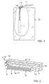
- Fig. 1 illustrates the use of a plug according to the invention.
- the plug 1 in Fig. 1 is connected to e.g. a base station in a cellular radio system.
- a strong RF-field in a casing 12 inside which the plug 1 is arranged.
- the RF-field would cause interference for a non-shielded plug and cable.
- the plug 1 is, however, shielded, and a conventional non-shielded multipolar cable 11 can be used in connection thereto.
- a metal texture net 13 is arranged on the outer surface of the cable 11 inside the casing 12, the net being grounded to the casing 12 by means of connectors 14, and also coupled to the metal casing of the plug 1.
- the plug 1 is preferably encased in a metal casing.
- Fig. 2 illustrates a first preferred embodiment of the plug according to the invention.
- the plug 1 presented in Fig. 2 may be e.g. a 64-pole Euro connector.
- a body portion 2 of the plug 1 is attached by means of screws 15 to a metal casing 16.
- the metal casing comprises an aperture through which the cable 11 is led to the plug.
- the cable 11 consists of a plurality of separate conductors each of which is connected by means of the connectors of the plug (cf. Fig. 3) to a contact 8.
- the contacts 8 connect the conductors to the contacts in a counterpart (not shown) of the plug.
- the left edge of the plug comprises a metal grounding contact 5 designed so that it is grounded when the plug 1 is connected to its counterpart.
- the concept "grounded when the plug is connected to its counterpart" as used herein suggests that when the plug is inserted in a counterpart of a plug in an electric appliance, the grounding contact is grounded either once it comes into contact with a grounding contact in the counterpart or alternatively once it comes directly into contact with the body of the electric appliance.
- Fig. 3 shows the plug of Fig. 2 in partial section taken on the line III - III.
- the parts of the plug 1 are, however, shown apart to simplify the distinction of one from the other.
- Fig. 3 thus illustrates also the assembly of the plug 1.
- the body portion 2 of the plug 1 can be e.g. of plastic.
- the body portion comprises elongated metal connectors 3 to the right end (in Fig. 3) to which one or more cable 11 conductors are connected.
- Metal contacts 8 are arranged at the left ends of the connectors, by means of which the cable 11 conductors are brought into contact with a plug 1 counterpart.
- a sleeve-like tubular capacitor 4 is threaded on the upper connector 3.
- Such a tubular capacitor is preferably threaded on each connector, i.e. even on the lower connector 3 shown in Fig. 3.
- the tubular capacitor 4 is formed of a tubular capacitor known per se and the inner surface forming its first pole can be e.g. of a mixture of lead and tin.
- the outer surface forming the second pole of the capacitor can be e.g. of a mixture of lead and tin.
- a third layer of e.g. some ceramic material is arranged between the inner and outer surfaces formed of the mixture of lead and tin.
- the plug of Fig. 3 comprises additionally a lid portion 9 made of plastic, with apertures 10 through which the connectors 3 penetrate when the lid portion 9 is being connected to the body portion 2. This is when the tubular capacitors 4 are locked in place between the lid portion and the body portion.
- the whole lid portion 9 fits into the metal casing 16 of the plug 1 once the plug is assembled. Hence the lid portion is not shown in Fig. 2.
- the lid portion 9 is provided with a metal grounding plate 17 parallel to its surface, the plate covering essentially the whole surface facing its body portion. However, a plastic projection 18 projecting from the plate 17 so that there is no contact between the end surfaces of the tubular capacitors 4 and the plate 17, is arranged in connection with each aperture 10.
- a flexible metal projection 6 projects from the grounding plate 17, the projection being arranged to press against the outer surface of its respective tubular capacitor 4 when the lid 9 and the body portion 2 are connected.
- the grounding contact 5 shown in the background of Fig. 3 projects from the grounding plate 17. The operation of this contact is described in connection with Fig. 2.
- the flexible metal projections 6 press in a spring-like manner towards the outer surfaces of the tubular capacitors 4, the outer surfaces being thus grounded through the grounding plate 17 and the grounding connector 5.
- the radial force directed to the tubular capacitors 4 brings the inner surfaces of the tubular capacitors 4 into contact with the connector 3.
- the tubular capacitors need not be soldered at all.
- Fig. 3 further shows the metal casing 16 of the plug 1 with an aperture 19 for receiving the cable 11.
- the body portion 2 and the lid portion 9 are pressed together once the tubular capacitors 4 have been mounted and thereafter the body portion 2 is fastened by means of e.g. screws 15 to the casing 16.
- Fig. 4 illustrates a second preferred embodiment of the plug according to the invention.
- Fig. 4 shows a body portion 2' of a plug 1' in partial section.
- the ends of -connectors 3, to which the conductors are supposed to be connected, project towards the reader.
- a tubular capacitor 4 is threaded around each connector 3.
- the embodiment of Fig. 4 differs from that of Fig. 2 and 3 in that in Fig. 4 the plug 1' comprises only two flexible elements 6' through which all tubular capacitors 4 of the plug 1' are grounded.
- the flexible elements 6' can be formed of e.g. spiral springs arranged to contact the outer surfaces of the tubular capacitors 4.
- Fig. 5 is a partial section of the plug of Fig. 4 taken on the line V - V. However, a lid 9' and a metal casing 16', not shown in Fig. 4, have been added to Fig. 5.
- the spiral springs 6' have been compressed when the lid portion 9' has been put in place.
- the lid portion 9' remains in place owing to friction between itself and the connectors 3.
- the spiral springs 6' are shown as ellipses in contact with the tubular capacitors 4.
- Fig. 5 further shows that the plug 1' does not comprise a separate grounding plate; instead the two-piece metal casing 16' of the plug 1' functions as a grounding element against which the spiral springs press when the lid portion 9' is in place.
- the metal casing 16' comprises a grounding contact (not shown) through which it is grounded to a grounding contact in the counterpart of the plug 1' or alternatively directly to the body of an electric appliance.
Landscapes
- Details Of Connecting Devices For Male And Female Coupling (AREA)
- Connector Housings Or Holding Contact Members (AREA)
Abstract
Claims (7)
- Prise électrique mâle (1, 1'), comprenant :une partie formant corps (2, 2'),un connecteur conducteur allongé (3) faisant saillie depuis le corps pour recevoir un ou plusieurs conducteurs, et à une extrémité duquel des moyens de connexion (8) sont installés pour mettre ledit conducteur au contact d'un connecteur situé dans une pièce en regard de la prise,un condensateur tubulaire (4) enfilé autour du connecteur (3) afin de coupler avec le connecteur une surface intérieure formant un premier pôle du condensateur tubulaire, etun moyen de mise à la terre (5, 6, 6', 16', 17) couplé avec une surface extérieure formant un second pôle du condensateur tubulaire (4), caractérisée en ce que le moyen de mise à la terre comporte un élément conducteur souple (6, 6') conçu pour appuyer à la manière d'un ressort contre la surface extérieure du condensateur tubulaire (4) pour mettre à la terre ledit second pôle du condensateur.
- Prise électrique mâle selon la revendication 1, caractérisée en ce qu'elle comprend une pluralité de connecteurs (3) et une pluralité de condensateurs tubulaires (4), un condensateur tubulaire étant enfilé autour de chaque connecteur, le premier pôle dudit condensateur étant connecté à un connecteur, et le second pôle dudit condensateur étant agencé pour être mis à la terre par ledit moyen de mise à la terre (5, 6, 6', 16', 17) lorsque la prise est branchée sur une pièce en regard.
- Prise électrique mâle selon la revendication 2, caractérisée en ce que le moyen de mise à la terre comporte pour chaque condensateur tubulaire un élément conducteur souple séparé (6) qui appuie contre un second pôle de son condensateur tubulaire respectif (4) pour la mise à la terre du pôle.
- Prise électrique mâle selon la revendication 2, caractérisée en ce que le moyen de mise à la terre comporte un élément conducteur souple (6') agencé pour appuyer contre la surface extérieure d'une pluralité de condensateurs tubulaires (4), ledit élément souple (6') mettant ainsi à la terre les seconds pôles de ladite pluralité de condensateurs.
- Prise électrique mâle selon l'une quelconque des revendications 1 à 4, caractérisée en ce que ladite prise (1, 1') comprend une partie formant couvercle (9, 9') séparée de la partie formant corps et pourvue d'une ou plusieurs ouvertures (10) et assemblée avec la partie formant corps (2, 2') de façon que le ou les connecteurs (3) dépassent par les ouvertures du couvercle, grâce à quoi le corps (2, 2') et le couvercle (9, 9') lorsqu'ils sont assemblés l'une avec l'autre, sont appuyés contre les surfaces d'extrémités des condensateurs tubulaires (4) qui entourent les connecteurs afin d'immobiliser les condensateurs tubulaires.
- Prise électrique mâle selon la revendication 5, caractérisée en ce que l'élément souple (6) ou, d'une manière correspondante, les éléments souples sont reliés au couvercle (9).
- Prise électrique mâle selon la revendication 5 ou 6, caractérisée en ce que la mise en place du couvercle (9, 9') amène les éléments souples (6, 6') à être appuyés contre les condensateurs tubulaires, ce qui provoque un fléchissement élastique des éléments analogues à des ressorts, de sorte qu'il se crée une tension interne sous l'influence de laquelle les éléments sont appuyés contre les condensateurs tubulaires (4).
Applications Claiming Priority (3)
| Application Number | Priority Date | Filing Date | Title |
|---|---|---|---|
| FI954036 | 1995-08-28 | ||
| FI954036A FI100146B (fi) | 1995-08-28 | 1995-08-28 | Häiriösuojattu pistoke |
| PCT/FI1996/000460 WO1997008784A1 (fr) | 1995-08-28 | 1996-08-28 | Fiche |
Publications (2)
| Publication Number | Publication Date |
|---|---|
| EP0858683A1 EP0858683A1 (fr) | 1998-08-19 |
| EP0858683B1 true EP0858683B1 (fr) | 2001-11-07 |
Family
ID=8543924
Family Applications (1)
| Application Number | Title | Priority Date | Filing Date |
|---|---|---|---|
| EP96927718A Expired - Lifetime EP0858683B1 (fr) | 1995-08-28 | 1996-08-28 | Fiche |
Country Status (9)
| Country | Link |
|---|---|
| US (1) | US6109972A (fr) |
| EP (1) | EP0858683B1 (fr) |
| JP (1) | JPH11512223A (fr) |
| CN (1) | CN1154205C (fr) |
| AU (1) | AU710640B2 (fr) |
| DE (1) | DE69616816T2 (fr) |
| FI (1) | FI100146B (fr) |
| NZ (1) | NZ315679A (fr) |
| WO (1) | WO1997008784A1 (fr) |
Families Citing this family (3)
| Publication number | Priority date | Publication date | Assignee | Title |
|---|---|---|---|---|
| US6398588B1 (en) * | 1999-12-30 | 2002-06-04 | Intel Corporation | Method and apparatus to reduce EMI leakage through an isolated connector housing using capacitive coupling |
| US7060023B2 (en) * | 2001-09-25 | 2006-06-13 | The Foundry Inc. | Pericardium reinforcing devices and methods of using them |
| US6695769B2 (en) | 2001-09-25 | 2004-02-24 | The Foundry, Inc. | Passive ventricular support devices and methods of using them |
Family Cites Families (6)
| Publication number | Priority date | Publication date | Assignee | Title |
|---|---|---|---|---|
| US4440463A (en) * | 1981-10-26 | 1984-04-03 | The Bendix Corporation | Electrical connector having a metallized plastic grounding insert |
| US4647122A (en) * | 1985-08-16 | 1987-03-03 | Itt Corporation | Filter connector |
| DE3808330A1 (de) * | 1988-03-12 | 1989-09-21 | Standard Elektrik Lorenz Ag | Elektrischer kupplungsstecker mit entstoerfilter und verfahren zu dessen herstellung |
| GB8809854D0 (en) * | 1988-04-26 | 1988-06-02 | Oxley Dev Co Ltd | Removable filter array for multi-way connectors |
| CA2121347C (fr) * | 1991-10-17 | 1998-06-23 | Eric James Paulus | Connecteur a contacts interchangeables |
| DE4219806C2 (de) * | 1992-06-17 | 1994-12-22 | Cannon Electric Gmbh | Filtersteckverbinder |
-
1995
- 1995-08-28 FI FI954036A patent/FI100146B/fi not_active IP Right Cessation
-
1996
- 1996-08-28 US US09/029,758 patent/US6109972A/en not_active Expired - Lifetime
- 1996-08-28 EP EP96927718A patent/EP0858683B1/fr not_active Expired - Lifetime
- 1996-08-28 DE DE69616816T patent/DE69616816T2/de not_active Expired - Fee Related
- 1996-08-28 WO PCT/FI1996/000460 patent/WO1997008784A1/fr not_active Ceased
- 1996-08-28 NZ NZ315679A patent/NZ315679A/xx unknown
- 1996-08-28 CN CNB961965932A patent/CN1154205C/zh not_active Expired - Fee Related
- 1996-08-28 JP JP9509890A patent/JPH11512223A/ja active Pending
- 1996-08-28 AU AU67434/96A patent/AU710640B2/en not_active Ceased
Also Published As
| Publication number | Publication date |
|---|---|
| JPH11512223A (ja) | 1999-10-19 |
| WO1997008784A1 (fr) | 1997-03-06 |
| US6109972A (en) | 2000-08-29 |
| AU6743496A (en) | 1997-03-19 |
| NZ315679A (en) | 1999-07-29 |
| DE69616816T2 (de) | 2002-10-24 |
| AU710640B2 (en) | 1999-09-23 |
| DE69616816D1 (de) | 2001-12-13 |
| FI954036A7 (fi) | 1997-03-01 |
| FI954036A0 (fi) | 1995-08-28 |
| FI100146B (fi) | 1997-09-30 |
| CN1154205C (zh) | 2004-06-16 |
| CN1194732A (zh) | 1998-09-30 |
| EP0858683A1 (fr) | 1998-08-19 |
Similar Documents
| Publication | Publication Date | Title |
|---|---|---|
| US6290538B1 (en) | RJ type coaxial cable connector with visual indicator | |
| US5282759A (en) | Modular jack | |
| KR100289543B1 (ko) | 종단내장 동축 커넥터 | |
| US5835071A (en) | Shielded antenna connector | |
| US11424580B2 (en) | Compact coaxial cable connector for transmitting super high frequency signals | |
| EP1003248A3 (fr) | Connecteur coaxial modulaire coudé | |
| US3509513A (en) | Cables connecting assembly | |
| EP0733274A1 (fr) | Raccord coaxial a regulation d'impedance | |
| KR101034491B1 (ko) | 방해 전자파 차폐용 컨택트 구조 | |
| KR100421434B1 (ko) | 향상된접지특성을가진전기커넥터 | |
| US4396242A (en) | Plug connector assembly | |
| KR102311610B1 (ko) | 초고주파 신호 전송용 소형 동축케이블 커넥터 | |
| EP0858683B1 (fr) | Fiche | |
| GB2254495A (en) | Connecting shielded cable to a pcb or the like. | |
| US20240170864A1 (en) | Plug connector coupled to receptacle connector | |
| CA2301323A1 (fr) | Installation d'antenne sur verre | |
| KR100370859B1 (ko) | 수신장치 | |
| KR100339124B1 (ko) | 송수신 유닛 | |
| JPH06169211A (ja) | アンテナの装着構造 | |
| KR890006518Y1 (ko) | 텔레비젼 안테나 단자의 시일드장치 | |
| US5989038A (en) | Coaxial electrical connector | |
| JP2002117949A (ja) | 高周波同軸コネクタの取付装置 | |
| JPH0122280Y2 (fr) | ||
| JPH07240245A (ja) | 同軸線接続機器と同軸ケーブルの接続方法 | |
| CA1154512A (fr) | Connecteur-isolateur |
Legal Events
| Date | Code | Title | Description |
|---|---|---|---|
| PUAI | Public reference made under article 153(3) epc to a published international application that has entered the european phase |
Free format text: ORIGINAL CODE: 0009012 |
|
| 17P | Request for examination filed |
Effective date: 19980220 |
|
| AK | Designated contracting states |
Kind code of ref document: A1 Designated state(s): BE CH DE DK ES FR GB IT LI NL PT SE |
|
| RAP1 | Party data changed (applicant data changed or rights of an application transferred) |
Owner name: NOKIA NETWORKS OY |
|
| GRAG | Despatch of communication of intention to grant |
Free format text: ORIGINAL CODE: EPIDOS AGRA |
|
| GRAG | Despatch of communication of intention to grant |
Free format text: ORIGINAL CODE: EPIDOS AGRA |
|
| GRAH | Despatch of communication of intention to grant a patent |
Free format text: ORIGINAL CODE: EPIDOS IGRA |
|
| 17Q | First examination report despatched |
Effective date: 20010212 |
|
| GRAH | Despatch of communication of intention to grant a patent |
Free format text: ORIGINAL CODE: EPIDOS IGRA |
|
| GRAA | (expected) grant |
Free format text: ORIGINAL CODE: 0009210 |
|
| AK | Designated contracting states |
Kind code of ref document: B1 Designated state(s): BE CH DE DK ES FR GB IT LI NL PT SE |
|
| PG25 | Lapsed in a contracting state [announced via postgrant information from national office to epo] |
Ref country code: NL Free format text: LAPSE BECAUSE OF FAILURE TO SUBMIT A TRANSLATION OF THE DESCRIPTION OR TO PAY THE FEE WITHIN THE PRESCRIBED TIME-LIMIT Effective date: 20011107 Ref country code: LI Free format text: LAPSE BECAUSE OF FAILURE TO SUBMIT A TRANSLATION OF THE DESCRIPTION OR TO PAY THE FEE WITHIN THE PRESCRIBED TIME-LIMIT Effective date: 20011107 Ref country code: IT Free format text: LAPSE BECAUSE OF FAILURE TO SUBMIT A TRANSLATION OF THE DESCRIPTION OR TO PAY THE FEE WITHIN THE PRESCRIBED TIME-LIMIT;WARNING: LAPSES OF ITALIAN PATENTS WITH EFFECTIVE DATE BEFORE 2007 MAY HAVE OCCURRED AT ANY TIME BEFORE 2007. THE CORRECT EFFECTIVE DATE MAY BE DIFFERENT FROM THE ONE RECORDED. Effective date: 20011107 Ref country code: CH Free format text: LAPSE BECAUSE OF FAILURE TO SUBMIT A TRANSLATION OF THE DESCRIPTION OR TO PAY THE FEE WITHIN THE PRESCRIBED TIME-LIMIT Effective date: 20011107 Ref country code: BE Free format text: LAPSE BECAUSE OF FAILURE TO SUBMIT A TRANSLATION OF THE DESCRIPTION OR TO PAY THE FEE WITHIN THE PRESCRIBED TIME-LIMIT Effective date: 20011107 |
|
| REG | Reference to a national code |
Ref country code: CH Ref legal event code: EP |
|
| REF | Corresponds to: |
Ref document number: 69616816 Country of ref document: DE Date of ref document: 20011213 |
|
| REG | Reference to a national code |
Ref country code: GB Ref legal event code: IF02 |
|
| ET | Fr: translation filed | ||
| PG25 | Lapsed in a contracting state [announced via postgrant information from national office to epo] |
Ref country code: SE Free format text: LAPSE BECAUSE OF FAILURE TO SUBMIT A TRANSLATION OF THE DESCRIPTION OR TO PAY THE FEE WITHIN THE PRESCRIBED TIME-LIMIT Effective date: 20020207 Ref country code: PT Free format text: LAPSE BECAUSE OF FAILURE TO SUBMIT A TRANSLATION OF THE DESCRIPTION OR TO PAY THE FEE WITHIN THE PRESCRIBED TIME-LIMIT Effective date: 20020207 Ref country code: DK Free format text: LAPSE BECAUSE OF FAILURE TO SUBMIT A TRANSLATION OF THE DESCRIPTION OR TO PAY THE FEE WITHIN THE PRESCRIBED TIME-LIMIT Effective date: 20020207 |
|
| RAP2 | Party data changed (patent owner data changed or rights of a patent transferred) |
Owner name: NOKIA CORPORATION |
|
| NLV1 | Nl: lapsed or annulled due to failure to fulfill the requirements of art. 29p and 29m of the patents act | ||
| REG | Reference to a national code |
Ref country code: CH Ref legal event code: PL |
|
| PG25 | Lapsed in a contracting state [announced via postgrant information from national office to epo] |
Ref country code: ES Free format text: LAPSE BECAUSE OF FAILURE TO SUBMIT A TRANSLATION OF THE DESCRIPTION OR TO PAY THE FEE WITHIN THE PRESCRIBED TIME-LIMIT Effective date: 20020530 |
|
| PLBE | No opposition filed within time limit |
Free format text: ORIGINAL CODE: 0009261 |
|
| STAA | Information on the status of an ep patent application or granted ep patent |
Free format text: STATUS: NO OPPOSITION FILED WITHIN TIME LIMIT |
|
| 26N | No opposition filed | ||
| PGFP | Annual fee paid to national office [announced via postgrant information from national office to epo] |
Ref country code: FR Payment date: 20050809 Year of fee payment: 10 |
|
| PGFP | Annual fee paid to national office [announced via postgrant information from national office to epo] |
Ref country code: DE Payment date: 20060824 Year of fee payment: 11 |
|
| REG | Reference to a national code |
Ref country code: FR Ref legal event code: ST Effective date: 20070430 |
|
| PGFP | Annual fee paid to national office [announced via postgrant information from national office to epo] |
Ref country code: GB Payment date: 20070823 Year of fee payment: 12 |
|
| PG25 | Lapsed in a contracting state [announced via postgrant information from national office to epo] |
Ref country code: FR Free format text: LAPSE BECAUSE OF NON-PAYMENT OF DUE FEES Effective date: 20060831 |
|
| PG25 | Lapsed in a contracting state [announced via postgrant information from national office to epo] |
Ref country code: DE Free format text: LAPSE BECAUSE OF NON-PAYMENT OF DUE FEES Effective date: 20080301 |
|
| GBPC | Gb: european patent ceased through non-payment of renewal fee |
Effective date: 20080828 |
|
| PG25 | Lapsed in a contracting state [announced via postgrant information from national office to epo] |
Ref country code: GB Free format text: LAPSE BECAUSE OF NON-PAYMENT OF DUE FEES Effective date: 20080828 |