EP0858823B1 - Trägerstruktur zum Festhalten eines Filtermediums - Google Patents
Trägerstruktur zum Festhalten eines Filtermediums Download PDFInfo
- Publication number
- EP0858823B1 EP0858823B1 EP98101742A EP98101742A EP0858823B1 EP 0858823 B1 EP0858823 B1 EP 0858823B1 EP 98101742 A EP98101742 A EP 98101742A EP 98101742 A EP98101742 A EP 98101742A EP 0858823 B1 EP0858823 B1 EP 0858823B1
- Authority
- EP
- European Patent Office
- Prior art keywords
- protector
- pillar members
- case
- filter medium
- members
- Prior art date
- Legal status (The legal status is an assumption and is not a legal conclusion. Google has not performed a legal analysis and makes no representation as to the accuracy of the status listed.)
- Expired - Lifetime
Links
- 230000001012 protector Effects 0.000 claims description 108
- 239000011347 resin Substances 0.000 claims description 10
- 229920005989 resin Polymers 0.000 claims description 10
- 239000012530 fluid Substances 0.000 claims 2
- 239000013618 particulate matter Substances 0.000 claims 2
- 239000003921 oil Substances 0.000 description 19
- XLYOFNOQVPJJNP-UHFFFAOYSA-N water Substances O XLYOFNOQVPJJNP-UHFFFAOYSA-N 0.000 description 11
- 239000000835 fiber Substances 0.000 description 9
- 239000002002 slurry Substances 0.000 description 9
- 238000001914 filtration Methods 0.000 description 5
- 239000011230 binding agent Substances 0.000 description 4
- 238000000034 method Methods 0.000 description 4
- 239000002184 metal Substances 0.000 description 3
- 229910052751 metal Inorganic materials 0.000 description 3
- XEEYBQQBJWHFJM-UHFFFAOYSA-N Iron Chemical compound [Fe] XEEYBQQBJWHFJM-UHFFFAOYSA-N 0.000 description 2
- 238000000465 moulding Methods 0.000 description 2
- 238000007789 sealing Methods 0.000 description 2
- 238000011144 upstream manufacturing Methods 0.000 description 2
- NIXOWILDQLNWCW-UHFFFAOYSA-N acrylic acid group Chemical group C(C=C)(=O)O NIXOWILDQLNWCW-UHFFFAOYSA-N 0.000 description 1
- 230000005489 elastic deformation Effects 0.000 description 1
- 239000000446 fuel Substances 0.000 description 1
- 229910052742 iron Inorganic materials 0.000 description 1
- 239000010705 motor oil Substances 0.000 description 1
- 230000002093 peripheral effect Effects 0.000 description 1
- 239000005011 phenolic resin Substances 0.000 description 1
- 229920000728 polyester Polymers 0.000 description 1
- 238000004080 punching Methods 0.000 description 1
- 230000000717 retained effect Effects 0.000 description 1
- 229920001187 thermosetting polymer Polymers 0.000 description 1
Images

Classifications
-
- B—PERFORMING OPERATIONS; TRANSPORTING
- B01—PHYSICAL OR CHEMICAL PROCESSES OR APPARATUS IN GENERAL
- B01D—SEPARATION
- B01D27/00—Cartridge filters of the throw-away type
- B01D27/005—Making filter elements not provided for elsewhere
-
- B—PERFORMING OPERATIONS; TRANSPORTING
- B01—PHYSICAL OR CHEMICAL PROCESSES OR APPARATUS IN GENERAL
- B01D—SEPARATION
- B01D27/00—Cartridge filters of the throw-away type
- B01D27/04—Cartridge filters of the throw-away type with cartridges made of a piece of unitary material, e.g. filter paper
- B01D27/06—Cartridge filters of the throw-away type with cartridges made of a piece of unitary material, e.g. filter paper with corrugated, folded or wound material
-
- B—PERFORMING OPERATIONS; TRANSPORTING
- B01—PHYSICAL OR CHEMICAL PROCESSES OR APPARATUS IN GENERAL
- B01D—SEPARATION
- B01D27/00—Cartridge filters of the throw-away type
- B01D27/08—Construction of the casing
-
- B—PERFORMING OPERATIONS; TRANSPORTING
- B01—PHYSICAL OR CHEMICAL PROCESSES OR APPARATUS IN GENERAL
- B01D—SEPARATION
- B01D27/00—Cartridge filters of the throw-away type
- B01D27/10—Safety devices, e.g. by-passes
- B01D27/106—Anti-leakage or anti-return valves
-
- B—PERFORMING OPERATIONS; TRANSPORTING
- B01—PHYSICAL OR CHEMICAL PROCESSES OR APPARATUS IN GENERAL
- B01D—SEPARATION
- B01D29/00—Filters with filtering elements stationary during filtration, e.g. pressure or suction filters, not covered by groups B01D24/00 - B01D27/00; Filtering elements therefor
- B01D29/11—Filters with filtering elements stationary during filtration, e.g. pressure or suction filters, not covered by groups B01D24/00 - B01D27/00; Filtering elements therefor with bag, cage, hose, tube, sleeve or like filtering elements
- B01D29/111—Making filtering elements
-
- B—PERFORMING OPERATIONS; TRANSPORTING
- B01—PHYSICAL OR CHEMICAL PROCESSES OR APPARATUS IN GENERAL
- B01D—SEPARATION
- B01D29/00—Filters with filtering elements stationary during filtration, e.g. pressure or suction filters, not covered by groups B01D24/00 - B01D27/00; Filtering elements therefor
- B01D29/11—Filters with filtering elements stationary during filtration, e.g. pressure or suction filters, not covered by groups B01D24/00 - B01D27/00; Filtering elements therefor with bag, cage, hose, tube, sleeve or like filtering elements
- B01D29/13—Supported filter elements
- B01D29/15—Supported filter elements arranged for inward flow filtration
- B01D29/21—Supported filter elements arranged for inward flow filtration with corrugated, folded or wound sheets
-
- B—PERFORMING OPERATIONS; TRANSPORTING
- B01—PHYSICAL OR CHEMICAL PROCESSES OR APPARATUS IN GENERAL
- B01D—SEPARATION
- B01D2201/00—Details relating to filtering apparatus
- B01D2201/04—Supports for the filtering elements
- B01D2201/0415—Details of supporting structures
-
- Y—GENERAL TAGGING OF NEW TECHNOLOGICAL DEVELOPMENTS; GENERAL TAGGING OF CROSS-SECTIONAL TECHNOLOGIES SPANNING OVER SEVERAL SECTIONS OF THE IPC; TECHNICAL SUBJECTS COVERED BY FORMER USPC CROSS-REFERENCE ART COLLECTIONS [XRACs] AND DIGESTS
- Y10—TECHNICAL SUBJECTS COVERED BY FORMER USPC
- Y10T—TECHNICAL SUBJECTS COVERED BY FORMER US CLASSIFICATION
- Y10T428/00—Stock material or miscellaneous articles
- Y10T428/13—Hollow or container type article [e.g., tube, vase, etc.]
- Y10T428/1352—Polymer or resin containing [i.e., natural or synthetic]
Definitions
- the present invention relates to a protector for holding a filter medium thereon, which is used for a filter.
- JP-U-4-118105 discloses an oil filter including a filter member composed of a filter medium member and a protector for holding the filter medium member thereon to reinforce strength of the filter member and to keep a specific shape of the filter medium member.
- the protector is made of a punching metal plate having plural holes and has a cylindrical shape. The protector is disposed on an inner circumference of the filter medium member, thereby forming the filter member.
- the filter member is located on a specific position within a case by a plate spring.
- the protector cannot be easily scraped when the filter member is exchanged. The handling of the protector is difficult. This is because the protector is made of metal so that the protector is not burned together with the filter medium member.
- the protector for keeping the shape of the filter medium member and the part (the plate spring) for positioning the filter member are respectively provided, resulting in increase in number of parts. The increase in number of the parts causes increase in man-hour for assembling the parts.
- DE-A-19 26 357 shows a filter having a protector for holding a filter medium.
- the protector is made from resin and comprises a plurality of longitudinally extending first pillar members arranged in parallel to each other, and further second pillar members extending in parallel to the first pillar members arranged in a circle
- the pillar members are adapted to support a filter medium.
- US-A-5 306 424 discloses a fuel filter having a protector for the filter medium, which protector has an elastically deformable positioning member protruding from the protector for positioning the protector in the case of the filter.
- a protector 1 in a preferred embodiment of the present invention is used for a filter device 2 for filtering an engine oil as shown in FIG. 1.
- the filter device 2 has a case 3, a filter member 4, a plate 5, a movable valve member 6 made of rubber, a gasket 7, and the like.
- the movable valve member 6 serves as a check valve and a relief valve.
- the case 3 is made of, for example, iron and has a cylindrical shape having a bottom wall at an end thereof and an opening portion at the other end thereof.
- the filter member 4 includes the protector 1 and a filter medium member 8 held on the protector. The protector 1 will be described later in more detail.
- the plate 5 holds the filter member 4 together with the case 3.
- the plate 5 has an oil outlet 5a at a central portion thereof and several oil inlets 5b at a peripheral portion of the oil outlet 5a.
- the oil flowing from an engine flows into the oil inlets 5b, and the oil filtered by the filter member 4 (filter medium member 8) is discharged from the oil outlet 5a.
- the inner circumferential surface of the oil outlet 5a serves as a female screw 5c that is to be engaged with a male screw provided on a mounting base (not shown) on an engine side.
- the movable valve member 6 is disposed between the plate 5 and the filter member 4 and opens and closes the oil inlets 5b of the plate 5. More specifically, the movable valve member 6 opens the oil inlets 5b only when the oil flowing from the engine flows into the oil inlets 5b.
- the gasket 7 is made of, for example, rubber, and disposed on the opening portion of the case 3 for hermetically sealing the case 3 with respect to the mounting base on the engine side.
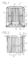
- the protector 1 is molded from resin, and has heat resistance and oil resistance. As shown in FIGS. 2 and 3, the protector 1 has a plurality of pillar members 1a arranged with a comb-like shape in a side view and with a stellate shape in a cross-sectional view.
- the pillar members 1a form a protector body in this embodiment.
- the arrangement of the comb-like shape means that the pillar members 1a are arranged substantially in parallel with each other (in a vertical direction in FIG. 2) with intervals respectively between adjacent two ones.
- the arrangement of the stellate shape is as follows.
- some of the pillar members 1a are arranged with a circular shape, thereby forming a cylindrical portion 1A as a central portion of the stellate shape.
- the other of the pillar members 1a are arranged with several U-shapes to form several (nine in this embodiment) protruding portions 1B of the stellate shape, which protrude outside from an outer circumference in a radial direction of the cylindrical portion 1A.
- the pillar members 1a forming the cylindrical portion 1A are connected to a cylinder member 1C shown in FIG. 2 on a plate side.
- the pillar members 1a forming the cylindrical portion 1A are further connected to a circular connecting member 1b (see FIG. 2) at a generally central portion in a longitudinal direction thereof. Accordingly, the pillar members 1a are fixed in a circumferential direction thereof by the circular connecting member 1b.
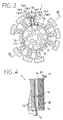
- the connecting member 1b has protruding portions for connecting the pillar members 1a forming the protruding portions 1B as well (see FIGS. 3 and 4). Further, as shown in FIG. 3, several ribs 1c elongating in a radial direction of the cylindrical portion 1A and a circular rib 1d connecting the ribs 1c are provided on an upper end face of the cylindrical portion 1A.
- the cylindrical portion 1A and the protruding portions 1B are explained in more detail.
- a part of the pillar members 1a-1 to 1a-8 are hatched for the explanation.
- the cylindrical part 1A includes three types of pillar members 1a-1 to 1a-3 having generally plate-like shapes and radially arranged to form a part of the circular shape in cross-section of the cylindrical part 1A.
- the pillar members 1a-1 and 1a-3 are connected to the ribs 1c on upper ends thereof, while the pillar member 1a-2 is independent on an upper end thereof. All of the pillar members 1a-1 to 1a-3 are, as mentioned above, connected to the cylinder member 1C at lower ends thereof.
- Each of the protruding portions 1B has five pillar members 1a-4 to 1a-8, and the pillar members 1a-4 to 1a-8 are connected to a plate-like member 1e at upper ends thereof, and are independent at lower end thereof. As mentioned above, all of the pillar members 1a-1 to 1a-8 are connected to the connecting member 1b at the center portion in a longitudinal direction thereof, and elongate in upper and lower directions with respect to the connecting members 1b.
- each of the protruding portions 1B has a positioning member 1D for positioning the protector 1 on a specific location within the case 3.
- the positioning member 1D elongates in an upper direction from an outer circumference on an upper end of the protruding portion 1B and then bends to protrude outside in the radial direction of the cylindrical portion 1A.
- the thus formed positioning member 1D is disposed on the protruding portion 1B such that it can be elastically deformed with respect to the protruding portion 1B.
- the outer surface 1f of the bent portion of the positioning member 1D abuts an inside surface of the case 3 so that the protector 1 is positioned at a specific portion in the case 3 (see FIG. 1).
- the cylinder member 1C is, as shown in FIG. 1, engaged with the movable valve member 6 with air-tightness. Accordingly, the cylinder member 1C serves as a valve seat that moves together with the movable valve member 6 and divides the filter medium member 8 into an upstream side (before filtering) and a downstream side (after filtering).
- the cylinder member 1C serving as a second circular connecting member is disposed on an inner side in the radial direction of the cylindrical portion A compared with the connecting member 1b serving as a first circular connecting member. Therefore, the two circular connecting members can be molded by a die capable of being separated in an axial direction thereof. Further, the cylindrical portion 1A has the ribs 1c radially elongating on the upper end face thereof and disposed on an inner side with respect to the cylinder member 1C to connect several pillar members 1a. Therefore, the shape of the protector 1 is retained with sufficient strength.
- the plate-like members 1e are disposed on an upper ends of the protruding portions 1B to respectively surround the protruding portions of the connecting member 1b in a projected state, thereby retaining the shapes of the protruding portions 1B.
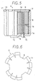
- the filter medium member 8 is, as shown in FIGS. 5 and 6, disposed on the side, upper, and lower surfaces of the protector 1. That is, the filter medium member 8 is disposed on the outer surfaces of the assembled member (protector) composed of a plurality of the pillar members 1a. Accordingly, the protector 1 provides a passage space for the oil inside of the filter medium member 8 while retaining the shape of the filter medium member 8.
- the filter medium member 8 is disposed on the protector 1 in the following way by using a suction apparatus 9 shown in FIG. 7.
- the suction apparatus 9 has a water tank 10 filled with slurry including fibers, an agitator 11 for agitating the slurry within the water tank 10, a suction jig 12 immersed in the slurry within the water tank 10, a suction pump 15, a suction pipe 13 connecting the suction jig 12 and the suction pump 15, a discharge pipe 14, and the like.
- the suction pump 15 sucks the slurry from the water tank 10 through the suction jig 12 and the suction pipe 13 and brings the slurry back into the water tank 10 through the discharge pipe 14.
- the fibers for the filter medium member 8 is preferably made of polyester useful for obtaining high oil resistivity, acrylic useful for obtaining high filtering property, pulp capable of reducing cost, or the like.
- the suction jig 12 has a suction core 12A having a cylindrical shape, and the protector 1 is attached to the outer circumference of the suction core 12A. That is, the protector 1 is used as a part of the suction jig 12 as a suction base.
- the filter medium body 80 is heated again at a specific temperature along with the protector 1 such that the binder resin is hardened. As a result, the filter member 4 composed of the protector 1 and the filter medium member 8 is obtained.
- the binder resin is thermosetting resin such as phenol resin or the like.
- the positioning members 1D are embedded in the filter medium member 8 while exposing the outer surfaces 1f of the bent portions thereof. Therefore, when the filter member 4 is positioned in the case, the outer surfaces 1f of the positioning members 1D abut the inside surface of the case 3 to position the filter member 4 within the case 3. Accordingly, positioning accuracy of the filter member 4 is improved.
- the several positioning members 1D are symmetrically disposed in the protector 1, so that the positioning accuracy of the protector 1 (filter member 4) is further improved.
- the positioning members 1D are formed to be elastically deformed with respect to the protruding portions 1B. Therefore, deviation in positioning of the protector 1 in the case 3 can be absorbed by elastic deformation of the positioning members 1D.
- the protector 1 is made of resin. Therefore, the filter member 4 can be easily scrapped (burned) after its use, so that the handling of the filter member 4 becomes easy compared to a conventional filter member including a protector made of metal.
- the protector 1 is composed of a plurality of the pillar members 1a arranged with the comb-like shape. Therefore, when the protector 1 is molded by a die, the protector 1 is easily taken out from the die in the axial direction thereof. That is, the protector 1 has good moldability.
- the protector 1 when forming the filter medium member 8 on the protector 1, the protector 1 is used as the suction base. Therefore, although the filter medium body 80 is in a sorbet-like state or a cotton-like state just after deposited, the filter medium body 80 can be easily detached from the suction jig 12 together with the protector 1 by holding the protector 1.
- the protector 1 has the connecting member 1b connecting the pillar members 1a of the cylindrical portion 1A and the pillar members 1a of the protruding portions 1B.
- the protector 1 further has the ribs 1c and the cylinder member 1C connecting the pillar members 1a of the cylindrical portion 1A on the upper and lower ends of the cylindrical portion 1A. Accordingly, the pillar members 1a are reinforced, so that the strength (stiffness) of the protector 1 is improved. As a result, the strength of the filter member 4 is improved.
- the cylinder member 1C of the protector 1 is engaged with the movable valve member 6 and serves as the valve seat. Simultaneously, the cylinder member 1C sandwiches the movable valve member 6 in cooperation with the plate 5, so that the upstream side and the downstream side of the filter medium member 8 is hermetically divided by the movable valve member 6. In this case, the movable valve member 6 serves as a sealing member.
- the protector 1 when forming the protector 1 by molding, the protector 1 composed of a plurality of the pillar members 1a is taken out from the die in the axial direction thereof, however, it is not necessary for the protector 1 to be taken out from the die in the axial direction.
- the protector 1 may have a shape capable of being taken out from a die in a radial direction or the like.
- the connecting member 1b is adopted to the protector 1 for connecting the pillar members 1a at the generally central portion in the longitudinal direction of the pillar members 1a.
- several connecting members for connecting the pillar members may be disposed at several portions in the longitudinal direction of the pillar members 1a. In this case, the strength of the protector 1 is more improved. Further, by disposing the several connecting members in different positions in the radial direction of the cylindrical portion 1A, the protector 1 can be easily molded
- the filter medium member 8 is formed form the filter medium body 80 deposited on the protector by the suction process, a filter paper folded into a chrysanthemum-like shape or the like may be used as the filter medium member 8.
- the pillar members 1a of the protector 1 are arranged with the satellite shape having the cylindrical portion 1A and the protruding portions 1B, and the positioning members 1D are respectively disposed on the protruding portions 1B.
- the protector 1 it is not always necessary that the protector 1 has the protruding portions 1B.
- the positioning members 1D may be disposed on the upper end face of the cylindrical portion 1A, and may be connected to the upper end face of the cylindrical portion 1A directly or through some members.
- a protector (1) for holding a filter medium (8) thereon is made of resin and composed of a plurality of pillar members (1a).
- the pillar members (1a) are disposed in parallel with each other in a longitudinal direction thereof and forming a circular shape (1A) with intervals respectively between adjacent two pillar members (1a). Accordingly, the protector (1) can be easily manufactured by molding and can be easily scrapped after its use.
- the protector (1) further has a positioning member (1D) for positioning the protector (1) in a case (3). Accordingly, a number of parts in a filter device can be reduced, resulting in increase in man-hour for assembling the parts.
Landscapes
- Chemical & Material Sciences (AREA)
- Chemical Kinetics & Catalysis (AREA)
- Filtration Of Liquid (AREA)
- Lubrication Details And Ventilation Of Internal Combustion Engines (AREA)
Claims (13)
- Trägerstruktur (1) zum Halten eines Filtermediums (8) zum Abtrennen von Partikeln aus Flüssigkeit, wobei die Trägerstruktur (1) aus Harz gemacht ist und
eine Vielzahl von ersten Stützgliedern (Fig. 3; 1a-1 bis 1a-3) hat, die parallel zu einander, in einer längs laufenden Richtung der ersten Stützglieder (Fig. 3; 1a-1 bis 1a-3) angeordnet sind, und eine Kreisform (Fig. 3; 1A) mit Abständen jeweils zwischen zwei benachbarten Stützgliedern (1a) ausbilden und
eine Vielzahl von hervorstehenden Abschnitten (Fig. 3; 1B) hat, die von der Kreisform (1A) aus der Vielzahl an ersten Stützgliedern (Fig. 3; 1a-1 bis 1a-3) in einer radialen Richtung hervorstehen, wovon jeder aus zweiten Stützgliedern (Fig. 3; 1a-4 bis 1a-8) ausgebildet ist,
dadurch gekennzeichnet, dass jeder der hervorstehenden Abschnitte (Fig. 3; 1B) aus einer Vielzahl von zweiten Stützgliedern (1a-4 bis 1a-8) ausgebildet ist. - Trägerstruktur (1) gemäß Anspruch 1, die ferner ein erstes kreisförmiges Verbindungsglied (1b) hat, welches die ersten Stützglieder (1a) in einer Umfangsrichtung der Kreisform (1A) verbindet.
- Trägerstruktur (1) gemäß Anspruch 2, die ferner ein zweites kreisförmiges Verbindungsglied (1C) hat, das die ersten Stützglieder (1a) in der Umfangsrichtung der Kreisform (1A) verbindet und an einer Position angebracht ist, die von der des ersten kreisförmigen Verbindungsglieds (1b) in einer längs laufenden Richtung der ersten Stützglieder (1a) und in einer radialen Richtung von der Kreisform (1A) abweicht.
- Trägerstruktur (1) gemäß Anspruch 3, wobei das zweite kreisförmige Verbindungsglied (1C) eine zylindrische Form hat und die ersten Stützglieder (1a) an Endabschnitten in der längs laufenden Richtung der ersten Stützglieder (1a) verbindet.
- Trägerstruktur (1) gemäß Anspruch 1, die ferner ein Positionierungsteil (1D) zum Positionieren der Trägerstruktur (1) innerhalb eines Gehäuses (3), durch Berühren des Gehäuses (3), wenn die Trägerstruktur (1) im Gehäuse (3) gehalten ist, hat, wobei das Positionierungsteil (1D) aus Harz gemacht ist und mit den Stützgliedern (1a) verbunden ist.
- Trägerstruktur 1 gemäß Anspruch 1, die ferner ein Positionierungsteil (1D) zum Positionieren der Trägerstruktur (1) innerhalb eines Gehäuses (3), durch Berühren des Gehäuses (3), wenn die Trägerstruktur (1) im Gehäuse (3) gehalten ist, hat, wobei:die ersten Stützglieder (1a) so angeordnet sind, dass sie im Wesentlichen eine zylindrische Form (1A) mit Abständen zwischen zwei benachbarten Stützgliedern (1a) ausbilden; unddas Positionierungsglied (1D) an einem Ende in einer axialen Richtung der zylindrischen Form (1A) aus den ersten Stützgliedern (1a) angebracht ist und mit den ersten Stützgliedern (1a) verbunden ist, um von einer Seitenfläche der zylindrischen Form aus den ersten Stützgliedern (1a), hervorzustehen.
- Trägerstruktur (1) gemäß Anspruch 6, wobei das Positionierungsglied (1D) an den hervorstehenden Abschnitt der Vielzahl von zweiten Stützgliedern (1a) angeschlossen ist.
- Trägerstruktur (1) zum Halten eines Filtermediums (8) zum Abtrennen von Partikeln aus Flüssigkeit, wobei die Trägerstruktur (1) in einem Gehäuse (3) gehalten wird und einen Trägerhauptteil (1A,1B) zum Halten des Filtermediums (8) hat und ein Positionierungsteil (1D) einstückig mit dem Trägerhauptteil (1A,1B) zum Positionieren der Trägerstruktur (1) innerhalb des Gehäuses (3) verbunden ist, wobei das Positionierungsteil (1D) elastisch verformbar ist und vom Trägerhauptteil (1A,1B) hervorsteht,
dadurch gekennzeichnet, dass das Positionierungsteil (1D) in das Filtermedium (8) eingebettet ist, wobei eine äußere Fläche (1f) zum Berühren des Gehäuses (3) freiliegt. - Trägerstruktur (1) gemäß Anspruch 8, wobei:der Trägerhauptteil (1A,1B) eine Vielzahl von Stützgliedern (1a) hat, die parallel zu einander angeordnet sind, um eine zylindrische Form (1A) mit Abständen jeweils zwischen zwei benachbarten Stützgliedern (1a) zu haben; unddas Positionierungsteil (1D) an einem Ende der zylindrischen Form der Stützglieder (1a) angeordnet ist und einstückig mit den Stützgliedern (1a) verbunden ist, um von einer Seitenfläche der zylindrischen Form der Stützglieder (1a) hervorzustehen.
- Trägerstruktur (1) gemäß Anspruch 9, wobei das Positionierungsglied (1D) mehrere Positionierungsabschnitte hat, die entlang eines äußeren Umfangs der zylindrischen Form aus Stützgliedern (1a) angeordnet sind.
- Trägerstruktur (1) gemäß Anspruch 8, wobei das Positionierungsglied (1D) im Hinblick auf den Trägerhauptteil (1A,1B) elastisch verformt ist.
- Trägerstruktur (1) gemäß Anspruch 8, wobei das Filtermedium (8) alleine durch die Trägerstruktur (1) gehalten wird.
- Trägerstruktur (1) gemäß Anspruch 8, wobei die Trägerstruktur (1) das Gehäuse (3) nur über das Positionierungsglied (1D) berührt.
Applications Claiming Priority (6)
| Application Number | Priority Date | Filing Date | Title |
|---|---|---|---|
| JP02071197A JP3684739B2 (ja) | 1997-02-03 | 1997-02-03 | フィルタ用エレメント |
| JP2071197 | 1997-02-03 | ||
| JP02062197A JP3684738B2 (ja) | 1997-02-03 | 1997-02-03 | フィルタ用プロテクタ |
| JP2062197 | 1997-02-03 | ||
| JP20621/97 | 1997-02-03 | ||
| JP20711/97 | 1997-02-03 |
Publications (2)
| Publication Number | Publication Date |
|---|---|
| EP0858823A1 EP0858823A1 (de) | 1998-08-19 |
| EP0858823B1 true EP0858823B1 (de) | 2002-06-12 |
Family
ID=26357600
Family Applications (1)
| Application Number | Title | Priority Date | Filing Date |
|---|---|---|---|
| EP98101742A Expired - Lifetime EP0858823B1 (de) | 1997-02-03 | 1998-02-02 | Trägerstruktur zum Festhalten eines Filtermediums |
Country Status (5)
| Country | Link |
|---|---|
| US (1) | US6070740A (de) |
| EP (1) | EP0858823B1 (de) |
| KR (1) | KR100495470B1 (de) |
| CN (1) | CN1073456C (de) |
| DE (1) | DE69805873T2 (de) |
Families Citing this family (6)
| Publication number | Priority date | Publication date | Assignee | Title |
|---|---|---|---|---|
| BR0014190A (pt) * | 1999-09-22 | 2002-05-21 | Donaldson Co Inc | Construção de filtro de lìquido, método de fabricação e uso |
| US6384369B1 (en) | 1999-09-22 | 2002-05-07 | Donaldson Company, Inc. | Liquid filter construction and methods |
| JP3975977B2 (ja) * | 2003-06-24 | 2007-09-12 | 株式会社デンソー | エレメント製造装置 |
| KR20070011489A (ko) * | 2004-04-13 | 2007-01-24 | 도날드슨 캄파니 인코포레이티드 | 액체 여과용 필터 카트리지 |
| DE102015222423A1 (de) | 2015-11-13 | 2017-05-18 | Mahle International Gmbh | Spin-On Wechselfilter für Flüssigkeiten |
| CN110468934A (zh) * | 2018-05-11 | 2019-11-19 | 福建省泷澄建设集团有限公司 | 一种排水管衔接稳固预埋件 |
Family Cites Families (11)
| Publication number | Priority date | Publication date | Assignee | Title |
|---|---|---|---|---|
| FR562748A (fr) * | 1923-02-27 | 1923-11-17 | Filtre stérilisateur pour tous liquides et procédé pour sa fabrication | |
| US3486626A (en) * | 1968-02-01 | 1969-12-30 | Sam Close | Replaceable medium,extended area filter unit |
| DE1926357A1 (de) * | 1969-05-23 | 1970-11-26 | Carborundum Co | Filterapparat |
| US4038194A (en) * | 1974-04-19 | 1977-07-26 | Johnson & Johnson | Blood filter unit |
| DE3514778C1 (de) * | 1985-04-24 | 1986-08-14 | Knecht Filterwerke Gmbh, 7000 Stuttgart | Filtereinsatz für einen Flüssigkeitsfilter |
| FR2625447A1 (fr) * | 1987-12-30 | 1989-07-07 | Thelinge Jean | Filtre pour carburants et lubrifiants, destine aux moteurs a combustion interne ou a explosion, et son procede de fabrication |
| JPH04118105A (ja) * | 1990-09-10 | 1992-04-20 | Kawasaki Steel Corp | 多段圧延機の形状制御方法 |
| JPH0544205U (ja) * | 1991-11-21 | 1993-06-15 | 京三電機株式会社 | 燃料フイルタ |
| DE4416577C2 (de) * | 1993-05-11 | 1998-07-09 | Hengst Walter Gmbh & Co Kg | Filtereinsatz für ein Filter zur Filterung von flüssigen oder gasförmigen Medien |
| JP3508793B2 (ja) * | 1995-07-28 | 2004-03-22 | 株式会社デンソー | 濾過体およびその製造方法 |
| US5772881A (en) * | 1996-11-08 | 1998-06-30 | Champion Laboratories, Inc. | Non-metallic spin-on filter |
-
1998
- 1998-02-02 DE DE69805873T patent/DE69805873T2/de not_active Expired - Lifetime
- 1998-02-02 US US09/017,200 patent/US6070740A/en not_active Expired - Lifetime
- 1998-02-02 EP EP98101742A patent/EP0858823B1/de not_active Expired - Lifetime
- 1998-02-03 KR KR10-1998-0002985A patent/KR100495470B1/ko not_active Expired - Fee Related
- 1998-02-04 CN CN98106402A patent/CN1073456C/zh not_active Expired - Fee Related
Also Published As
| Publication number | Publication date |
|---|---|
| DE69805873T2 (de) | 2002-12-19 |
| EP0858823A1 (de) | 1998-08-19 |
| DE69805873D1 (de) | 2002-07-18 |
| US6070740A (en) | 2000-06-06 |
| KR19980071038A (ko) | 1998-10-26 |
| CN1200947A (zh) | 1998-12-09 |
| CN1073456C (zh) | 2001-10-24 |
| KR100495470B1 (ko) | 2005-09-30 |
Similar Documents
| Publication | Publication Date | Title |
|---|---|---|
| US5766463A (en) | Fuel filter cartridge | |
| US5863313A (en) | Cylindrical air filter with radially directed seal | |
| US5556542A (en) | Fluid filter assembly | |
| US6962256B2 (en) | Plastic molded center tube assembly | |
| US7458468B2 (en) | Fuel filter diverter | |
| US6823996B2 (en) | Spin-on filter including improved seal arrangement and methods | |
| WO1995032786A1 (en) | Fluid filter assembly for vehicles | |
| EP1495789A1 (de) | Filtervorrichtung für Kraftstoffe | |
| AU706553B2 (en) | A filter element for a fluid filter | |
| JPH08291776A (ja) | フィルタエレメント固定構造 | |
| EP0858823B1 (de) | Trägerstruktur zum Festhalten eines Filtermediums | |
| CN210543733U (zh) | 过滤器组件和过滤器元件 | |
| EP3389815B1 (de) | Filterelement mit endkappe mit starrem verstärkungselement | |
| US5759351A (en) | Method of manufacturing a filter having longitudinal channels by molding from a slurry using thermosetting resin | |
| JP3684738B2 (ja) | フィルタ用プロテクタ | |
| JP3684739B2 (ja) | フィルタ用エレメント | |
| JP2001212409A (ja) | フィルタ用プロテクタ | |
| JPH11267424A (ja) | フィルタのエレメント用コア |
Legal Events
| Date | Code | Title | Description |
|---|---|---|---|
| PUAI | Public reference made under article 153(3) epc to a published international application that has entered the european phase |
Free format text: ORIGINAL CODE: 0009012 |
|
| AK | Designated contracting states |
Kind code of ref document: A1 Designated state(s): DE FR GB |
|
| AX | Request for extension of the european patent |
Free format text: AL;LT;LV;MK;RO;SI |
|
| 17P | Request for examination filed |
Effective date: 19980923 |
|
| AKX | Designation fees paid |
Free format text: DE FR GB |
|
| RBV | Designated contracting states (corrected) |
Designated state(s): DE FR GB |
|
| 17Q | First examination report despatched |
Effective date: 19990825 |
|
| GRAG | Despatch of communication of intention to grant |
Free format text: ORIGINAL CODE: EPIDOS AGRA |
|
| GRAG | Despatch of communication of intention to grant |
Free format text: ORIGINAL CODE: EPIDOS AGRA |
|
| GRAH | Despatch of communication of intention to grant a patent |
Free format text: ORIGINAL CODE: EPIDOS IGRA |
|
| GRAG | Despatch of communication of intention to grant |
Free format text: ORIGINAL CODE: EPIDOS AGRA |
|
| GRAH | Despatch of communication of intention to grant a patent |
Free format text: ORIGINAL CODE: EPIDOS IGRA |
|
| GRAH | Despatch of communication of intention to grant a patent |
Free format text: ORIGINAL CODE: EPIDOS IGRA |
|
| GRAA | (expected) grant |
Free format text: ORIGINAL CODE: 0009210 |
|
| AK | Designated contracting states |
Kind code of ref document: B1 Designated state(s): DE FR GB |
|
| REG | Reference to a national code |
Ref country code: GB Ref legal event code: FG4D |
|
| REF | Corresponds to: |
Ref document number: 69805873 Country of ref document: DE Date of ref document: 20020718 |
|
| ET | Fr: translation filed | ||
| PLBE | No opposition filed within time limit |
Free format text: ORIGINAL CODE: 0009261 |
|
| STAA | Information on the status of an ep patent application or granted ep patent |
Free format text: STATUS: NO OPPOSITION FILED WITHIN TIME LIMIT |
|
| 26N | No opposition filed |
Effective date: 20030313 |
|
| REG | Reference to a national code |
Ref country code: GB Ref legal event code: 746 Effective date: 20030725 |
|
| PGFP | Annual fee paid to national office [announced via postgrant information from national office to epo] |
Ref country code: DE Payment date: 20130131 Year of fee payment: 16 Ref country code: FR Payment date: 20130301 Year of fee payment: 16 Ref country code: GB Payment date: 20130130 Year of fee payment: 16 |
|
| REG | Reference to a national code |
Ref country code: DE Ref legal event code: R119 Ref document number: 69805873 Country of ref document: DE |
|
| GBPC | Gb: european patent ceased through non-payment of renewal fee |
Effective date: 20140202 |
|
| REG | Reference to a national code |
Ref country code: FR Ref legal event code: ST Effective date: 20141031 |
|
| REG | Reference to a national code |
Ref country code: DE Ref legal event code: R119 Ref document number: 69805873 Country of ref document: DE Effective date: 20140902 |
|
| PG25 | Lapsed in a contracting state [announced via postgrant information from national office to epo] |
Ref country code: FR Free format text: LAPSE BECAUSE OF NON-PAYMENT OF DUE FEES Effective date: 20140228 Ref country code: DE Free format text: LAPSE BECAUSE OF NON-PAYMENT OF DUE FEES Effective date: 20140902 Ref country code: GB Free format text: LAPSE BECAUSE OF NON-PAYMENT OF DUE FEES Effective date: 20140202 |