EP0858842B1 - Randentfernung mit Unterbrechung der Luftströmung in der Vorhangbeschichtung - Google Patents
Randentfernung mit Unterbrechung der Luftströmung in der Vorhangbeschichtung Download PDFInfo
- Publication number
- EP0858842B1 EP0858842B1 EP98200198A EP98200198A EP0858842B1 EP 0858842 B1 EP0858842 B1 EP 0858842B1 EP 98200198 A EP98200198 A EP 98200198A EP 98200198 A EP98200198 A EP 98200198A EP 0858842 B1 EP0858842 B1 EP 0858842B1
- Authority
- EP
- European Patent Office
- Prior art keywords
- slot
- blade
- curtain
- liquid
- falling curtain
- Prior art date
- Legal status (The legal status is an assumption and is not a legal conclusion. Google has not performed a legal analysis and makes no representation as to the accuracy of the status listed.)
- Expired - Lifetime
Links
- 238000007766 curtain coating Methods 0.000 title claims description 6
- 230000000903 blocking effect Effects 0.000 title 1
- 239000007788 liquid Substances 0.000 claims description 134
- 238000011010 flushing procedure Methods 0.000 claims description 73
- 239000011248 coating agent Substances 0.000 claims description 40
- 238000000576 coating method Methods 0.000 claims description 40
- 239000008199 coating composition Substances 0.000 claims description 27
- 238000009736 wetting Methods 0.000 claims description 12
- 239000002131 composite material Substances 0.000 claims description 3
- 238000000034 method Methods 0.000 claims description 3
- 238000000151 deposition Methods 0.000 claims description 2
- XLYOFNOQVPJJNP-UHFFFAOYSA-N water Substances O XLYOFNOQVPJJNP-UHFFFAOYSA-N 0.000 description 14
- 230000001050 lubricating effect Effects 0.000 description 12
- 108010010803 Gelatin Proteins 0.000 description 9
- 239000008273 gelatin Substances 0.000 description 9
- 229920000159 gelatin Polymers 0.000 description 9
- 235000019322 gelatine Nutrition 0.000 description 9
- 235000011852 gelatine desserts Nutrition 0.000 description 9
- 238000002474 experimental method Methods 0.000 description 8
- 238000006243 chemical reaction Methods 0.000 description 5
- 238000007711 solidification Methods 0.000 description 5
- 230000008023 solidification Effects 0.000 description 5
- 230000005484 gravity Effects 0.000 description 4
- 239000003795 chemical substances by application Substances 0.000 description 3
- 238000009826 distribution Methods 0.000 description 3
- 239000007787 solid Substances 0.000 description 3
- 239000000243 solution Substances 0.000 description 3
- CSCPPACGZOOCGX-UHFFFAOYSA-N Acetone Chemical compound CC(C)=O CSCPPACGZOOCGX-UHFFFAOYSA-N 0.000 description 2
- 230000015556 catabolic process Effects 0.000 description 2
- 238000006731 degradation reaction Methods 0.000 description 2
- 238000001035 drying Methods 0.000 description 2
- 238000007688 edging Methods 0.000 description 2
- 238000004519 manufacturing process Methods 0.000 description 2
- 239000000463 material Substances 0.000 description 2
- 229920000642 polymer Polymers 0.000 description 2
- 150000001298 alcohols Chemical class 0.000 description 1
- 239000007864 aqueous solution Substances 0.000 description 1
- 210000000988 bone and bone Anatomy 0.000 description 1
- 230000005465 channeling Effects 0.000 description 1
- 238000011109 contamination Methods 0.000 description 1
- 238000004132 cross linking Methods 0.000 description 1
- 239000003431 cross linking reagent Substances 0.000 description 1
- 230000008021 deposition Effects 0.000 description 1
- 230000003292 diminished effect Effects 0.000 description 1
- 238000011156 evaluation Methods 0.000 description 1
- 230000008020 evaporation Effects 0.000 description 1
- 238000001704 evaporation Methods 0.000 description 1
- 238000007689 inspection Methods 0.000 description 1
- 238000005259 measurement Methods 0.000 description 1
- 239000004848 polyfunctional curative Substances 0.000 description 1
- 238000007712 rapid solidification Methods 0.000 description 1
- 239000000376 reactant Substances 0.000 description 1
- 230000000630 rising effect Effects 0.000 description 1
- 239000002904 solvent Substances 0.000 description 1
- 239000004094 surface-active agent Substances 0.000 description 1
- 238000012360 testing method Methods 0.000 description 1
- 239000002699 waste material Substances 0.000 description 1
Images


Classifications
-
- B—PERFORMING OPERATIONS; TRANSPORTING
- B05—SPRAYING OR ATOMISING IN GENERAL; APPLYING FLUENT MATERIALS TO SURFACES, IN GENERAL
- B05C—APPARATUS FOR APPLYING FLUENT MATERIALS TO SURFACES, IN GENERAL
- B05C11/00—Component parts, details or accessories not specifically provided for in groups B05C1/00 - B05C9/00
- B05C11/10—Storage, supply or control of liquid or other fluent material; Recovery of excess liquid or other fluent material
- B05C11/1039—Recovery of excess liquid or other fluent material; Controlling means therefor
-
- B—PERFORMING OPERATIONS; TRANSPORTING
- B05—SPRAYING OR ATOMISING IN GENERAL; APPLYING FLUENT MATERIALS TO SURFACES, IN GENERAL
- B05C—APPARATUS FOR APPLYING FLUENT MATERIALS TO SURFACES, IN GENERAL
- B05C5/00—Apparatus in which liquid or other fluent material is projected, poured or allowed to flow on to the surface of the work
- B05C5/005—Curtain coaters
-
- G—PHYSICS
- G03—PHOTOGRAPHY; CINEMATOGRAPHY; ANALOGOUS TECHNIQUES USING WAVES OTHER THAN OPTICAL WAVES; ELECTROGRAPHY; HOLOGRAPHY
- G03C—PHOTOSENSITIVE MATERIALS FOR PHOTOGRAPHIC PURPOSES; PHOTOGRAPHIC PROCESSES, e.g. CINE, X-RAY, COLOUR, STEREO-PHOTOGRAPHIC PROCESSES; AUXILIARY PROCESSES IN PHOTOGRAPHY
- G03C1/00—Photosensitive materials
- G03C1/74—Applying photosensitive compositions to the base; Drying processes therefor
-
- Y—GENERAL TAGGING OF NEW TECHNOLOGICAL DEVELOPMENTS; GENERAL TAGGING OF CROSS-SECTIONAL TECHNOLOGIES SPANNING OVER SEVERAL SECTIONS OF THE IPC; TECHNICAL SUBJECTS COVERED BY FORMER USPC CROSS-REFERENCE ART COLLECTIONS [XRACs] AND DIGESTS
- Y10—TECHNICAL SUBJECTS COVERED BY FORMER USPC
- Y10S—TECHNICAL SUBJECTS COVERED BY FORMER USPC CROSS-REFERENCE ART COLLECTIONS [XRACs] AND DIGESTS
- Y10S118/00—Coating apparatus
- Y10S118/04—Curtain coater
Definitions
- This invention relates generally to coating apparatus and, more particularly, to the curtain coating of multiple layers.
- the moving support is coated by causing a free falling curtain of coating liquid to impinge onto the moving support to form a layer on said support.
- An apparatus is described and used in US-A-3,508,947 wherein a multilayer composite of a plurality of distinct layers is formed on a slide hopper and caused to impinge onto an object or moving support to form a coated layer thereon.
- US-A-3,508,947 particularly relates to the manufacture of multilayer photographic materials such as photographic film and paper.
- the edges of the curtain In the coating of photographic products it is necessary to constrain the edges of the curtain to eliminate narrowing of the curtain and a reduction in coating width. It is desirable to have the edges of the curtain be internal to the edges of the film or paper base, henceforth this will be referred to as internal edging. Internal edging is preferable to the practice of maintaining a curtain wider than the base and coating over the edges of the base.
- the edge guides are solid surfaces which slow the coating liquids because of drag they produce. This reduction in velocity results in a significant penalty in the maximum coating speed attainable near the edge.
- the prior art teaches introducing a lubricating band of water, or another low viscosity liquid, along the edge guide to reduce the drag and increase the velocity of the coating solutions in the curtain.
- This water layer or low viscosity liquid band must, however, be removed in order to maintain acceptable coating latitude and quality and to avoid any penalty in speed for drying the edges.
- the velocity of the coating liquids must not be reduced in the vicinity of the edge if high speed coating is desired.
- the prior art teaches the use of a vertical slit connected to a vacuum source at the bottom of the edge guide as the means by which the lubricating water is removed. This is described in US-A-4,830,887. This technique tends to slow down the coating liquids as the lubricating layer is being removed, hence reducing the maximum attainable coating speed at the edge. Also, some lubricating liquid may flow beyond the slit and not be captured.
- US-A-5,395,660 describes a method and apparatus by which the lubricating layer of liquid and/or edge of the curtain in a curtain coating operation are removed. This is achieved by having the lubricating liquid and optionally, an adjacent narrow section of the curtain fall onto a thin solid blade. The lubricating liquid and curtain which impinge on the blade are then vacuumed away. This allows the remaining curtain to coat with little or no reduction in velocity due to the removal of the edge band of the falling curtain.
- the instant invention is an improvement to the US-A-5,395,660.
- This device uses a blade and vacuum to remove the edges of curtains at the point of coating ( Figure 1).
- the blade intercepts the edge guide flushing liquid and some portion of the freely falling curtain.
- the vacuum removes these intercepted liquids.
- the vacuum means is a slot connected to a vacuum source.
- the blade and slot together are referred to as a vacuum block. It has been found that coating compositions with a tendency to solidify may cause fouling of the vacuum block according to US-A-5,395,660.
- the solidification can be caused by below ambient temperatures on surfaces of the vacuum block. As the air drawn into the vacuum slot expands, it cools by at least several degrees and lowers the temperature of surrounding surfaces. Coating compositions contacting the block may then solidify.
- a setting polymer such as bone gelatin
- the coating composition When the coating composition is undergoing a cross-linking reaction, the solidification can be caused by this reaction proceeding on contacted surfaces of the vacuum block.
- the coating composition may include the gelatin polymer and a cross-linking agent, or hardener. The rate of this reaction increases with the concentrations of the reactants.
- the solidification can be due to evaporation from wetted surfaces.
- Water is a common volatile component. Common solvents, such as acetone or alcohols, are much more volatile than water.
- the invention solves the problem of the fouling and clogging of the prior art vacuum block.
- the fouling represents solidified coating composition on the block.
- the solution is to distribute flushing liquid so as to encompass the extracted coating compositions. This outcome is surprising, because flushing liquid is already present, and particularly because buildup occurs along the line of three phase contact where the block surface, the flushing liquid, and air meet. Either the edge guide flushing liquid already present can be redistributed, or additional flushing liquid can be supplied and distributed. The key is not the presence of flushing liquid, but its distribution.
- the vacuum slot is spaced uniformly from the curtain by approximately 1 mm.
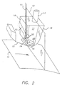
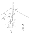
- the improvement shown in Figure 2 involves distributing the edge guide flushing liquid to encompass the intercepted portion of the coating liquids and requires that the flushing liquid make wetting contact with both the blade and the face of the slot. This is accomplished by contacting the face of the slot with the edge guide and by making the face vertical to extend the contact length as shown in Figures 2, 3, and 4. From the region of wetting contact, channels are cut in the slot face and blade surfaces to carry flushing liquid to encompass the intercepted coating liquids. At least one main channel leads to the blade and mates with at least one first channel in the blade that extends across all or a portion of the slot entrance (Figure 3).
- flushing liquid is brought between the blade surface and back surface of the intercepted coating liquids.
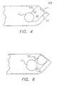
- At least one second channel is cut in the slot face leading to the upper surface of the slot ( Figure 4). Flushing liquid is brought to some portion or all of the top surface of the slot and the side surface of the slot in proximity to the blade edge. In this way, flushing liquid is brought between the top and inboard side surfaces of the slot and the front surface of the intercepted coating liquids.
- additional flushing liquid can be supplied as shown in Figure 5.
- At least one first channel is cut in the blade to bring water from an external supply to the blade surface at the threshold of the slot.
- This channel conveys flushing liquid to a portion or all of the blade surface at the slot entrance.
- the first channel extends at least to the line of apparent intersection of the curtain and blade.
- an externally supplied second channel can be constructed to bring flushing liquid from an external source to the top and inboard sides of the slot.
- a more direct alternative is to create a conduit in the vacuum block that terminates in the top surface of the slot as shown in Figure 6. The outlet of the conduit spans some portion or all of the top surface of the slot.
- the outlet must also be close to the slot entrance, within 1,27 mm (0.050 inch.) or fouling can occur between the slot entrance and the outlet. For this reason the shape of the outlet is preferably squared off as shown in Figure 6.
- the principal advantage of the conduit is that complete capture of the flushing liquid is certain.
- the channels Preferably have a downward inclination to make use of gravity.
- the channels are preferably narrow and of rectangular cross section. Capillary wicking in such channels can be so strong that flushing liquid can be carried even vertically upward, although a downward inclination is preferable.
- Figure 1 shows the edge removal means of the prior art.
- the vacuum slot runs parallel to the curtain at a distance of 1 mm.
- the face of the slot is inclined to the vertical and is not in contact with the edge guide.
- the slot extends to the edge of the blade.
- FIG. 2 shows the addition of flushing distribution means consisting of channels beginning in wetting contact with the edge guide flushing liquid and ending at or near the perimeter of the slot entrance.
- Figure 3 is a view of the apparatus of Figure 2 from above, cross sectioned at the plane of the blade surface. To show the proximity of the edge guide to the vertical face of the vacuum block that facilitates wetting contact, the positions of the edge guide wires and curtain are also indicated although these do not extend to the blade surface.
- Figure 4 is a view of the vacuum block in the plane of the blade viewed perpendicularly. The ends of the channels in the face of the block supplying the blade surface and the top and inboard surfaces of the slot with flushing liquid are shown.
- FIG. 5 is a view of the vacuum block with flushing liquid in addition to the edge guide flushing liquid supplied externally.
- the inlets for the flushing liquid are shown.
- a first channel in the blade delivers the flushing liquid to the threshold of the vacuum slot
- a conduit through the block brings flushing liquid to the top surface of the slot.
- Figure 6 is a view of the vacuum block with externally supplied flushing liquid from below in the plane of the top surface of the slot. The outlet for the internal conduit for the flushing liquid is shown.
- the preferred embodiment is the flush water distributing means that is supplied either from the edge guide flushing liquid or from additional supplies. Examples of the preferred embodiment are shown by Figure 2 and Figure 5.
- Figure 1 shows a curtain 10 and the lower portion of edge guide 11 according to the prior art of US-A-5,395,660.
- the edge guide maintains the width of the curtain from the hopper lip, not shown, to the support 12 to be coated.
- a pin 13 maintains tension and position.
- a band of lubricating liquid 26 adjoins the edge guide and is preferably removed prior to coating the support.
- the lubricating liquid and an adjoining band of the coating composition are intercepted by a solid blade 15 spaced closely to the support and removed by a slot 16 adjacent the blade connected to a vacuum inlet 17.
- the entrance to the vacuum slot 16 runs parallel to the curtain at a distance of 1 mm.
- the unit comprising the blade, slot, and vacuum inlet may be removable from the edge guide and is called the vacuum block 18.
- edge guide flushing liquid Redistributing the edge guide flushing liquid to encompass the intercepted portion of the coating liquids requires that the edge guide flushing liquid makes wetting contact with both the blade and the face of the slot. Wetting is accomplished by contacting a vertical face 19 of the vacuum block 18 with the flushed edge guide 11 as shown in Figures 2 and 3. From the region of wetting contact on vertical face 19, second channel 28 is cut in the slot face 21 and first channel 14 is cut in the blade 15 surfaces to carry flushing liquid to encompass coating liquids intercepted by the blade. At least one main channel (20) leads to the blade and mates with at least one first channel 14 in the blade that extends across all or a portion of the slot entrance as shown in Figure 3.
- At least one second channel 28 is cut in the slot face 21 leading to the upper edge of the slot entrance as shown in Figures 2 and 4. In this way a portion of the edge guide flushing liquid is brought to some portion or all of the top internal surface 22 of the slot 16 and the side surface of the slot in proximity to the blade edge 23. In this way, flushing liquid is brought between these surfaces of the slot and the opposing surface of the intercepted coating liquids.
- additional flushing liquid can be supplied as shown in Figure 5.
- Flushing liquid is supplied to an inlet 24 in the vacuum block 18 to at least one first channel 14 cut in the blade.
- the channels supply flushing liquid to the blade surface at the threshold of slot 16.
- the first channel extends at least to the line of apparent intersection of the curtain 10 and blade 15.
- at least one externally supplied second channel can be constructed to bring flushing liquid to the top surface 22 and inboard surface 23 of slot 16.
- a more direct alternative is to create a conduit 25 in the vacuum block with outlet 27 in the top surface 22 of slot 16.
- the outlet must also be close to the slot entrance, within 1,27 mm (0.050 inch), or fouling can occur between the slot entrance and the outlet.
- the shape of the outlet can be squared off as shown in Figure 6.
- the principal advantage of the conduit over second channels on the outside surface of the channel block is that complete capture of the flushing liquid is certain.
- the channels Preferably have a downward inclination to make use of gravity.
- the channels are preferably narrow and of rectangular cross section. Capillary wicking in such channels can be so strong that flushing liquid can be carried even vertically upward, although a downward inclination is preferable.
- the curtain was anchored on each vertical edge by a pair of wires.
- Edge guides of this type are described in US-A-5,328,726.
- the edge guide flushing liquid was water flowing at 30 cc/min.
- Flush liquid distributing means consisted of a first channel cut transversely into the blade and a second channel above the slot that were in wetting contact with the edge guide flushing water.
- the second channel above the slot had a depth of 0,508 mm (0.020 inch) and a width of 0,813 mm (0.032 inch).
- the first channel in the blade had a depth of 0,381 mm (0.015 inch) and a width of 1,27 mm (0.050 inch) at the threshold of the slot entrance.
- Both edge liquid removal devices intercepted a portion of the free falling curtain of approximately 3,175 mm (0.125 inch), including the edge guide flushing water. Both edge liquid removal devices were connected to a common vacuum source by means of duplicate conduits and fittings. The vacuum levels for both devices were initially set to 3,302 m (130 inches) of water below atmospheric pressure by means of separate air bleed valves.
- both edge liquid removal devices were rinsed with water. After two hours from the start of the experiment, it was observed that the efficiency of the prior art edge liquid removal apparatus in removing the falling curtain was reduced. Less of the coating composition intercepted by the blade was being removed. There was no degradation in the performance of the edge liquid removal device of the invention. Such a reduction in efficiency could result in a shutdown of a coating operation, depending upon drying capabilities.
- edge liquid removal apparatus of the current invention showed no degradation in the efficiency of removal of the intercepted coating composition and flushing liquid.
- the performance of the edge liquid removal apparatus of the current invention in this experiment is very remarkable considering the rapid rate at which the gelatin solidifies due to the chemical reaction with the hardening agent as well as rapid solidification due to chill setting by virtue of the high gelatin concentration.
- the improved performance of the current invention over the prior art is especially remarkable considering that both devices were intercepting the same amounts of coating and flushing liquids.
Landscapes
- Chemical & Material Sciences (AREA)
- Engineering & Computer Science (AREA)
- Materials Engineering (AREA)
- Physics & Mathematics (AREA)
- General Physics & Mathematics (AREA)
- Coating Apparatus (AREA)
- Application Of Or Painting With Fluid Materials (AREA)
Claims (4)
- Verfahren zum Vorhangbeschichten eines Trägers (12) mit zumindest einer Schicht eines flüssigen Beschichtungsmediums, wobei das Verfahren folgende Schritte umfasst:a) Bewegen des Trägers (12) auf einer Bahn durch die Beschichtungszone;b) Erzeugen einer oder mehrerer Schichten des Beschichtungsmediums, um eine zusammengesetzte Schicht zu bilden;c) Erzeugen eines freifallenden Vorhangs (10) aus der zusammengesetzten Schicht innerhalb der Beschichtungszone, der sich quer zu der Bahn erstreckt und auf den bewegten Träger (12) auftrifft;d) seitliches Führen des freifallenden Vorhangs durch Randführungen (11), die so angeordnet sind, dass der Vorhang weniger als die Breite des Trägers (12) beschichtet;e) Halten des freifallenden Vorhangs (10) in Benetzungskontakt mit den Randführungen (11) durch Verteilen von Spülflüssigkeit (26), ausgehend von den den freifallenden Vorhang (10) begrenzenden Randführungen (11);f) Entfernen von Flüssigkeiten vom Rand des freifallenden Vorhangs (10) durch Bereitstellen einer Klinge (15), welche sich von der Randführung (11) in den freifallenden Vorhang (10) erstreckt, um einen Teil des freifallenden Vorhangs (10) abzufangen, und Positionieren der Klinge (15) über der Auftreffstelle des freifallenden Vorhangs (10) auf dem Träger (12), wobei die Klinge (15) so unter einem Winkel in den freifallenden Vorhang (10) hineinragt, dass sie dem Träger (12) an der Stelle am nächsten kommt, an welcher der Teil des freifallenden Vorhangs (10) abgefangen wird, und dass sie an der Randführung am weitesten vom Träger entfernt ist;g) Entfernen der durch die Klinge (15) abgefangenen Flüssigkeiten des freifallenden Vorhangs (10) mittels einer Saugeinrichtung (17); undh) Verteilen von Spülflüssigkeit (26), um die abgefangenen Flüssigkeiten des freifallenden Vorhangs (10) zu umgeben.
- Vorrichtung zum Vorhangbeschichten eines Trägers (12) durch Aufbringen einer oder mehrerer Beschichtungsflüssigkeiten auf einen bewegten Träger (12), wobei die Vorrichtung folgende Komponenten umfasst:eine eine Beschichtungswalze aufweisende Fördereinrichtung zum Bewegen des Trägers (12) mit einer bestimmten Breite auf einer Bahn durch eine Beschichtungszone;einen Trichter zum Erzeugen einer oder mehrerer Fließschichten aus Beschichtungsflüssigkeiten, um einen freifallenden Vorhang (10) zu bilden, welcher sich quer zu der Bahn erstreckt und auf den bewegten Träger (12) auftrifft;Randführungsmittel (11), die voneinander beabstandet sind, um eine Schicht zu erzeugen, deren Abmessung geringer als die Breite des Trägers (12) ist, zum seitlichen Führen des freifallenden Vorhangs (10);eine Spüleinrichtung, welche von der Randführung (11) Flüssigkeit (26) austreten lässt, um den Benetzungskontakt mit dem freifallenden Vorhang (10) aufrecht zu erhalten;eine Flüssigkeitsentfernungseinrichtung zum Abführen von Flüssigkeit aus einem Randbereich des freifallenden Vorhangs (10), wobei die Einrichtung folgende Komponenten aufweist:dadurch gekennzeichnet, dasseine Klinge (15) mit einer in den freifallenden Vorhang (10) hineinragenden Oberfläche, um einen Teil des freifallenden Vorhangs (10) abzufangen, wobei die Klinge (15) den Träger (12) nicht berührt;eine Saugeinrichtung (17) zum Beaufschlagen eines Schlitzes (16) mit einem Unterdruck, wobei der durch die Klinge (15) abgefangene Teil des freifallenden Vorhangs (10) durch den Schlitz (16) derart abgesaugt wird, dass die auf den freifallenden Vorhang (10) ausgeübte Zugkraft auf ein Minimum reduziert wird;der Schlitz (16) mit der Oberfläche der Klinge (15) ausgerichtet und dieser benachbart ist, wobei die Vorderseite des Schlitzes (16) als vertikale Fläche in Kontakt mit der Randführung (11) beginnt, und wobei der Schlitz (16) mit der Ebene des Vorhangs (10) nicht parallel verläuft, so dass sich der Abstand des Schlitzes (16) vom Vorhang (10) bei Annäherung an den Rand der Klinge (15) vergrößert, und der Schlitz (16) vor dem Rand der Klinge (15) endet; undeine Spülflüssigkeit-Verteileinrichtung (14, 20 28) vorgesehen ist, welche mittels der Spülflüssigkeit (26) die in den Schlitz (16) eintretenden Flüssigkeiten des freifallenden Vorhangs (10) umgibt.
- Vorrichtung nach Anspruch 2, dadurch gekennzeichnet, dassa) die Spülflüssigkeit-Verteileinrichtung einen oder mehrere erste Kanäle (14) aufweist, die in Benetzungskontakt mit der Spülflüssigkeit (26) an der Randführung ihren Anfang nehmen, schräg in die Klinge (15) geschnitten sind und sich quer über den gesamten Schlitzeingang oder einen Teil desselben in einem Abstand nicht weiter als die Schnittlinie zwischen Vorhang und Klinge erstrecken;b) die Spülflüssigkeit-Verteileinrichtung einen oder mehrere zweite Kanäle (28) aufweist, die in Benetzungskontakt mit der Spülflüssigkeit (26) an der Randführung ihren Anfang nehmen, schräg über den Schlitz (16) geschnitten sind und so die gesamte Oberfläche (22) und die inneren Seitenflächen (23) des Schlitzes (16) oder einen Teil derselben abfangen;c) jeder der ersten und zweiten Kanäle eine Breite von 0,508 - 2,54 mm (0,020 - 0,1 Zoll) und eine Tiefe von 0,254 - 2,54 mm (0,010 - 0,100 Zoll) aufweist, vorzugsweise eine Breite von 0,508 - 1,524 mm (0,020 - 0,060 Zoll) und eine Tiefe von 0,254 - 2,54 mm (0,010 - 0,040 Zoll);d) die Spülflüssigkeit (26) an der Randführung eine Durchflussleistung von 5 - 50 cm3/min aufweist, vorzugsweise von 30 cm3/min.
- Vorrichtung nach Anspruch 2, dadurch gekennzeichnet, dassa) die Spülflüssigkeit-Verteileinrichtung einen oder mehrere erste Kanäle (14) aufweist, die in die Klinge (15) geschnitten sind und extern mit Spülflüssigkeit versorgt werden, wobei sich die Kanäle vom Zuführmittel (24) bis mindestens zur Schnittlinie zwischen Vorhang und Klinge erstrecken und den gesamten Schlitzeingang oder einen Teil desselben überbrücken;b) die Spülflüssigkeit-Verteileinrichtung eine extern mit Spülflüssigkeit versorgte Leitung (25) aufweist, die sich vom Zuführmittel (24) bis zu einem Auslauf (27) in der Oberfläche (22) des Schlitzes (16) erstreckt und dabei einen Teil oder die gesamte Schlitzbreite überbrückt, wobei der Auslauf (27) nicht mehr als 1,27 mm (0,050 Zoll) vom Schlitzeingang zurückversetzt ist;c) jeder der ersten Kanäle (14) eine Breite von 0,508 - 2,54 mm (0,020 - 0,1 Zoll) und eine Tiefe von 0,254 - 2,54 mm (0,010 - 0,100 Zoll) aufweist, vorzugsweise eine Breite von 0,508 - 1,524 mm (0,020 - 0,060 Zoll) und eine Tiefe von 0,254 - 1,016 Zoll);d) den ersten Kanälen (14) Spülflüssigkeit mit einer Durchflussleistung von 5 - 50 cm3/min, vorzugsweise 10 cm3/min, zugeführt wird;e) der Leitung (25) Spülflüssigkeit mit einer Durchflussleistung von 10 - 100 cm3/min, vorzugsweise 30 cm3/min, zugeführt wird.
Applications Claiming Priority (2)
| Application Number | Priority Date | Filing Date | Title |
|---|---|---|---|
| US08/795,097 US5763013A (en) | 1997-02-05 | 1997-02-05 | Edge removal apparatus including air-flow blocking means for curtain coating |
| US795097 | 1997-02-05 |
Publications (3)
| Publication Number | Publication Date |
|---|---|
| EP0858842A2 EP0858842A2 (de) | 1998-08-19 |
| EP0858842A3 EP0858842A3 (de) | 1999-07-14 |
| EP0858842B1 true EP0858842B1 (de) | 2001-07-25 |
Family
ID=25164659
Family Applications (1)
| Application Number | Title | Priority Date | Filing Date |
|---|---|---|---|
| EP98200198A Expired - Lifetime EP0858842B1 (de) | 1997-02-05 | 1998-01-24 | Randentfernung mit Unterbrechung der Luftströmung in der Vorhangbeschichtung |
Country Status (4)
| Country | Link |
|---|---|
| US (1) | US5763013A (de) |
| EP (1) | EP0858842B1 (de) |
| JP (1) | JP4071341B2 (de) |
| DE (1) | DE69801170T2 (de) |
Families Citing this family (16)
| Publication number | Priority date | Publication date | Assignee | Title |
|---|---|---|---|---|
| DE19829449A1 (de) * | 1998-07-01 | 2000-01-05 | Voith Sulzer Papiertech Patent | Auftragsvorrichtung und Auftragsverfahren |
| US5976251A (en) * | 1998-12-17 | 1999-11-02 | Eastman Kodak Company | Inlet for introducing water to wire edge guides for curtain coating |
| DE10032430A1 (de) * | 2000-07-04 | 2002-01-17 | Voith Paper Patent Gmbh | Auftragsvorrichtung |
| US6887312B1 (en) | 2001-03-06 | 2005-05-03 | Voith Paper Patent Gmbh | Applicator |
| DE10110633A1 (de) * | 2001-03-06 | 2002-09-19 | Voith Paper Patent Gmbh | Auftragsvorrichtung |
| US6610148B2 (en) | 2001-11-26 | 2003-08-26 | Eastman Kodak Company | Curtain coating startup apparatus |
| AU2002359703A1 (en) | 2001-12-13 | 2003-06-23 | Dow Global Technologies Inc. | Method and apparatus for curtain coating |
| WO2003049870A1 (en) | 2001-12-13 | 2003-06-19 | Dow Global Technologies Inc. | Method and apparatus for curtain coating |
| US6924006B2 (en) * | 2002-11-01 | 2005-08-02 | Eastman Kodak Company | Lip preparation apparatus and method for improving the uniformity of a liquid curtain in a curtain coating system |
| EP1793937B1 (de) * | 2004-09-09 | 2009-11-18 | Avery Dennison Corporation | Vorhangbeschichtungsverfahren |
| FI121189B (fi) * | 2007-10-17 | 2010-08-13 | Metso Paper Inc | Reunaohjain ja menetelmä verhopäällystyksessä muodostettavan reunaohjaimen toiminta-ajan pidentämiseksi |
| KR20110000664A (ko) * | 2008-03-26 | 2011-01-04 | 쓰리엠 이노베이티브 프로퍼티즈 컴파니 | 둘 이상의 유체를 슬라이드 코팅하는 방법 |
| BRPI0910275A2 (pt) * | 2008-03-26 | 2015-09-29 | 3M Innovative Properties Co | métodos de aplicação de fluidos como um revestimento de deslizamento contendo precursores poliméricos de múltiplas unidades |
| US20110014391A1 (en) * | 2008-03-26 | 2011-01-20 | Yapel Robert A | Methods of slide coating two or more fluids |
| US8522713B2 (en) * | 2008-07-22 | 2013-09-03 | Ricoh Company, Ltd. | Curtain coating method and curtain coating apparatus |
| JP5169571B2 (ja) * | 2008-07-22 | 2013-03-27 | 株式会社リコー | カーテン塗布方法及び装置 |
Family Cites Families (9)
| Publication number | Priority date | Publication date | Assignee | Title |
|---|---|---|---|---|
| US3508947A (en) * | 1968-06-03 | 1970-04-28 | Eastman Kodak Co | Method for simultaneously applying a plurality of coated layers by forming a stable multilayer free-falling vertical curtain |
| DE3468544D1 (en) * | 1984-10-05 | 1988-02-11 | Agfa Gevaert Nv | Method and apparatus for curtain coating |
| US4830887A (en) * | 1988-04-22 | 1989-05-16 | Eastman Kodak Company | Curtain coating method and apparatus |
| WO1990000939A1 (en) * | 1988-07-20 | 1990-02-08 | Eastman Kodak Company | Curtain coating edge control method and apparatus |
| JP2807949B2 (ja) | 1992-11-10 | 1998-10-08 | 東洋紡績株式会社 | α−アミラーゼ活性測定用試薬および測定方法 |
| US5328726A (en) * | 1992-11-19 | 1994-07-12 | Eastman Kodak Company | Curtain coating method and apparatus using dual wire edge guides |
| EP0606038B1 (de) * | 1993-01-07 | 1999-08-18 | Eastman Kodak Company | Vorrichtung zur Vorhangbeschichtung mit Randentfernung |
| DE19513531A1 (de) * | 1995-04-10 | 1996-10-17 | Du Pont Deutschland | Verfahren und Vorrichtung zur Verminderung von Störungen beim Vorhanggießen |
| DE59506354D1 (de) * | 1995-04-26 | 1999-08-12 | Ilford Imaging Ch Gmbh | Verfahren und Vorrichtung zur Vorhangbeschichtung eines bewegten Trägers |
-
1997
- 1997-02-05 US US08/795,097 patent/US5763013A/en not_active Expired - Lifetime
-
1998
- 1998-01-24 DE DE69801170T patent/DE69801170T2/de not_active Expired - Lifetime
- 1998-01-24 EP EP98200198A patent/EP0858842B1/de not_active Expired - Lifetime
- 1998-02-05 JP JP02444598A patent/JP4071341B2/ja not_active Expired - Fee Related
Also Published As
| Publication number | Publication date |
|---|---|
| DE69801170T2 (de) | 2002-03-28 |
| JP4071341B2 (ja) | 2008-04-02 |
| DE69801170D1 (de) | 2001-08-30 |
| EP0858842A2 (de) | 1998-08-19 |
| US5763013A (en) | 1998-06-09 |
| JPH10216596A (ja) | 1998-08-18 |
| EP0858842A3 (de) | 1999-07-14 |
Similar Documents
| Publication | Publication Date | Title |
|---|---|---|
| US5763013A (en) | Edge removal apparatus including air-flow blocking means for curtain coating | |
| EP0858843B1 (de) | Randentfernung in der Vorhangbeschichtung | |
| US7101592B2 (en) | Method and apparatus for curtain coating | |
| US7169445B2 (en) | Method and apparatus for curtain coating | |
| AU616009B2 (en) | Curtain coating method and apparatus | |
| US6982003B2 (en) | Method and apparatus for curtain coating | |
| EP0606038B1 (de) | Vorrichtung zur Vorhangbeschichtung mit Randentfernung | |
| US5017408A (en) | Curtain coating start/finish method and apparatus | |
| US5328726A (en) | Curtain coating method and apparatus using dual wire edge guides | |
| EP0943961B1 (de) | Vorhangsbeschichtungsapparat und Verfahren mit stufenloser Einstellung | |
| EP0649054B1 (de) | Vorrichtung und Verfahren für interne Kantenführungsstreifen | |
| EP0651285B1 (de) | Auffangbehälter mit Seitenwänden zur Vorbereitung von Vorhangbegiessern | |
| US6610148B2 (en) | Curtain coating startup apparatus | |
| JP3188020B2 (ja) | ブレードレス コータ | |
| JP3861436B2 (ja) | 塗工装置 | |
| JP4399980B2 (ja) | カーテンコータのエアーカット装置 | |
| JP3702128B2 (ja) | 塗工装置 |
Legal Events
| Date | Code | Title | Description |
|---|---|---|---|
| PUAI | Public reference made under article 153(3) epc to a published international application that has entered the european phase |
Free format text: ORIGINAL CODE: 0009012 |
|
| AK | Designated contracting states |
Kind code of ref document: A2 Designated state(s): DE |
|
| AX | Request for extension of the european patent |
Free format text: AL;LT;LV;MK;RO;SI |
|
| PUAL | Search report despatched |
Free format text: ORIGINAL CODE: 0009013 |
|
| AK | Designated contracting states |
Kind code of ref document: A3 Designated state(s): AT BE CH DE DK ES FI FR GB GR IE IT LI LU MC NL PT SE |
|
| AX | Request for extension of the european patent |
Free format text: AL;LT;LV;MK;RO;SI |
|
| 17P | Request for examination filed |
Effective date: 19991211 |
|
| AKX | Designation fees paid |
Free format text: DE FR GB |
|
| GRAG | Despatch of communication of intention to grant |
Free format text: ORIGINAL CODE: EPIDOS AGRA |
|
| 17Q | First examination report despatched |
Effective date: 20000918 |
|
| GRAG | Despatch of communication of intention to grant |
Free format text: ORIGINAL CODE: EPIDOS AGRA |
|
| GRAH | Despatch of communication of intention to grant a patent |
Free format text: ORIGINAL CODE: EPIDOS IGRA |
|
| RBV | Designated contracting states (corrected) |
Designated state(s): DE |
|
| GRAH | Despatch of communication of intention to grant a patent |
Free format text: ORIGINAL CODE: EPIDOS IGRA |
|
| GRAA | (expected) grant |
Free format text: ORIGINAL CODE: 0009210 |
|
| AK | Designated contracting states |
Kind code of ref document: B1 Designated state(s): DE |
|
| REF | Corresponds to: |
Ref document number: 69801170 Country of ref document: DE Date of ref document: 20010830 |
|
| PLBE | No opposition filed within time limit |
Free format text: ORIGINAL CODE: 0009261 |
|
| STAA | Information on the status of an ep patent application or granted ep patent |
Free format text: STATUS: NO OPPOSITION FILED WITHIN TIME LIMIT |
|
| 26N | No opposition filed | ||
| PGFP | Annual fee paid to national office [announced via postgrant information from national office to epo] |
Ref country code: DE Payment date: 20120131 Year of fee payment: 15 |
|
| PG25 | Lapsed in a contracting state [announced via postgrant information from national office to epo] |
Ref country code: DE Free format text: LAPSE BECAUSE OF NON-PAYMENT OF DUE FEES Effective date: 20130801 |
|
| REG | Reference to a national code |
Ref country code: DE Ref legal event code: R119 Ref document number: 69801170 Country of ref document: DE Effective date: 20130801 |