EP0858865A2 - Verfahren und Vorrichtung zum Abrichten von Schleifscheiben mit profilierter Arbeitsfläche - Google Patents
Verfahren und Vorrichtung zum Abrichten von Schleifscheiben mit profilierter Arbeitsfläche Download PDFInfo
- Publication number
- EP0858865A2 EP0858865A2 EP98102464A EP98102464A EP0858865A2 EP 0858865 A2 EP0858865 A2 EP 0858865A2 EP 98102464 A EP98102464 A EP 98102464A EP 98102464 A EP98102464 A EP 98102464A EP 0858865 A2 EP0858865 A2 EP 0858865A2
- Authority
- EP
- European Patent Office
- Prior art keywords
- dressing
- grinding wheel
- dressing roller
- roller
- hard metal
- Prior art date
- Legal status (The legal status is an assumption and is not a legal conclusion. Google has not performed a legal analysis and makes no representation as to the accuracy of the status listed.)
- Granted
Links
Images

Classifications
-
- B—PERFORMING OPERATIONS; TRANSPORTING
- B24—GRINDING; POLISHING
- B24B—MACHINES, DEVICES, OR PROCESSES FOR GRINDING OR POLISHING; DRESSING OR CONDITIONING OF ABRADING SURFACES; FEEDING OF GRINDING, POLISHING, OR LAPPING AGENTS
- B24B53/00—Devices or means for dressing or conditioning abrasive surfaces
- B24B53/06—Devices or means for dressing or conditioning abrasive surfaces of profiled abrasive wheels
- B24B53/065—Devices or means for dressing or conditioning abrasive surfaces of profiled abrasive wheels having other than straight profiles, e.g. crowned
-
- B—PERFORMING OPERATIONS; TRANSPORTING
- B24—GRINDING; POLISHING
- B24B—MACHINES, DEVICES, OR PROCESSES FOR GRINDING OR POLISHING; DRESSING OR CONDITIONING OF ABRADING SURFACES; FEEDING OF GRINDING, POLISHING, OR LAPPING AGENTS
- B24B53/00—Devices or means for dressing or conditioning abrasive surfaces
- B24B53/12—Dressing tools; Holders therefor
- B24B53/14—Dressing tools equipped with rotary rollers or cutters; Holders therefor
Definitions
- the invention relates to a method and a device for dressing grinding wheels with profiled Work surface by means of a dressing roller, in which one Grinding wheel and dressing roller, the surface with Material of higher hardness than that of the dressing Grinding wheel is occupied, with the same peripheral speed can circulate and with high pressure compresses.
- the diamond-set disc was subject to only one very little wear, which only came about that the contact between the grinding wheel and the Dressing roll was not punctiform, but on one radial line took place. Because the diamond coverage extended itself on both sides and across the peripheral surface the dressing roller rounded on its surface. As for the destruction of the binder bridges forces to be exerted on the wheel to be dressed the diamond-set dressing rollers were very high however, should be quite thin in order to get fine curves of the It turned out to be possible to edit the cross-section of the pane through the constant appearance of side forces Difficulties.
- the diamond-set dressing rollers needed lateral support with a shorter radial Extension in the form of hard metal disks, which however the geometrical scope due to its dimensions and thus restricted the possible applications.
- Disc-shaped diamond tools with a diamond coating an end face of a hard metal disc or between two faces of hard metal discs are from the EP 0 410 481 became known. Your area of application is that Grinding workpieces.
- the invention avoids the disadvantages of the prior art Technology. It is the object of the invention with simple Means create a way of abrasion in the process of crushing mentioned at the beginning different surface speeds between Avoid grinding wheel and dressing roller and thereby to achieve long service life of the dressing tool.
- the invention is that as a dressing roller used a circular flat carbide disc, the one face just covered with diamond material, that one grinding wheel and dressing roller to each other that between grinding wheel and dressing roller just an almost punctiform touch takes place and that the contact pressure between Select grinding wheel and dressing roller so high that on Point of contact the binder bridges between the break individual grinding wheels of the grinding wheel.
- the punctiform contact ensures that the Contact forces do not need to be as high as in flat touch. That is also the reason why the necessary reaction forces due to the thin diamond coating be picked up without damage when pressed can.
- This setting on point contact is turned on by the dressing roller determined the currently processed surface of the appropriate grinding wheel to be dressed reached angle. This can be automated by a control device respectively.
- the targets are set up for crash use by making a hole centrally in these disks cuts to get a washer that one can then clamp in the tool holder.
- the one with this Process step waste namely a Circular disc with a smaller diameter can be used for the Continue to use the stock of cutter bars and these Circular disc with a smaller diameter also in Split pieces.
- the production of a dressing roll for the implementation is expediently carried out by placing it in a circular hard metal disc, one end for other purposes is just covered with diamond material, centrally a hole incorporated, and introduces a mandrel in this hole.
- a device for dressing grinding wheels with profiled work surface consisting of a holder for the dressing Grinding wheel, a holder for the dressing roller and a drive device and a press device, through which the dressing roller and the Grinding wheel are pressed together
- the dressing roller is a hard metal disc, one end face with polycrystalline diamond material is just coated and in which is a central hole that the Carbide disc is accommodated in a receptacle, which holds the carbide disc in one position which is just a point contact between the Carbide wheel and the grinding wheel to be dressed takes place and that the pressing device for a contact pressure designed between grinding wheel and dressing roller is so high that it is at the point of contact the binder bridges between the individual Break the grinding wheels of the grinding wheel.
- This device can be made more effective that the layer thickness of the diamond coating of the dressing roller is reduced by electroerosion.
- This device can have a particularly long life if the rotary movement of the dressing roller from the Rotational movement of the grinding wheel is derived.
- This device can be used very effectively if the dressing roller on the diamond material Face a larger diameter than on the opposite side.
- the desired punctiform touch of to be dressed Grinding wheels and dressing roller can be used with this Always adjust the device when the angle of attack the inclusion of the dressing roller is changeable.
- the diamond coating is preferably a polycrystalline Layer.
- PCD polycrystalline diamond discs
- the dressing roller consists of a hard metal disc 1, which is coated on one side with diamond material 2.
- the dressing roller has a hole 3 in the center, in order to Bracket for their rotatable storage can be clamped to be able to.
- the Diameter of the dressing roller in the direction of the End face carrying diamond material can be fillets and the like Dress the shapes on the grinding wheel 4.
- the PCD coating on the hard metal disc can be fixed on the hard metal carrier during the manufacturing process or can be applied as a thin layer using the CVD process.
- the relative speed between diamond grinding wheel and diamond crushing roller is zero when these two roll on each other, rarely is it exactly zero due to the slip.
- a great advantage of this "round design" according to the invention is the fact that the diameter can definitely decrease due to wear and the tool can still be used (eg centerless grinding, the crushing roller only has to be adjusted radially). The control therefore does not need to be adjusted in the axial direction according to the wear of the tool, but only radially. This leads to the possibility of using much simpler controls.
Landscapes
- Engineering & Computer Science (AREA)
- Mechanical Engineering (AREA)
- Grinding-Machine Dressing And Accessory Apparatuses (AREA)
Abstract
Description
- Fig.1
- eine mit Diamantmaterial belegte Abrichtrolle in Stirnseitenansicht,m
- Fig.2
- die mit Diamantmaterial belegte Abrichtrolle in Stirnseitenansicht,
- Fig.3
- eine andere mit Diamantmaterial belegte Abrichtrolle mit sich verjüngendem Durchmesser in Stirnseitenansicht,
- Fig.4
- die mit Diamantmaterial belegte Abrichtrolle in Arbeit an einer profilierten Schleifscheibe an einer Stelle, an der mit achsparallel eingestellten Wellen gearbeitet wird.
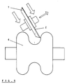
- Fig.5
- die mit Diamantmaterial belegte Abrichtrolle in Arbeit an einer profilierten Schleifscheibe an einer Stelle, an der die Wellen von Abrichtrolle und abzurichtender Schleifscheibe unter einem spitzen Winkel zu einander stehen gearbeitet wird.
Die Relativgeschwindigkeit zwischen Diamant-Schleifscheibe und Diamant-Crushierrolle liegt bei Null, wenn diese beiden aufeinander abrollen, selten ist sie wegen des Schlupfes exakt null.
Ein großer Vorteil dieser erfindungsgemäßen "Rondenausführung" ist die Tatsache, daß der Durchmesser durch Verschleiß durchaus abnehmen kann und das Werkzeug den-noch weiter einsetzbar ist (z.B. Spitzenlosschleifen gerade, die Crushierrolle muß lediglich radial nachgestellt werden). Die Steuerung braucht daher nicht in axialer Richtung entsprechend der Abnutzung des Werkzeuges nachgestellt zu werden, sondern lediglich radial. Das führt zu der Möglichkeit, wesentlich einfachere Steuerungen in Anwendung zu bringen.
Claims (10)
- Verfahren zum Abrichten von Schleifscheiben mit profilierter Arbeitsfläche mittels einer Abrichtrolle,bei dem man Schleifscheibe und Abrichtrolle deren Oberfläche mit Material von höherer Härte als das der abzurichtenden Schleifscheibe belegt ist, mit gleicher Umfangsgeschwindigkeit umlaufen läßt und dabei mit hohem Druck zusammenpreßt,
dadurch gekennzeichnet,daß man als Abrichtrolle eine kreisrunde ebene Hartmetallscheibe verwendet, deren eine Stirnseite mit Diamantmaterial eben belegt,daß man Schleifscheibe und Abrichtrolle derart zueinander anstellt, daß zwischen Schleifscheibe und Abrichtrolle lediglich eine nahezu punktförmige Berührung stattfindetund daß man den Anpreßdruck zwischen Schleifscheibe und Abrichtrolle so hoch wählt, daß am Berührungspunkt die Bindemittelbrücken zwischen den einzelnen Schleifkörpern der Schleifscheibe zerbrechen. - Verfahren nach Anspruch 1,
dadurch gekennzeichnet,daß man vor Beginn der Abrichtarbeiten die Schichtdicke der Diamantbelegung der Abrichtrolle durch Elektroerosion vermindert. - Verfahren nach Anspruch 1
dadurch gekennzeichnet,daß man die Drehbewegung der Abrichtscheibe von der Drehbewegung der Schleifscheibe ableitet. - Verfahren zur Herstellung einer Abrichtrolle für die Durchführung des Abrichtverfahrens nach Anspruch 1,
dadurch gekennzeichnet,daß man in eine kreisrunde Hartmetallscheibe, deren eine Stirnseite mit Diamantmaterial eben belegt ist, zentrisch ein Loch einarbeitet, und in dieses Loch einen Aufnahmedorn einbringt. - Vorrichtung zum Abrichten von Schleifscheiben mit profilierter Arbeitsfläche, bestehend aus einer Aufnahme für die abzurichtende Schleifscheibe, einer Aufnahme für die Abrichtrolle und einer Antriebsvorrichtung sowie einer Preßvorrichtung, durch die die Abrichtrolle und die Schleifscheibe zusammengepreßt sind,
dadurch gekennzeichnet,daß die Abrichtrolle eine Hartmetallscheibe (1) ist, deren eine Stirnseite mit polykristalinem Diamantmaterial (2) eben belegt ist und in die ein zentrales Loch (3) eingearbeitet ist,daß die Hartmetallscheibe (1) in einer Aufnahme aufgenommen ist, die die Hartmetallscheibe (1) in einer Position hält, bei der eine lediglich punktförmige Berührung zwischen der Hartmetallscheibe (1) und der abzurichtenden Schleifscheibe (4) stattfindetund daß die Preßvorrichtung für einen Anpreßdruck zwischen Schleifscheibe (4) und als Abrichtrolle dienender diamantbelegter Hartmetallscheibe (1) ausgelegt ist, der so hoch wählt ist, daß am Berührungspunkt die Bindemittelbrücken zwischen den einzelnen Schleifkörpern der Schleifscheibe zerbrechen. - Vorrichtung nach Anspruch 5,
dadurch gekennzeichnet,daß die Schichtdicke der Diamantbelegung (2) der Abrichtrolle durch Elektroerosion vermindert ist. - Vorrichtung nach Anspruch 5,
dadurch gekennzeichnet,daß die Drehbewegung der Abrichtrolle von der Drehbewegung der Schleifscheibe (4) abgeleitet ist. - Vorrichtung nach Anspruch 5,
dadurch gekennzeichnet,daß die Abrichtrolle an der mit Diamantmaterial (2) belegten Stirnseite einen größeren Durchmesser als auf der gegenüberliegenden Seite aufweist. - Vorrichtung nach Anspruch 5,
dadurch gekennzeichnet,daß der Anstellwinkel der Aufnahme der Abrichtrolle (1) veränderbar ist. - Vorrichtung nach Anspruch 5,
dadurch gekennzeichnet,daß eine elektronische Steuerungsvorrichtung vorgesehen ist, die nach einem vorgebbaren Programm den axialen Vorschub der Abrichtrolle (1) relativ zur abzurichtenden Schleifscheibe (4), den Anstellwinkel und den Preßdruck während des Abrichtvorganges verändert.
Applications Claiming Priority (2)
| Application Number | Priority Date | Filing Date | Title |
|---|---|---|---|
| DE19705989 | 1997-02-17 | ||
| DE19705989 | 1997-02-17 |
Publications (3)
| Publication Number | Publication Date |
|---|---|
| EP0858865A2 true EP0858865A2 (de) | 1998-08-19 |
| EP0858865A3 EP0858865A3 (de) | 1999-02-03 |
| EP0858865B1 EP0858865B1 (de) | 2002-06-26 |
Family
ID=7820460
Family Applications (1)
| Application Number | Title | Priority Date | Filing Date |
|---|---|---|---|
| EP98102464A Expired - Lifetime EP0858865B1 (de) | 1997-02-17 | 1998-02-13 | Verfahren und Vorrichtung zum Abrichten von Schleifscheiben mit profilierter Arbeitsfläche |
Country Status (2)
| Country | Link |
|---|---|
| EP (1) | EP0858865B1 (de) |
| DE (2) | DE59804544D1 (de) |
Cited By (2)
| Publication number | Priority date | Publication date | Assignee | Title |
|---|---|---|---|---|
| EP2230048A1 (de) | 2009-03-19 | 2010-09-22 | Siemens Aktiengesellschaft | Verfahren und Werkzeug zum Abrichten einer topfförmigen Schleifscheibe |
| CN115194652A (zh) * | 2022-08-30 | 2022-10-18 | 常州皓研智能科技有限公司 | 双面抛光设备上抛光盘修整装置及其修整方法 |
Families Citing this family (2)
| Publication number | Priority date | Publication date | Assignee | Title |
|---|---|---|---|---|
| DE10133807A1 (de) * | 2001-07-11 | 2003-01-30 | Bosch Gmbh Robert | Vorrichtung und Verfahren zum Schärfen eines Werkzeugs |
| DE102008010302A1 (de) * | 2008-02-21 | 2009-08-27 | Liebherr-Verzahntechnik Gmbh | Vorrichtung und Verfahren zur Prototypen- und Kleinserienfertigung von Zahnrädern |
Family Cites Families (5)
| Publication number | Priority date | Publication date | Assignee | Title |
|---|---|---|---|---|
| CH631371A5 (de) * | 1978-06-29 | 1982-08-13 | Diamond Sa | Verfahren zur bearbeitung eines teils aus polykristallinem, synthetischem diamant mit metallischem binder. |
| US4760668A (en) * | 1986-07-02 | 1988-08-02 | Alfred Schlaefli | Surface grinding machine and method |
| JPH07100763A (ja) * | 1993-09-30 | 1995-04-18 | Toyoda Mach Works Ltd | 砥石修正方法 |
| DE4436741A1 (de) * | 1994-10-14 | 1996-04-18 | Michael Dr Ing Kaiser | Verfahren und Vorrichtung zum Abrichten von Schleifscheiben mit profilierter Arbeitsfläche |
| JP3004186B2 (ja) * | 1995-01-13 | 2000-01-31 | 真一 東江 | 研削砥石の総形成形用ドレッサとこれを用いた研削砥石の総形成形方法 |
-
1998
- 1998-02-13 DE DE59804544T patent/DE59804544D1/de not_active Expired - Fee Related
- 1998-02-13 EP EP98102464A patent/EP0858865B1/de not_active Expired - Lifetime
- 1998-02-17 DE DE19806591A patent/DE19806591A1/de not_active Withdrawn
Cited By (3)
| Publication number | Priority date | Publication date | Assignee | Title |
|---|---|---|---|---|
| EP2230048A1 (de) | 2009-03-19 | 2010-09-22 | Siemens Aktiengesellschaft | Verfahren und Werkzeug zum Abrichten einer topfförmigen Schleifscheibe |
| US8465344B2 (en) | 2009-03-19 | 2013-06-18 | Siemens Aktiengesellschaft | Curvic wheel dressing |
| CN115194652A (zh) * | 2022-08-30 | 2022-10-18 | 常州皓研智能科技有限公司 | 双面抛光设备上抛光盘修整装置及其修整方法 |
Also Published As
| Publication number | Publication date |
|---|---|
| EP0858865B1 (de) | 2002-06-26 |
| EP0858865A3 (de) | 1999-02-03 |
| DE59804544D1 (de) | 2002-08-01 |
| DE19806591A1 (de) | 1998-10-29 |
Similar Documents
| Publication | Publication Date | Title |
|---|---|---|
| EP2046528B1 (de) | Verfahren zum schleifen einer wendeschneidplatte und schleifscheibe zur durchführung des schleifverfahrens | |
| DE3045760C2 (de) | ||
| EP1285728A2 (de) | Schleifscheibe | |
| EP0048356B2 (de) | Verfahren zum Abrichten von Schleifscheiben | |
| DE2350405A1 (de) | Schleif- oder poliervorrichtung | |
| WO2022128630A1 (de) | Konditionierung eines superabrasiven schleifwerkzeugs | |
| US6361412B1 (en) | Process and rotary point crush truer for dressing grinding wheels with profiled working surfaces | |
| CH635272A5 (de) | Verfahren und abrichtwerkzeug zum abrichten einer schleifscheibe. | |
| EP0858865B1 (de) | Verfahren und Vorrichtung zum Abrichten von Schleifscheiben mit profilierter Arbeitsfläche | |
| EP0898504B1 (de) | Schleifkörper | |
| DE60012320T2 (de) | Drehendes werkzeug mit kombinierter schleif- und bruchwirkung zum erzeugen von profilen oder schnitten auf platten aus zerbrechlichen materialen sowie marmor, granit, stein | |
| DE112008000082B4 (de) | Schneidplatte und Verfahren zur Herstellung einer Schneidplatte | |
| DE102016125921A1 (de) | Werkzeugkombination mit einem Meißelhalter und zwei Meißeln | |
| DE3811782C2 (de) | ||
| DE2743585A1 (de) | Chleifkoerper o.dgl. fuer rundschleifmaschinen | |
| EP1283761B1 (de) | Verfahren zum schleifen von insbesondere nickel enthaltenden metallischen werkstücken | |
| DE3047626C2 (de) | Verfahren zur Bearbeitung von Werkstücken mittels eines Rotationsschneidenwerkzeugs | |
| DE4436741A1 (de) | Verfahren und Vorrichtung zum Abrichten von Schleifscheiben mit profilierter Arbeitsfläche | |
| DE10214792B4 (de) | Verfahren zum Schleifen von Profilen an Werkstücken | |
| WO1990015693A1 (de) | Anwendung eines aus scheiben zusammengesetzten abrichtwerkzeugs zum vor- oder grobbearbeiten von schleifscheiben | |
| DE4443074C1 (de) | Verfahren zur Herstellung von abrasiv belegten Einkegelscheiben, insbesondere Abrichtscheiben | |
| DE29711063U1 (de) | Schleifkörper | |
| DE10007444C2 (de) | Verfahren und Vorrichtung zum Abrichten von Schleifscheiben, sowie Verwendung der Vorrichtung | |
| DE2559660A1 (de) | Verfahren zum abrichten und/oder profilieren von schleifscheiben | |
| DE20116927U1 (de) | System zum Abrichten einer Schleifscheibe |
Legal Events
| Date | Code | Title | Description |
|---|---|---|---|
| PUAI | Public reference made under article 153(3) epc to a published international application that has entered the european phase |
Free format text: ORIGINAL CODE: 0009012 |
|
| AK | Designated contracting states |
Kind code of ref document: A2 Designated state(s): CH DE FR GB IT LI |
|
| AX | Request for extension of the european patent |
Free format text: AL;LT;LV;MK;RO;SI |
|
| PUAL | Search report despatched |
Free format text: ORIGINAL CODE: 0009013 |
|
| AK | Designated contracting states |
Kind code of ref document: A3 Designated state(s): AT BE CH DE DK ES FI FR GB GR IE IT LI LU MC NL PT SE |
|
| AX | Request for extension of the european patent |
Free format text: AL;LT;LV;MK;RO;SI |
|
| 17P | Request for examination filed |
Effective date: 19990129 |
|
| AKX | Designation fees paid |
Free format text: CH DE FR GB IT LI |
|
| 17Q | First examination report despatched |
Effective date: 20000510 |
|
| GRAG | Despatch of communication of intention to grant |
Free format text: ORIGINAL CODE: EPIDOS AGRA |
|
| GRAG | Despatch of communication of intention to grant |
Free format text: ORIGINAL CODE: EPIDOS AGRA |
|
| GRAH | Despatch of communication of intention to grant a patent |
Free format text: ORIGINAL CODE: EPIDOS IGRA |
|
| GRAH | Despatch of communication of intention to grant a patent |
Free format text: ORIGINAL CODE: EPIDOS IGRA |
|
| GRAA | (expected) grant |
Free format text: ORIGINAL CODE: 0009210 |
|
| AK | Designated contracting states |
Kind code of ref document: B1 Designated state(s): CH DE FR GB IT LI |
|
| REG | Reference to a national code |
Ref country code: GB Ref legal event code: FG4D Free format text: NOT ENGLISH |
|
| REG | Reference to a national code |
Ref country code: CH Ref legal event code: EP |
|
| GBT | Gb: translation of ep patent filed (gb section 77(6)(a)/1977) |
Effective date: 20020626 |
|
| REG | Reference to a national code |
Ref country code: CH Ref legal event code: NV Representative=s name: BUECHEL, KAMINSKI & PARTNER PATENTANWAELTE ESTABLI |
|
| REF | Corresponds to: |
Ref document number: 59804544 Country of ref document: DE Date of ref document: 20020801 |
|
| ET | Fr: translation filed | ||
| PG25 | Lapsed in a contracting state [announced via postgrant information from national office to epo] |
Ref country code: GB Free format text: LAPSE BECAUSE OF NON-PAYMENT OF DUE FEES Effective date: 20030213 |
|
| PG25 | Lapsed in a contracting state [announced via postgrant information from national office to epo] |
Ref country code: LI Free format text: LAPSE BECAUSE OF NON-PAYMENT OF DUE FEES Effective date: 20030228 Ref country code: CH Free format text: LAPSE BECAUSE OF NON-PAYMENT OF DUE FEES Effective date: 20030228 |
|
| PLBE | No opposition filed within time limit |
Free format text: ORIGINAL CODE: 0009261 |
|
| STAA | Information on the status of an ep patent application or granted ep patent |
Free format text: STATUS: NO OPPOSITION FILED WITHIN TIME LIMIT |
|
| 26N | No opposition filed |
Effective date: 20030327 |
|
| GBPC | Gb: european patent ceased through non-payment of renewal fee | ||
| REG | Reference to a national code |
Ref country code: CH Ref legal event code: PL |
|
| PG25 | Lapsed in a contracting state [announced via postgrant information from national office to epo] |
Ref country code: FR Free format text: LAPSE BECAUSE OF NON-PAYMENT OF DUE FEES Effective date: 20031031 |
|
| REG | Reference to a national code |
Ref country code: FR Ref legal event code: ST |
|
| PG25 | Lapsed in a contracting state [announced via postgrant information from national office to epo] |
Ref country code: IT Free format text: LAPSE BECAUSE OF NON-PAYMENT OF DUE FEES;WARNING: LAPSES OF ITALIAN PATENTS WITH EFFECTIVE DATE BEFORE 2007 MAY HAVE OCCURRED AT ANY TIME BEFORE 2007. THE CORRECT EFFECTIVE DATE MAY BE DIFFERENT FROM THE ONE RECORDED. Effective date: 20050213 |
|
| PGFP | Annual fee paid to national office [announced via postgrant information from national office to epo] |
Ref country code: DE Payment date: 20060123 Year of fee payment: 9 |
|
| PG25 | Lapsed in a contracting state [announced via postgrant information from national office to epo] |
Ref country code: DE Free format text: LAPSE BECAUSE OF NON-PAYMENT OF DUE FEES Effective date: 20070901 |