EP1285728A2 - Schleifscheibe - Google Patents
Schleifscheibe Download PDFInfo
- Publication number
- EP1285728A2 EP1285728A2 EP02405672A EP02405672A EP1285728A2 EP 1285728 A2 EP1285728 A2 EP 1285728A2 EP 02405672 A EP02405672 A EP 02405672A EP 02405672 A EP02405672 A EP 02405672A EP 1285728 A2 EP1285728 A2 EP 1285728A2
- Authority
- EP
- European Patent Office
- Prior art keywords
- cutting body
- receiving area
- center
- grinding wheel
- grinding
- Prior art date
- Legal status (The legal status is an assumption and is not a legal conclusion. Google has not performed a legal analysis and makes no representation as to the accuracy of the status listed.)
- Granted
Links
Images

Classifications
-
- B—PERFORMING OPERATIONS; TRANSPORTING
- B24—GRINDING; POLISHING
- B24D—TOOLS FOR GRINDING, BUFFING OR SHARPENING
- B24D7/00—Bonded abrasive wheels, or wheels with inserted abrasive blocks, designed for acting otherwise than only by their periphery, e.g. by the front face; Bushings or mountings therefor
- B24D7/06—Bonded abrasive wheels, or wheels with inserted abrasive blocks, designed for acting otherwise than only by their periphery, e.g. by the front face; Bushings or mountings therefor with inserted abrasive blocks, e.g. segmental
-
- B—PERFORMING OPERATIONS; TRANSPORTING
- B24—GRINDING; POLISHING
- B24D—TOOLS FOR GRINDING, BUFFING OR SHARPENING
- B24D7/00—Bonded abrasive wheels, or wheels with inserted abrasive blocks, designed for acting otherwise than only by their periphery, e.g. by the front face; Bushings or mountings therefor
- B24D7/12—Bonded abrasive wheels, or wheels with inserted abrasive blocks, designed for acting otherwise than only by their periphery, e.g. by the front face; Bushings or mountings therefor with apertures for inspecting the surface to be abraded
Definitions
- the invention relates to a grinding wheel according to the preamble of the claim 1.
- grinding wheels provided with diamond-containing cutting bodies and a conditional suitability for the treatment of coated, mineral substrates exhibit.
- the primary use of these grinding wheels is for mineral Substrates designed. From US 3,745,719 is such a grinding wheel with a circular grinding area, a central receiving area, a plurality of passage openings in the grinding area and several protruding from the grinding area, one rectangular base having cutting bodies in different radial Distances from the center of the receiving area are arranged, known.
- the invention is based on the object, an economically producible grinding wheel to create, with their cutting body, the coating of the substrate wedge-shaped can be cut and each cutting body a self-sharpening, sharp-edged cutting edge has.
- the cutting body is a wedge-shaped Cutting the ablated coating achieved.
- the wedge-shaped penetration of the Cutting body into the coating leads to a rapid removal of the same from the surface on which this adheres, without being heated and without that worn coating material sticks to the cutting bodies.
- a special High removal rate is achieved when the angle between the center of the receiving area facing longitudinal side of the cutting body and the radial 45 ° is.
- the good penetration of the cutting body in the coating leads to a smooth running in grinding operation.
- Each cutting body preferably has two matrix zones with different ones Diamond concentration, which in a parallel to the broad side of the cutting body extending Direction are arranged one behind the other. That matrix zone with the higher one Diamond concentration serves to remove the coating and the matrix zone with the Lower diamond concentration has the function of a support back.
- the removal of the coating done with a sharp-edged cutting edge can, which extends over the center of the receiving area facing longitudinal side of the cutter body and extends at the free end of the cutter body, conveniently has the closer to the center of the receiving area
- the first matrix zone has a higher diamond concentration than the center of the Receiving area facing away second matrix zone.
- the diamonds in the first matrix zone have a smaller grain size as the diamonds in the second matrix zone.
- the Diamonds are not as fast as in the second matrix zone.
- Even if the Diamonds break out in the first matrix zone, leading them due to their very small size Do not scale to a blurred cutting edge.
- Due to the larger grain size the diamonds in the second matrix zone break out faster than the diamonds in the first matrix zone.
- the second matrix zone thus allows greater wear of the back support, which forms in the grinding operation and thus the cutting edge of the Cutting body to a certain "exemption" helps.
- the parallel to the broad side of the cutting body corresponds measured width of the matrix zone with the higher diamond concentration of 0.15 bis 0.35 times the width of the cutting body.
- the grinding area is advantageously arranged in a plurality of radially offset from each other, at least partially radially overlapping coaxial with each other Divided annular surfaces, wherein in each annular surface at least one cutting body is arranged.
- An increase in the removal rate of the grinding wheel is preferably characterized ensures that each cutting body is arranged inclined relative to the disk plane.
- the inclined arrangement of the cutting body helps to remove the coating in that the coating material does not lie on a vertical surface during removal but meets an inclined surface of the cutting body and of this under one Angle - the so-called rake angle - is deflected from the ground.
- the inclined surface is the one facing the center of the receiving area Longitudinal side of the cutting body, which at an angle of 80 ° to 90 ° to a is arranged from the grinding area formed disc plane.
- This 80 ° to 90 ° give a rake angle of 10 ° to 20 °, which is between said longitudinal side and a projecting from the disk plane perpendicular.
- a good removal of the removed coating material from the processing area takes place by a plurality of passage openings arranged in the grinding area of the grinding wheel, expediently in an edge region opposite the edge Each cutting body is arranged a passage opening.
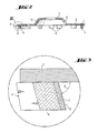
- the grinding wheel shown in FIGS. 1 to 3 serves for the removal of applied to mineral substrate coatings. Neither the coating yet the mineral substrate are shown in Figs. 1 to 3.
- the grinding wheel has a central receiving area 2, several Passage openings 3 in the grinding area 1 and several protruding from the grinding area 1, a rectangular base having cutting body 4.
- the grinding area 1 and the central receiving area 2 are arranged coaxially with each other, but in a parallel spaced from one another to the common central axis direction.
- the Transition 10 between the central receiving area 2 and the grinding area 1 is conical and provided with a plurality of through holes 9.
- the grinding area 1 is composed of a plurality of radially offset from each other, at least partially radially overlapping, coaxially extending annular surfaces D, E, F together, wherein in each annular surface D, E, F four or eight Cutting body 4 are arranged evenly distributed.
- the cutting body 4 thus have different distances from the central receiving area 2.
- Eight cutting body 4 are located in the farthest from the center of the reception area Circular ring surface D arranged. Of the three annular surfaces D, E and F overlap in the radial direction only the annular surfaces E and F.
- each cutter body 4 is at an angle B of 45 ° to one from the center of the receiving area 2 outgoing Radial R arranged.
- the radial runs through the Intersection point S between the center of the receiving area 2 facing Long side 5 and facing away from the center of the receiving area 2 wide side. 6 of the cutting body 4.
- Each cutting body 4 has two matrix zones 7, 8 with different Diamond concentration on, in a parallel to the broad side 6 of the cutter body 4 extending direction are arranged one behind the other.
- a the center of Receiving area 2 closer matrix zone 7 has a higher diamond concentration on as a remote from the center of the receiving area 2 second matrix zone 8.
- the diamonds of the individual matrix zones 7, 8 have different Grain sizes.
- all diamonds are in the first matrix zone 7 is a smaller grain size than the diamonds in the second matrix zone 8.
- the parallel to the broad side 6 of the cutting body 4 measured width of the matrix zone 7 with the higher diamond concentration corresponds to 0.25 times the width of the cutting bodies 4.
- Each cutter 4 is inclined relative to the disk plane, wherein the the center of the receiving area 2 facing longitudinal side 5 of the cutting body. 4 is arranged at an angle A of 85 ° to the receiving area 2.
- the central receiving area facing longitudinal side 5 and the center of the facing broadside 6 together form an edge (K).
- a passage opening 3 In one of the edge K opposite circumferential region of each cutting body 4 is a passage opening 3, through which the abraded coating material, for example with a Suction device, not shown, can be sucked off.
Landscapes
- Engineering & Computer Science (AREA)
- Mechanical Engineering (AREA)
- Polishing Bodies And Polishing Tools (AREA)
Abstract
Description
- Fig.1
- eine erfindungsgemässe Schleifscheibe in der Unteransicht;
- Fig. 2
- einen Schnitt durch die Schleifscheibe entlang der Linie II-II in Fig. 1;
- Fig. 3
- einen vergrösserten Ausschnitt der Schleifscheibe gemäss Fig. 2.
Claims (9)
- Schleifscheibe mit einem kreisringförmigen Schleifbereich (1), einem zentralen Aufnahmebereich (2), mehreren Durchtrittsöffnungen (3) im Schleifbereich (1) und mehreren vom Schleifbereich (1) abragenden, eine rechteckige Grundfläche aufweisenden Schneidkörpern (4), die in unterschiedlichen radialen Abständen vom Zentrum des Aufnahmebereiches (2) angeordnet sind, dadurch gekennzeichnet, dass die dem Zentrum des Aufnahmebereiches (2) zugewandte Längsseite (5) jedes Schneidkörpers (4) unter einem Winkel (B) von 35° bis 55° zu einer vom Zentrum des Aufnahmebereiches (2) ausgehenden Radialen (R) angeordnet ist, die eine Kante (K) tangiert, die von der dem Zentrum des Aufnahmebereiches (2) zugewandten Längsseite (5) und der vom Zentrum des Aufnahmebereiches (2) abgewandten Breitseite (6) des Schneidkörpers (4) gebildet ist.
- Schleifscheibe nach Anspruch 1, dadurch gekennzeichnet, dass jeder Schneidkörper (4) zwei Matrixzonen (7, 8) mit unterschiedlicher Diamantkonzentration aufweist, die in einer parallel zur Breitseite (6) des Schneidkörpers (4) verlaufenden Richtung hintereinander angeordnet sind.
- Schleifscheibe nach Anspruch 2, dadurch gekennzeichnet, dass eine dem Zentrum des Aufnahmebereiches (2) näherliegende erste Matrixzone (7) eine höhere Diamantkonzentration aufweist als eine vom Zentrum des Aufnahmebereiches (2) abgewandte zweite Matrixzone (8).
- Schleifscheibe nach Anspruch 2 oder 3, dadurch gekennzeichnet, dass die Diamanten in der ersten Matrixzone (7) eine grössere Korngrösse besitzen als die Diamanten in der zweiten Matrixzone (8).
- Schleifscheibe nach Anspruch 3 oder 4, dadurch gekennzeichnet, dass die parallel zu der Breitseite (6) der Schneidkörper (4) gemessene Breite der Matrixzone (7) mit der höheren Diamantkonzentration der 0,15- bis 0,35-fache Breite der Schneidkörper (4) entspricht.
- Schleifscheibe nach einem der Ansprüche 1 bis 5, dadurch gekennzeichnet, dass der Schleifbereich (1) in mehrere radial zueinander versetzt angeordnete, sich wenigstens teilweise radial überlappende, koaxial zueinander verlaufende Kreisringflächen (D, E, F) unterteilt ist, wobei in jeder Kreisringfläche (D, E, F) wenigstens ein Schneidkörper (4) angeordnet ist.
- Schleifscheibe nach einem der Ansprüche 1 bis 6, dadurch gekennzeichnet, dass jeder Schneidkörper (4) gegenüber der Scheibenebene geneigt angeordnet ist.
- Schleifscheibe nach Anspruch 7, dadurch gekennzeichnet, dass die dem Zentrum des Aufnahmebereiches (2) zugewandte Längsseite (5) des Schneidkörpers (4) unter einem Winkel (A) von 80° bis 90° zum Aufnahmebereich (2) angeordnet ist.
- Schleifscheibe nach einem der Ansprüche 1 bis 8, dadurch gekennzeichnet, dass in einem der Kante (K) gegenüberliegenden Umfangsbereich jedes Schneidkörpers (4) eine Durchtrittsöffnung (3) angeordnet ist.
Applications Claiming Priority (2)
| Application Number | Priority Date | Filing Date | Title |
|---|---|---|---|
| DE10139762A DE10139762A1 (de) | 2001-08-13 | 2001-08-13 | Schleifscheibe |
| DE10139762 | 2001-08-13 |
Publications (3)
| Publication Number | Publication Date |
|---|---|
| EP1285728A2 true EP1285728A2 (de) | 2003-02-26 |
| EP1285728A3 EP1285728A3 (de) | 2003-09-10 |
| EP1285728B1 EP1285728B1 (de) | 2006-01-25 |
Family
ID=7695326
Family Applications (1)
| Application Number | Title | Priority Date | Filing Date |
|---|---|---|---|
| EP02405672A Expired - Lifetime EP1285728B1 (de) | 2001-08-13 | 2002-08-02 | Schleifscheibe |
Country Status (9)
| Country | Link |
|---|---|
| US (1) | US6926583B2 (de) |
| EP (1) | EP1285728B1 (de) |
| AT (1) | ATE316447T1 (de) |
| AU (1) | AU2002300433B2 (de) |
| DE (2) | DE10139762A1 (de) |
| DK (1) | DK1285728T3 (de) |
| ES (1) | ES2259366T3 (de) |
| NO (1) | NO322762B1 (de) |
| PL (1) | PL198514B1 (de) |
Cited By (2)
| Publication number | Priority date | Publication date | Assignee | Title |
|---|---|---|---|---|
| CN108747857A (zh) * | 2018-06-21 | 2018-11-06 | 江苏赛扬精工科技有限责任公司 | 一种加工未淬火合金钢工件的高线速自锐性cbn砂轮及其制备方法 |
| WO2021018580A1 (de) * | 2019-07-30 | 2021-02-04 | Robert Bosch Gmbh | Schleifwerkzeug |
Families Citing this family (45)
| Publication number | Priority date | Publication date | Assignee | Title |
|---|---|---|---|---|
| US9868100B2 (en) | 1997-04-04 | 2018-01-16 | Chien-Min Sung | Brazed diamond tools and methods for making the same |
| US9238207B2 (en) | 1997-04-04 | 2016-01-19 | Chien-Min Sung | Brazed diamond tools and methods for making the same |
| US9463552B2 (en) | 1997-04-04 | 2016-10-11 | Chien-Min Sung | Superbrasvie tools containing uniformly leveled superabrasive particles and associated methods |
| US9221154B2 (en) | 1997-04-04 | 2015-12-29 | Chien-Min Sung | Diamond tools and methods for making the same |
| US9409280B2 (en) | 1997-04-04 | 2016-08-09 | Chien-Min Sung | Brazed diamond tools and methods for making the same |
| US9199357B2 (en) | 1997-04-04 | 2015-12-01 | Chien-Min Sung | Brazed diamond tools and methods for making the same |
| DE20210085U1 (de) | 2002-07-01 | 2002-09-05 | Büdiam Diamantwerkzeuge R. und N. Büttner GmbH, 35713 Eschenburg | Schneidwerkzeug |
| EP1755840B1 (de) * | 2004-02-26 | 2012-11-14 | Kennametal, Inc. | Schneidwerkzeug für roh- und fertigfräsen |
| US20070060026A1 (en) * | 2005-09-09 | 2007-03-15 | Chien-Min Sung | Methods of bonding superabrasive particles in an organic matrix |
| US9138862B2 (en) | 2011-05-23 | 2015-09-22 | Chien-Min Sung | CMP pad dresser having leveled tips and associated methods |
| US8398466B2 (en) * | 2006-11-16 | 2013-03-19 | Chien-Min Sung | CMP pad conditioners with mosaic abrasive segments and associated methods |
| US9724802B2 (en) | 2005-05-16 | 2017-08-08 | Chien-Min Sung | CMP pad dressers having leveled tips and associated methods |
| US8678878B2 (en) | 2009-09-29 | 2014-03-25 | Chien-Min Sung | System for evaluating and/or improving performance of a CMP pad dresser |
| US8393934B2 (en) | 2006-11-16 | 2013-03-12 | Chien-Min Sung | CMP pad dressers with hybridized abrasive surface and related methods |
| US8622787B2 (en) * | 2006-11-16 | 2014-01-07 | Chien-Min Sung | CMP pad dressers with hybridized abrasive surface and related methods |
| USD536714S1 (en) | 2005-09-16 | 2007-02-13 | 3M Innovative Properties Company | Abrasive article with holes |
| USD538312S1 (en) * | 2005-09-16 | 2007-03-13 | 3M Innovative Properties Company | Abrasive article with holes |
| USD538313S1 (en) | 2005-09-16 | 2007-03-13 | 3M Innovative Properties Company | Abrasive article with holes |
| USD533200S1 (en) * | 2006-02-01 | 2006-12-05 | 3M Innovative Properties Company | Abrasive article with holes |
| USD532800S1 (en) * | 2006-02-01 | 2006-11-28 | 3M Innovative Properties Company | Abrasive article with holes |
| USD541317S1 (en) | 2006-02-01 | 2007-04-24 | 3M Innovative Properties Company | Abrasive article with holes |
| USD543562S1 (en) | 2006-02-01 | 2007-05-29 | 3M Innovative Properties Company | Abrasive article with holes |
| US7147548B1 (en) | 2006-04-03 | 2006-12-12 | Mohsen Mehrabi | Grinding and cutting head |
| US7419422B1 (en) | 2006-10-09 | 2008-09-02 | Mohsen Mehrabi | Rotary cutting head |
| US20080292869A1 (en) * | 2007-05-22 | 2008-11-27 | Chien-Min Sung | Methods of bonding superabrasive particles in an organic matrix |
| KR20100087297A (ko) * | 2007-09-28 | 2010-08-04 | 치엔 민 성 | 모자이크 연마 세그먼트를 포함한 cmp 패드 컨디셔너 및 해당 방법 |
| CN101903131B (zh) * | 2007-11-13 | 2013-01-02 | 宋健民 | Cmp垫修整器 |
| TWI388402B (en) * | 2007-12-06 | 2013-03-11 | Methods for orienting superabrasive particles on a surface and associated tools | |
| USD645065S1 (en) | 2008-05-22 | 2011-09-13 | 3M Innovative Properties Company | Abrasive article with holes |
| CN103221180A (zh) | 2010-09-21 | 2013-07-24 | 铼钻科技股份有限公司 | 具有基本平坦颗粒尖端的超研磨工具及其相关方法 |
| ITMI20110850A1 (it) * | 2011-05-16 | 2012-11-17 | Nicola Fiore | Utensile multi-abrasivo |
| WO2012162430A2 (en) | 2011-05-23 | 2012-11-29 | Chien-Min Sung | Cmp pad dresser having leveled tips and associated methods |
| US9028300B2 (en) * | 2011-08-31 | 2015-05-12 | Ehwa Diamond Industrial Co., Ltd. | Grinding tool adapted to collect grinding particles |
| DE102012001925A1 (de) | 2012-02-02 | 2013-08-08 | Schleif- und Fräswerkzeuge Höhn Ltd. & Co. KG | Oberflächenschleifer, insbesondere Betonschleifer |
| AU354943S (en) * | 2014-03-24 | 2014-04-15 | Diamond abrasive grinding cup wheel | |
| CN104162847A (zh) * | 2014-07-31 | 2014-11-26 | 江苏美杰磨具科技有限公司 | 一种用于路面磨削的金刚石磨盘 |
| TWI690391B (zh) * | 2015-03-04 | 2020-04-11 | 美商聖高拜磨料有限公司 | 磨料製品及使用方法 |
| JP2016168660A (ja) * | 2015-03-13 | 2016-09-23 | 株式会社ディスコ | 研削ホイール |
| DE102017216175A1 (de) * | 2017-09-13 | 2019-03-14 | Robert Bosch Gmbh | Schleifartikel |
| JP6991043B2 (ja) * | 2017-11-22 | 2022-02-03 | 東京エレクトロン株式会社 | 基板載置台 |
| JP7621755B2 (ja) | 2020-08-25 | 2025-01-27 | 株式会社ディスコ | 研削ホイール、及びウエーハの研削方法 |
| CN113370087A (zh) * | 2021-06-28 | 2021-09-10 | 江苏亚达工具有限公司 | 一种高稳定性金刚石磨轮 |
| JP2023038068A (ja) * | 2021-09-06 | 2023-03-16 | 株式会社ディスコ | 被加工物の研削方法 |
| CN115415945B (zh) * | 2022-09-28 | 2024-03-19 | 江苏锋泰工具有限公司 | 一种纯干式金刚石磨盘及其制造方法 |
| DE102024131486A1 (de) * | 2024-10-29 | 2026-04-30 | Audi Hungaria Zrt | Stirnschleifwerkzeug sowie Doppelseiten-Planschleifmaschine |
Family Cites Families (10)
| Publication number | Priority date | Publication date | Assignee | Title |
|---|---|---|---|---|
| US3121982A (en) * | 1960-08-25 | 1964-02-25 | Cons Diamond Dev Company Ltd | Grinding wheel with adjustable abrasive segments |
| US3745719A (en) * | 1971-12-13 | 1973-07-17 | F Oswald | Grinding wheel for floor grinding machine |
| US4993891A (en) * | 1990-02-20 | 1991-02-19 | General Motors Corporation | Milling cutter with grinding inserts |
| AT397780B (de) * | 1991-09-27 | 1994-06-27 | Swarovski Tyrolit Schleif | Winkelschleifmaschine |
| KR0158750B1 (ko) * | 1995-06-09 | 1999-01-15 | 김수광 | 연마용 시트 |
| DE19707445A1 (de) * | 1997-02-25 | 1998-08-27 | Hilti Ag | Topfförmige Schleifscheibe |
| US6196911B1 (en) * | 1997-12-04 | 2001-03-06 | 3M Innovative Properties Company | Tools with abrasive segments |
| KR100314287B1 (ko) * | 1999-07-29 | 2001-11-23 | 김세광 | 연마 휠 |
| KR100433194B1 (ko) * | 2001-02-19 | 2004-05-28 | 이화다이아몬드공업 주식회사 | 편마모방지용 세그먼트를 갖는 연마휠 |
| US6551181B2 (en) * | 2001-08-31 | 2003-04-22 | Ewha Diamond Ind. Co., Ltd. | Abrasive wheel |
-
2001
- 2001-08-13 DE DE10139762A patent/DE10139762A1/de not_active Withdrawn
-
2002
- 2002-08-02 DE DE50205697T patent/DE50205697D1/de not_active Expired - Lifetime
- 2002-08-02 DK DK02405672T patent/DK1285728T3/da active
- 2002-08-02 EP EP02405672A patent/EP1285728B1/de not_active Expired - Lifetime
- 2002-08-02 ES ES02405672T patent/ES2259366T3/es not_active Expired - Lifetime
- 2002-08-02 AT AT02405672T patent/ATE316447T1/de active
- 2002-08-07 AU AU2002300433A patent/AU2002300433B2/en not_active Expired
- 2002-08-12 PL PL355465A patent/PL198514B1/pl unknown
- 2002-08-12 NO NO20023810A patent/NO322762B1/no not_active IP Right Cessation
- 2002-08-12 US US10/217,582 patent/US6926583B2/en not_active Expired - Lifetime
Cited By (2)
| Publication number | Priority date | Publication date | Assignee | Title |
|---|---|---|---|---|
| CN108747857A (zh) * | 2018-06-21 | 2018-11-06 | 江苏赛扬精工科技有限责任公司 | 一种加工未淬火合金钢工件的高线速自锐性cbn砂轮及其制备方法 |
| WO2021018580A1 (de) * | 2019-07-30 | 2021-02-04 | Robert Bosch Gmbh | Schleifwerkzeug |
Also Published As
| Publication number | Publication date |
|---|---|
| PL198514B1 (pl) | 2008-06-30 |
| PL355465A1 (en) | 2003-02-24 |
| NO20023810L (no) | 2003-02-14 |
| ES2259366T3 (es) | 2006-10-01 |
| US6926583B2 (en) | 2005-08-09 |
| EP1285728B1 (de) | 2006-01-25 |
| ATE316447T1 (de) | 2006-02-15 |
| EP1285728A3 (de) | 2003-09-10 |
| NO20023810D0 (no) | 2002-08-12 |
| NO322762B1 (no) | 2006-12-04 |
| DK1285728T3 (da) | 2006-06-06 |
| US20030054746A1 (en) | 2003-03-20 |
| AU2002300433B2 (en) | 2007-09-13 |
| DE50205697D1 (de) | 2006-04-13 |
| DE10139762A1 (de) | 2003-02-27 |
Similar Documents
| Publication | Publication Date | Title |
|---|---|---|
| EP1285728A2 (de) | Schleifscheibe | |
| DE3317441C2 (de) | ||
| DE1186796B (de) | Schleifend wirkendes Schneidwerkzeug, insbesondere fuer die Steinbearbeitung | |
| EP0605359B1 (de) | Scheibenförmiges Schleifwerkzeug | |
| DE3045760C2 (de) | ||
| DE3883437T2 (de) | Methode und Vorrichtung zur Erzeugung von Schneidkanten. | |
| DE2657002B2 (de) | Fräswerkzeuge für Sämaschinen | |
| DE2516147A1 (de) | Schneideneinsatz fuer ein gesteinsschneidwerkzeug | |
| DE2730352C2 (de) | ||
| EP3681675B1 (de) | Schleifartikel | |
| EP0287847B1 (de) | Schneidwerkzeug | |
| DE3114687A1 (de) | Schneidblatt | |
| EP1142673B1 (de) | Schleiflamelle und Schleifteller mit einer Mehrzahl von solchen | |
| DE3606581C2 (de) | ||
| EP1004414B1 (de) | Mit Schneiden aus PKD-Segmenten versehendem Werkzeug zur Bearbeitung von Stein oder steinähnlichen Materialien | |
| EP0878123B1 (de) | Schneidleiste | |
| DE3327895C2 (de) | Drehbare Mähscheibe | |
| EP1300226A1 (de) | Fräsrädchen zu Bodenfräsmaschinen | |
| DE10032449A1 (de) | Schleifscheibe | |
| WO2021001150A1 (de) | Zerspanungswerkzeug mit asymmetrischen zähnen mit schneidpartikeln | |
| EP2327511A2 (de) | Werkzeug zum Abrichten und Crushieren einer Schleifscheibe | |
| EP0530528A1 (de) | Schleifwerkzeug | |
| EP1022094A2 (de) | Diamant-Abrichtscheibe | |
| CH664524A5 (de) | Diamantsaegeblatt. | |
| WO2007057282A1 (de) | Trennscheibe |
Legal Events
| Date | Code | Title | Description |
|---|---|---|---|
| PUAI | Public reference made under article 153(3) epc to a published international application that has entered the european phase |
Free format text: ORIGINAL CODE: 0009012 |
|
| AK | Designated contracting states |
Kind code of ref document: A2 Designated state(s): AT BE BG CH CY CZ DE DK EE ES FI FR GB GR IE IT LI LU MC NL PT SE SK TR Designated state(s): AT BE BG CH CY CZ DE DK EE ES FI FR GB GR IE IT LI LU MC NL PT SE SK TR |
|
| AX | Request for extension of the european patent |
Extension state: AL LT LV MK RO SI |
|
| PUAL | Search report despatched |
Free format text: ORIGINAL CODE: 0009013 |
|
| AK | Designated contracting states |
Kind code of ref document: A3 Designated state(s): AT BE BG CH CY CZ DE DK EE ES FI FR GB GR IE IT LI LU MC NL PT SE SK TR |
|
| AX | Request for extension of the european patent |
Extension state: AL LT LV MK RO SI |
|
| RIC1 | Information provided on ipc code assigned before grant |
Ipc: 7B 24B 55/10 B Ipc: 7B 24D 7/06 A |
|
| 17P | Request for examination filed |
Effective date: 20040310 |
|
| AKX | Designation fees paid |
Designated state(s): AT BE BG CH CY CZ DE DK EE ES FI FR GB GR IE IT LI LU MC NL PT SE SK TR |
|
| 17Q | First examination report despatched |
Effective date: 20040809 |
|
| GRAP | Despatch of communication of intention to grant a patent |
Free format text: ORIGINAL CODE: EPIDOSNIGR1 |
|
| RIN1 | Information on inventor provided before grant (corrected) |
Inventor name: CHEVALIER, JEAN-PIERRE Inventor name: BOLAND, FRANCOIS Inventor name: SPANGENBERG, ROLF Inventor name: NUSSBAUMER, JOSEF |
|
| GRAS | Grant fee paid |
Free format text: ORIGINAL CODE: EPIDOSNIGR3 |
|
| GRAA | (expected) grant |
Free format text: ORIGINAL CODE: 0009210 |
|
| AK | Designated contracting states |
Kind code of ref document: B1 Designated state(s): AT BE BG CH CY CZ DE DK EE ES FI FR GB GR IE IT LI LU MC NL PT SE SK TR |
|
| PG25 | Lapsed in a contracting state [announced via postgrant information from national office to epo] |
Ref country code: SK Free format text: LAPSE BECAUSE OF FAILURE TO SUBMIT A TRANSLATION OF THE DESCRIPTION OR TO PAY THE FEE WITHIN THE PRESCRIBED TIME-LIMIT Effective date: 20060125 Ref country code: IE Free format text: LAPSE BECAUSE OF FAILURE TO SUBMIT A TRANSLATION OF THE DESCRIPTION OR TO PAY THE FEE WITHIN THE PRESCRIBED TIME-LIMIT Effective date: 20060125 Ref country code: FI Free format text: LAPSE BECAUSE OF FAILURE TO SUBMIT A TRANSLATION OF THE DESCRIPTION OR TO PAY THE FEE WITHIN THE PRESCRIBED TIME-LIMIT Effective date: 20060125 |
|
| REG | Reference to a national code |
Ref country code: GB Ref legal event code: FG4D Free format text: NOT ENGLISH |
|
| RIN1 | Information on inventor provided before grant (corrected) |
Inventor name: CHEVALIER, JEAN-PIERRE Inventor name: BOLAND, FRANCOIS Inventor name: SPANGENBERG, ROLF Inventor name: NUSSBAUMER, JOSEF |
|
| REG | Reference to a national code |
Ref country code: CH Ref legal event code: EP |
|
| REG | Reference to a national code |
Ref country code: SE Ref legal event code: TRGR |
|
| REG | Reference to a national code |
Ref country code: IE Ref legal event code: FG4D Free format text: LANGUAGE OF EP DOCUMENT: GERMAN |
|
| GBT | Gb: translation of ep patent filed (gb section 77(6)(a)/1977) |
Effective date: 20060222 |
|
| REF | Corresponds to: |
Ref document number: 50205697 Country of ref document: DE Date of ref document: 20060413 Kind code of ref document: P |
|
| PG25 | Lapsed in a contracting state [announced via postgrant information from national office to epo] |
Ref country code: BG Free format text: LAPSE BECAUSE OF FAILURE TO SUBMIT A TRANSLATION OF THE DESCRIPTION OR TO PAY THE FEE WITHIN THE PRESCRIBED TIME-LIMIT Effective date: 20060425 |
|
| REG | Reference to a national code |
Ref country code: DK Ref legal event code: T3 |
|
| PG25 | Lapsed in a contracting state [announced via postgrant information from national office to epo] |
Ref country code: PT Free format text: LAPSE BECAUSE OF FAILURE TO SUBMIT A TRANSLATION OF THE DESCRIPTION OR TO PAY THE FEE WITHIN THE PRESCRIBED TIME-LIMIT Effective date: 20060626 |
|
| REG | Reference to a national code |
Ref country code: GR Ref legal event code: EP Ref document number: 20060401441 Country of ref document: GR |
|
| PG25 | Lapsed in a contracting state [announced via postgrant information from national office to epo] |
Ref country code: MC Free format text: LAPSE BECAUSE OF NON-PAYMENT OF DUE FEES Effective date: 20060831 |
|
| REG | Reference to a national code |
Ref country code: IE Ref legal event code: FD4D |
|
| ET | Fr: translation filed | ||
| REG | Reference to a national code |
Ref country code: ES Ref legal event code: FG2A Ref document number: 2259366 Country of ref document: ES Kind code of ref document: T3 |
|
| PLBE | No opposition filed within time limit |
Free format text: ORIGINAL CODE: 0009261 |
|
| STAA | Information on the status of an ep patent application or granted ep patent |
Free format text: STATUS: NO OPPOSITION FILED WITHIN TIME LIMIT |
|
| 26N | No opposition filed |
Effective date: 20061026 |
|
| PG25 | Lapsed in a contracting state [announced via postgrant information from national office to epo] |
Ref country code: CZ Free format text: LAPSE BECAUSE OF FAILURE TO SUBMIT A TRANSLATION OF THE DESCRIPTION OR TO PAY THE FEE WITHIN THE PRESCRIBED TIME-LIMIT Effective date: 20060125 |
|
| PG25 | Lapsed in a contracting state [announced via postgrant information from national office to epo] |
Ref country code: EE Free format text: LAPSE BECAUSE OF FAILURE TO SUBMIT A TRANSLATION OF THE DESCRIPTION OR TO PAY THE FEE WITHIN THE PRESCRIBED TIME-LIMIT Effective date: 20060125 |
|
| PG25 | Lapsed in a contracting state [announced via postgrant information from national office to epo] |
Ref country code: TR Free format text: LAPSE BECAUSE OF FAILURE TO SUBMIT A TRANSLATION OF THE DESCRIPTION OR TO PAY THE FEE WITHIN THE PRESCRIBED TIME-LIMIT Effective date: 20060125 Ref country code: LU Free format text: LAPSE BECAUSE OF NON-PAYMENT OF DUE FEES Effective date: 20060802 |
|
| PG25 | Lapsed in a contracting state [announced via postgrant information from national office to epo] |
Ref country code: CY Free format text: LAPSE BECAUSE OF FAILURE TO SUBMIT A TRANSLATION OF THE DESCRIPTION OR TO PAY THE FEE WITHIN THE PRESCRIBED TIME-LIMIT Effective date: 20060125 |
|
| REG | Reference to a national code |
Ref country code: FR Ref legal event code: PLFP Year of fee payment: 14 |
|
| REG | Reference to a national code |
Ref country code: DE Ref legal event code: R082 Ref document number: 50205697 Country of ref document: DE Representative=s name: TER MEER STEINMEISTER & PARTNER PATENTANWAELTE, DE Ref country code: DE Ref legal event code: R081 Ref document number: 50205697 Country of ref document: DE Owner name: HILTI AKTIENGESELLSCHAFT, LI Free format text: FORMER OWNERS: CARBODIAM S.A., TILLY, BE; HILTI AKTIENGESELLSCHAFT, SCHAAN, LI |
|
| REG | Reference to a national code |
Ref country code: GB Ref legal event code: 732E Free format text: REGISTERED BETWEEN 20151105 AND 20151111 |
|
| REG | Reference to a national code |
Ref country code: CH Ref legal event code: PUEA Owner name: HILTI AKTIENGESELLSCHAFT, LI Free format text: FORMER OWNER: CARBODIAM SA, LI |
|
| REG | Reference to a national code |
Ref country code: ES Ref legal event code: PC2A Owner name: HILTI AKTIENGESELLSCHAFT Effective date: 20160119 |
|
| REG | Reference to a national code |
Ref country code: AT Ref legal event code: PC Ref document number: 316447 Country of ref document: AT Kind code of ref document: T Owner name: HILTI AKTIENGESELLSCHAFT, LI Effective date: 20160105 |
|
| REG | Reference to a national code |
Ref country code: FR Ref legal event code: TP Owner name: HILTI CORPORATION, LI Effective date: 20160125 |
|
| REG | Reference to a national code |
Ref country code: NL Ref legal event code: PD Owner name: HILTI AKTIENGESELLSCHAFT; LI Free format text: DETAILS ASSIGNMENT: VERANDERING VAN EIGENAAR(S), OVERDRACHT; FORMER OWNER NAME: S.A. CARBODIAM Effective date: 20151204 |
|
| REG | Reference to a national code |
Ref country code: FR Ref legal event code: PLFP Year of fee payment: 15 |
|
| REG | Reference to a national code |
Ref country code: FR Ref legal event code: PLFP Year of fee payment: 16 |
|
| REG | Reference to a national code |
Ref country code: FR Ref legal event code: PLFP Year of fee payment: 17 |
|
| PGFP | Annual fee paid to national office [announced via postgrant information from national office to epo] |
Ref country code: NL Payment date: 20210819 Year of fee payment: 20 |
|
| PGFP | Annual fee paid to national office [announced via postgrant information from national office to epo] |
Ref country code: IT Payment date: 20210830 Year of fee payment: 20 Ref country code: AT Payment date: 20210820 Year of fee payment: 20 Ref country code: FR Payment date: 20210819 Year of fee payment: 20 |
|
| PGFP | Annual fee paid to national office [announced via postgrant information from national office to epo] |
Ref country code: GB Payment date: 20210820 Year of fee payment: 20 Ref country code: DK Payment date: 20210823 Year of fee payment: 20 Ref country code: GR Payment date: 20210823 Year of fee payment: 20 Ref country code: SE Payment date: 20210819 Year of fee payment: 20 Ref country code: BE Payment date: 20210819 Year of fee payment: 20 Ref country code: DE Payment date: 20210819 Year of fee payment: 20 Ref country code: CH Payment date: 20210819 Year of fee payment: 20 |
|
| PGFP | Annual fee paid to national office [announced via postgrant information from national office to epo] |
Ref country code: ES Payment date: 20211025 Year of fee payment: 20 |
|
| REG | Reference to a national code |
Ref country code: DE Ref legal event code: R071 Ref document number: 50205697 Country of ref document: DE |
|
| REG | Reference to a national code |
Ref country code: NL Ref legal event code: MK Effective date: 20220801 |
|
| REG | Reference to a national code |
Ref country code: DK Ref legal event code: EUP Expiry date: 20220802 |
|
| REG | Reference to a national code |
Ref country code: CH Ref legal event code: PL |
|
| REG | Reference to a national code |
Ref country code: GB Ref legal event code: PE20 Expiry date: 20220801 |
|
| REG | Reference to a national code |
Ref country code: ES Ref legal event code: FD2A Effective date: 20220826 |
|
| REG | Reference to a national code |
Ref country code: AT Ref legal event code: MK07 Ref document number: 316447 Country of ref document: AT Kind code of ref document: T Effective date: 20220802 |
|
| REG | Reference to a national code |
Ref country code: BE Ref legal event code: MK Effective date: 20220802 |
|
| REG | Reference to a national code |
Ref country code: SE Ref legal event code: EUG |
|
| PG25 | Lapsed in a contracting state [announced via postgrant information from national office to epo] |
Ref country code: GB Free format text: LAPSE BECAUSE OF EXPIRATION OF PROTECTION Effective date: 20220801 Ref country code: ES Free format text: LAPSE BECAUSE OF EXPIRATION OF PROTECTION Effective date: 20220803 |