EP0858873A1 - Dispositif pour le pressage de poudres, en particulier dispositif et procédé pour le pressage de carreaux en céramique - Google Patents
Dispositif pour le pressage de poudres, en particulier dispositif et procédé pour le pressage de carreaux en céramique Download PDFInfo
- Publication number
- EP0858873A1 EP0858873A1 EP98102127A EP98102127A EP0858873A1 EP 0858873 A1 EP0858873 A1 EP 0858873A1 EP 98102127 A EP98102127 A EP 98102127A EP 98102127 A EP98102127 A EP 98102127A EP 0858873 A1 EP0858873 A1 EP 0858873A1
- Authority
- EP
- European Patent Office
- Prior art keywords
- charge
- tray
- press
- powders
- cavity
- Prior art date
- Legal status (The legal status is an assumption and is not a legal conclusion. Google has not performed a legal analysis and makes no representation as to the accuracy of the status listed.)
- Withdrawn
Links
Images


Classifications
-
- B—PERFORMING OPERATIONS; TRANSPORTING
- B28—WORKING CEMENT, CLAY, OR STONE
- B28B—SHAPING CLAY OR OTHER CERAMIC COMPOSITIONS; SHAPING SLAG; SHAPING MIXTURES CONTAINING CEMENTITIOUS MATERIAL, e.g. PLASTER
- B28B13/00—Feeding the unshaped material to moulds or apparatus for producing shaped articles; Discharging shaped articles from such moulds or apparatus
- B28B13/02—Feeding the unshaped material to moulds or apparatus for producing shaped articles
- B28B13/0215—Feeding the moulding material in measured quantities from a container or silo
- B28B13/022—Feeding several successive layers, optionally of different materials
Definitions
- the present invention relates to a machine for forming and pressing powders, particularly for producing ceramic tiles, and to the method for producing ceramic tiles.
- loose powder loading In the production of ceramic tiles formed by pressing there is conventionally a particular technological step, known as loose powder loading, which has the purpose of transferring the powders that constitute the mix from an external region, generally a hopper arranged above the press, to a region inside the press and more specifically inside the cavity or cavities of a mold.
- the cavity is delimited in a downward region by the lower punches and is delimited to the sides by the plates of the containment rim into which the upper punches, rigidly coupled to the moving part of the press, are made to descend in order to compact the loose powders and obtain the pressed product.
- the powder loading operation significantly affects the production rate, the correct geometry of the finished part and the aesthetic appearance of the finished part, especially in the case of single-pressed or porcelainized-gres products, which are meant to undergo no further surface treatment for glazing and/or decoration but may undergo an optional dressing before or after baking.
- the typical duration of a loading step in a modern hydraulic press for average sizes constitutes approximately 50% of the total duration of the entire pressing cycle; by way of example, mention can be made of the fact that the loading period can vary between 1.5 and 3 seconds on a complete cycle of 4-5 seconds, for a production of 15-12 beats per minute.
- loading is performed with several types of machine working in coordination with the press, so as to coordinate the sequence of operations.
- the most conventional solution of loading machines provides for a structure which is rigidly coupled to the press and has a carriage which can slide on linear guides along a straight path and with an alternating motion which is accelerated or controlled by means of an axis control system.
- the carriage supports a system of transverse grids which slides on a wearproof material, and the space delimited by the grids is occupied by the loose material, when the carriage is retracted outside the press.
- the carriage constitutes a grid filling valve; in other cases, there are provided suitable rotary valves which fill the grids or complex systems of valves and pipes so as to produce a loading action which is differentiated according to the colors or materials or different particle sizes in its various regions.
- the carriage advances and the grids pour the loose powder into the cavity of the mold but inevitably produce in said charge of loose powder some stirring, separation by particle size, and color streaks caused by the advancement of the loose powder in the step that occurs outside the press and by the subsequent fall into the mold.
- a second type of machine produces the movement of the carriage with linear actuators driven by servomotors, forming a fedback axis, and allows, also by using light alloys and composite materials in the construction of the moving part, to achieve variable accelerations and therefore a greater control over dynamic effects during the transfer of the loose powder charge.
- the movement can also be achieved by means of hydraulic motors provided with a gear which engages racks, but in this case too it is not possible to obtain precise patterns on the tile owing to the above-mentioned limitations.
- a third type of machine provides so-called “double loading”: in this solution, a linear carriage supports a second carriage and sometimes a system of screens of the screen-printing type or, more simply, interchangeable grids which are perforated in a pattern; with this machine it is possible to apply, over the loose powder that has already been deposited in the mold, a layer of uniform material or provide patterns which are significantly outlined but are limited in the number of their colors/materials.
- the second loading which necessarily occurs sequentially after the first one, considerably increases the total loading time, also because of the longer stroke of the carriage, and therefore the production of the press is practically halved.
- a second carriage, mounted opposite to the first carriage on the other side of the press, also provides double loading, but the time loss is even higher.
- a new type of machine includes, above the grids, a conveyor belt which by means of an axial control system provides, during the return stroke, a relative movement of the upper arm which is close to zero, allowing to deposit a second layer of materials on a first layer deposited earlier by the grids; a pattern which is formed by the powders on the belt is transferred into the cavity but undergoes the negative action, in terms of precision, of the fall, however slight, from the belt into the mold.
- All the above-described machines also have accessories which expel the parts pressed in the previous cycle, clean the mold, load the grids and/or the belt and/or the second hopper, optionally skim the deposited loose powder, scrapers, containment strips, hoppers for collecting the wasted material, and so forth.
- the aim of the present invention is to solve the above problems, by providing a machine for forming and pressing powders, particularly for producing ceramic tiles, which allows to considerably increase production cycles while providing tiles having clearly defined and preset patterns.
- a particular object of the present invention is to provide a machine and a corresponding method which allow to perform all the loading operations directly outside the press and to transfer, without modifications, the preformed part into the press, without therefore being dependent, in the production cycle, on the time required for correct formation of the charge.
- Another object of the present invention is to provide a method which allows to obtain ceramic tiles with patterns having clear outlines while being able to use a fully automated and fast production cycle.
- Another object of the present invention is to provide a machine which by virtue of its particular constructive characteristics is capable of giving the greatest assurances of reliability and safety in use.
- a machine for forming and pressing powders particularly for producing ceramic tiles, according to the present invention, characterized in that it comprises: at least one unit for organizing a charge of loose powders inside a tray which forms at least one charge accommodation chamber which substantially matches a corresponding cavity in a pressing mold; at least one unit for transferring said charge into the cavity of a pressing mold without mutual movements among the components of said charge; and at least one press for compacting said loose powders and obtaining the pressed product.
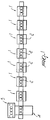
- the machine for forming and pressing powders particularly for producing ceramic tiles according to the present invention, comprises a plurality of filling stations 1 at which there are provided trays 2 which form one or more cavities inside them for organizing a charge of loose material.
- the trays are then transferred to a loading station, generally designated by the reference numeral 4, which sends the trays to a press 5, where the charge is transferred into the mold of the press without mutual movements among the components of the charge.
- the trays shown in figures 2 to 9 are used; said trays have a perimetric frame 10 provided by means of a tubular structure which forms a cavity 11 delimited, in a downward region, by a porous partition 12 which is constituted for example by a perforated metal plate 13 with a containment mesh 14 which lies above a suction chamber 15, in which spacing portions 16 are provided to allow to support the plate-like element in a perfectly level arrangement.
- a perimetric frame 10 provided by means of a tubular structure which forms a cavity 11 delimited, in a downward region, by a porous partition 12 which is constituted for example by a perforated metal plate 13 with a containment mesh 14 which lies above a suction chamber 15, in which spacing portions 16 are provided to allow to support the plate-like element in a perfectly level arrangement.
- the cavity 11 has the same shape as the mold of the press, so that the charge that is entirely organized inside the tray can be transferred into the mold without being altered.
- the porous partition is constituted by a stainless steel mesh 13 with openings measuring 180 to 250 microns and is fixed to, and tensioned on, the perforated metal plate by gluing or spot or intermittent welding or by means of screws.
- the mold is laterally provided with plates 18 which can slide vertically or are fixed, are coated with non-stick and/or wearproof materials and delimit, together with the porous bottom partition, the space meant for the loose material charge.
- This structure which is particularly light, advantageously but not exclusively uses light alloys, composite materials, alloy steels, sealing materials, elastomers, polymers, non-stick and wearproof coatings and magnetic locking of the lateral plates.
- the trays arranged in the various filling stations 1 follow a preloading path which arranges them sequentially in one or more filling stations arranged sequentially transversely or longitudinally or vertically or in a circular pattern proximate to the press; in each station, the upper cavity of the trays is filled entirely or partially, for example but not exclusively with the aid of screen-printing screens, perforated grids or templates that act as stencils, removable and fixed dividing elements, use of electrostatic systems, robotized tools provided or not with vision and image-recognition systems, microdosage units, vibrating units, air jets, suction nozzles or suckers, rods or mixers, or any other operation deemed suitable.
- the charge is precompacted by applying vacuum.
- the charge is mainly composed of paraspherical granules having different particle sizes and therefore the filling of the tray leaves the charge highly permeable to air owing to the empty spaces that remain between the spherical granules.
- the resulting precompaction reduces the ability of the granules to flow and facilitates precise transfer into the mold.
- the tray is overturned, as shown schematically in figure 5, and is then arranged above the mold 20 of the press 5, which has a lower punch 21 which is moved down gradually, so that the precompacted charge is transferred onto the lower punch of the press without undergoing any displacement or alteration of its components, so that the integrity of the formed pattern is maintained.
- the tray is moved away to perform another cycle.
- the essential element is the fact that the loose charge has been permanently organized, preformed and precompacted outside the mold of the press, so that the time required does not affect the production cycles of the machine.
- the tray designated by the reference numeral 30, which has a movable bottom 31 constituted by a thin plate of stainless steel which can be extracted from the guides 32 formed on the lateral plates 33; because of the limited thickness of the bottom plate, the fall of the charge is very short and its unsettling is likewise limited or negligible.
- the method used is therefore highly innovative with respect to the prior art, since the use of trays and filling stations allows to multiply the time and space available to load the mold without affecting the speed of the press.
- the time required for the entire cycle which includes loading the tray, precompacting the charge, the stroke for inserting the tray beneath the press and expelling the intact charge into the mold cavity, is significantly similar to the entire carriage cycle of an average conventional machine and can vary between 1.5 and 2.5 seconds.
- the active pressing cycle lasts approximately 3 seconds, during which the preloading region moves each tray by one step and replaces the empty tray with a full tray on the loading area, thus providing a cycle which lasts approximately 5 seconds with 12 beats per minute, as in conventional cycles.
- the materials employed, as well as the contingent shapes and dimensions may be any according to requirements.
Landscapes
- Engineering & Computer Science (AREA)
- Manufacturing & Machinery (AREA)
- Chemical & Material Sciences (AREA)
- Ceramic Engineering (AREA)
- Mechanical Engineering (AREA)
- Press-Shaping Or Shaping Using Conveyers (AREA)
- Preparation Of Clay, And Manufacture Of Mixtures Containing Clay Or Cement (AREA)
Applications Claiming Priority (2)
| Application Number | Priority Date | Filing Date | Title |
|---|---|---|---|
| ITMI970347 | 1997-02-18 | ||
| IT97MI000347A IT1290358B1 (it) | 1997-02-18 | 1997-02-18 | Macchina per la formatura e pressatura di polveri particolarmente per la produzione di piastrelle ceramiche nonche' procedimento per la |
Publications (1)
| Publication Number | Publication Date |
|---|---|
| EP0858873A1 true EP0858873A1 (fr) | 1998-08-19 |
Family
ID=11376069
Family Applications (1)
| Application Number | Title | Priority Date | Filing Date |
|---|---|---|---|
| EP98102127A Withdrawn EP0858873A1 (fr) | 1997-02-18 | 1998-02-06 | Dispositif pour le pressage de poudres, en particulier dispositif et procédé pour le pressage de carreaux en céramique |
Country Status (2)
| Country | Link |
|---|---|
| EP (1) | EP0858873A1 (fr) |
| IT (1) | IT1290358B1 (fr) |
Cited By (4)
| Publication number | Priority date | Publication date | Assignee | Title |
|---|---|---|---|---|
| EP0997248A3 (fr) * | 1998-09-28 | 2000-12-20 | Carlo Antonio Camorani | Procédé et dispositif pour transférer un matériau granuleux |
| US6391236B1 (en) * | 1997-06-10 | 2002-05-21 | Alberto Franceschini | Process and plant for forming ceramic tiles and the like |
| WO2003045649A1 (fr) * | 2001-11-28 | 2003-06-05 | Delphin Italia S.R.L. | Procede et dispositif destines a presser des carreaux de ceramique |
| WO2025248424A1 (fr) | 2024-05-31 | 2025-12-04 | Sacmi Cooperativa Meccanici Imola Societa' Cooperativa | Installation et procédé de production de produits céramiques |
Citations (6)
| Publication number | Priority date | Publication date | Assignee | Title |
|---|---|---|---|---|
| US3970223A (en) * | 1974-04-04 | 1976-07-20 | Longinotti S.P.A. | Material metering units |
| FR2444543A1 (fr) * | 1978-12-21 | 1980-07-18 | Longinotti Spa | Appareillage destine a charger une sous-couche dans un moule pour la fabrication de carreaux de ciment et utilisations equivalentes |
| DE3941346A1 (de) * | 1988-12-15 | 1990-06-21 | Murata Manufacturing Co | Verfahren zur herstellung von mehrschichtkondensatoren |
| EP0444730A2 (fr) * | 1990-02-26 | 1991-09-04 | L.B. Officine Meccaniche S.P.A. | Chariot de remplissage double pour l'alimentation de moules pour céramique, en particulier pour la fabrication de carreaux pressés émaillés |
| EP0693352A2 (fr) * | 1994-07-21 | 1996-01-24 | L.B. Engineering S.R.L. | Dispositif pour l'alimentation d'un chariot de remplissage de moules lors de la fabrication de carreaux de céramique |
| WO1996015888A1 (fr) * | 1994-11-22 | 1996-05-30 | Carlo Antonio Camorani | Procede de compactage de poudres et appareil associe |
-
1997
- 1997-02-18 IT IT97MI000347A patent/IT1290358B1/it active IP Right Grant
-
1998
- 1998-02-06 EP EP98102127A patent/EP0858873A1/fr not_active Withdrawn
Patent Citations (6)
| Publication number | Priority date | Publication date | Assignee | Title |
|---|---|---|---|---|
| US3970223A (en) * | 1974-04-04 | 1976-07-20 | Longinotti S.P.A. | Material metering units |
| FR2444543A1 (fr) * | 1978-12-21 | 1980-07-18 | Longinotti Spa | Appareillage destine a charger une sous-couche dans un moule pour la fabrication de carreaux de ciment et utilisations equivalentes |
| DE3941346A1 (de) * | 1988-12-15 | 1990-06-21 | Murata Manufacturing Co | Verfahren zur herstellung von mehrschichtkondensatoren |
| EP0444730A2 (fr) * | 1990-02-26 | 1991-09-04 | L.B. Officine Meccaniche S.P.A. | Chariot de remplissage double pour l'alimentation de moules pour céramique, en particulier pour la fabrication de carreaux pressés émaillés |
| EP0693352A2 (fr) * | 1994-07-21 | 1996-01-24 | L.B. Engineering S.R.L. | Dispositif pour l'alimentation d'un chariot de remplissage de moules lors de la fabrication de carreaux de céramique |
| WO1996015888A1 (fr) * | 1994-11-22 | 1996-05-30 | Carlo Antonio Camorani | Procede de compactage de poudres et appareil associe |
Cited By (4)
| Publication number | Priority date | Publication date | Assignee | Title |
|---|---|---|---|---|
| US6391236B1 (en) * | 1997-06-10 | 2002-05-21 | Alberto Franceschini | Process and plant for forming ceramic tiles and the like |
| EP0997248A3 (fr) * | 1998-09-28 | 2000-12-20 | Carlo Antonio Camorani | Procédé et dispositif pour transférer un matériau granuleux |
| WO2003045649A1 (fr) * | 2001-11-28 | 2003-06-05 | Delphin Italia S.R.L. | Procede et dispositif destines a presser des carreaux de ceramique |
| WO2025248424A1 (fr) | 2024-05-31 | 2025-12-04 | Sacmi Cooperativa Meccanici Imola Societa' Cooperativa | Installation et procédé de production de produits céramiques |
Also Published As
| Publication number | Publication date |
|---|---|
| IT1290358B1 (it) | 1998-10-22 |
| ITMI970347A1 (it) | 1998-08-18 |
Similar Documents
| Publication | Publication Date | Title |
|---|---|---|
| CN110153411B (zh) | 基于电阻加热的点阵式铺粉3d打印装置与打印方法 | |
| US20200282596A1 (en) | Interlayer mixing apparatus for texturing man-made stone slabs | |
| DE69738589T2 (de) | Verfahren zum Pressen von pulverförmigen Material | |
| EP0422287B1 (fr) | Appareil pour la fabrication automatisée de gâteaux ou produits similaires | |
| RU2018109736A (ru) | Система и аппаратный агрегат трехмерной печати | |
| EP0793565A1 (fr) | Procede de compactage de poudres et appareil associe | |
| US7866352B2 (en) | Filling method and filling apparatus of powder-particle material in compression molding | |
| US4501714A (en) | Method for molding a ceramic article | |
| EP0822044B1 (fr) | Dispositif d'alimentation pour moules dans les presses pour la fabrication de carreaux en céramique émaillés pressés et moyens de mise en oeuvre correspondants | |
| EP0569070B1 (fr) | Moule pour la fabrication d'éléments en céramiques, en particulier de carreaux pressés émaillés et moyens d'alimentation de ce moule | |
| EP0444730B1 (fr) | Chariot de remplissage double pour l'alimentation de moules pour céramique, en particulier pour la fabrication de carreaux pressés émaillés | |
| EP0858873A1 (fr) | Dispositif pour le pressage de poudres, en particulier dispositif et procédé pour le pressage de carreaux en céramique | |
| US3970223A (en) | Material metering units | |
| EP0873832A1 (fr) | Dispositif pour le pressage de carreaux en céramique comportant deux couches | |
| WO2005025829A1 (fr) | Procede et installation pour former des plaques ou des dalles ceramiques | |
| EP0940234B1 (fr) | Méthode et dispositif pour la fabrication de carreaux en céramique | |
| US1792844A (en) | Machine for making artificial building stone | |
| RS66029B1 (sr) | Mašina za presovanje tableta | |
| EP0997248B1 (fr) | Procédé et dispositif pour transférer un matériau granuleux | |
| EP0909621B1 (fr) | Méthode pour l'obtention et la décoration d'ébauches non cuites de carreaux en céramique avant le pressage et dispositif pour la mise en oeuvre du procédé | |
| EP0569069B1 (fr) | Moule pour la fabrication de carreaux en céramique et moyens d'alimentation de ce moule | |
| EP0468577B1 (fr) | Installation à productivité élevée pour la fabrication de carreaux en céramique en général | |
| DE2550474A1 (de) | Vorrichtung zum automatischen herstellen keramischer dekorfliesenformlinge | |
| EP1510312A2 (fr) | Procédé et dispositif pour fabriquer un produit décoré, et produit ainsi décoré | |
| EP1256428A2 (fr) | Procédé pour le remplissage des moules d'une presse utilisée dans la fabrication de carreaux en céramique, moyens de mise en oeuvre correspondants et carreaux ainsi fabriqués |
Legal Events
| Date | Code | Title | Description |
|---|---|---|---|
| PUAI | Public reference made under article 153(3) epc to a published international application that has entered the european phase |
Free format text: ORIGINAL CODE: 0009012 |
|
| AK | Designated contracting states |
Kind code of ref document: A1 Designated state(s): AT BE CH DE DK ES FI FR GB GR IE IT LI LU MC NL PT SE |
|
| AX | Request for extension of the european patent |
Free format text: AL;LT;LV;MK;RO;SI |
|
| STAA | Information on the status of an ep patent application or granted ep patent |
Free format text: STATUS: THE APPLICATION HAS BEEN WITHDRAWN |
|
| AKX | Designation fees paid | ||
| RBV | Designated contracting states (corrected) | ||
| 18W | Application withdrawn |
Withdrawal date: 19990308 |