EP0858931A2 - Dispositif pour commander la portée des phases d'un véhicule - Google Patents
Dispositif pour commander la portée des phases d'un véhicule Download PDFInfo
- Publication number
- EP0858931A2 EP0858931A2 EP97119873A EP97119873A EP0858931A2 EP 0858931 A2 EP0858931 A2 EP 0858931A2 EP 97119873 A EP97119873 A EP 97119873A EP 97119873 A EP97119873 A EP 97119873A EP 0858931 A2 EP0858931 A2 EP 0858931A2
- Authority
- EP
- European Patent Office
- Prior art keywords
- radiation
- emitted
- vehicle
- headlight
- evaluation
- Prior art date
- Legal status (The legal status is an assumption and is not a legal conclusion. Google has not performed a legal analysis and makes no representation as to the accuracy of the status listed.)
- Granted
Links
Images


Classifications
-
- B—PERFORMING OPERATIONS; TRANSPORTING
- B60—VEHICLES IN GENERAL
- B60Q—ARRANGEMENT OF SIGNALLING OR LIGHTING DEVICES, THE MOUNTING OR SUPPORTING THEREOF OR CIRCUITS THEREFOR, FOR VEHICLES IN GENERAL
- B60Q1/00—Arrangement of optical signalling or lighting devices, the mounting or supporting thereof or circuits therefor
- B60Q1/02—Arrangement of optical signalling or lighting devices, the mounting or supporting thereof or circuits therefor the devices being primarily intended to illuminate the way ahead or to illuminate other areas of way or environments
- B60Q1/04—Arrangement of optical signalling or lighting devices, the mounting or supporting thereof or circuits therefor the devices being primarily intended to illuminate the way ahead or to illuminate other areas of way or environments the devices being headlights
- B60Q1/14—Arrangement of optical signalling or lighting devices, the mounting or supporting thereof or circuits therefor the devices being primarily intended to illuminate the way ahead or to illuminate other areas of way or environments the devices being headlights having dimming means
- B60Q1/1415—Dimming circuits
- B60Q1/1423—Automatic dimming circuits, i.e. switching between high beam and low beam due to change of ambient light or light level in road traffic
-
- B—PERFORMING OPERATIONS; TRANSPORTING
- B60—VEHICLES IN GENERAL
- B60Q—ARRANGEMENT OF SIGNALLING OR LIGHTING DEVICES, THE MOUNTING OR SUPPORTING THEREOF OR CIRCUITS THEREFOR, FOR VEHICLES IN GENERAL
- B60Q1/00—Arrangement of optical signalling or lighting devices, the mounting or supporting thereof or circuits therefor
- B60Q1/0017—Devices integrating an element dedicated to another function
- B60Q1/0023—Devices integrating an element dedicated to another function the element being a sensor, e.g. distance sensor, camera
-
- B—PERFORMING OPERATIONS; TRANSPORTING
- B60—VEHICLES IN GENERAL
- B60Q—ARRANGEMENT OF SIGNALLING OR LIGHTING DEVICES, THE MOUNTING OR SUPPORTING THEREOF OR CIRCUITS THEREFOR, FOR VEHICLES IN GENERAL
- B60Q2300/00—Indexing codes for automatically adjustable headlamps or automatically dimmable headlamps
- B60Q2300/10—Indexing codes relating to particular vehicle conditions
- B60Q2300/13—Attitude of the vehicle body
- B60Q2300/132—Pitch
-
- B—PERFORMING OPERATIONS; TRANSPORTING
- B60—VEHICLES IN GENERAL
- B60Q—ARRANGEMENT OF SIGNALLING OR LIGHTING DEVICES, THE MOUNTING OR SUPPORTING THEREOF OR CIRCUITS THEREFOR, FOR VEHICLES IN GENERAL
- B60Q2300/00—Indexing codes for automatically adjustable headlamps or automatically dimmable headlamps
- B60Q2300/10—Indexing codes relating to particular vehicle conditions
- B60Q2300/13—Attitude of the vehicle body
- B60Q2300/136—Roll
Definitions
- the invention relates to a control device the range of headlights of vehicles after the Genus of claim 1.
- Such a device is described in DE 43 41 409 A1 known.
- This device shows the headlights assigned adjustment devices for adjusting the Headlight range.
- the facility points also a transmission device through which a Radiation beam is emitted, which is an area in front of the Irradiated vehicle. If the inclination of the Vehicle changes the headlight range with the vehicle connected headlights, which is too large a headlight range dazzling oncoming traffic or if there is too little Headlight range to an insufficient viewing range of the Vehicle driver leads. If the Vehicle inclination also changes the distance of the irradiated Area from the vehicle.
- a sensor device Device is detected from the area of retroreflected radiation and this is evaluated by an evaluation device.
- the retroreflected Radiation the location of the area, especially its distance determined by the vehicle and a signal is generated for this purpose with a when the headlight range is set correctly existing target signal is compared.
- existing Deviation between the current signal and the target signal the adjustment devices to eliminate the Deviation controlled.
- the Headlamp leveling device is a certain Inaccuracy in the setting of the light range, because of the distance of the irradiated area from the vehicle not only changes with the vehicle inclination but also with the change the height of the vehicle, i.e. its entry or exit Suspension at the installation site of the transmitter. This can however, are not recognized by the evaluation device, so that the headlight range may not be correct here is set.
- the inventive device for regulating Headlight range of vehicles has in contrast, the advantage that the light range with a larger Accuracy can be set because the respective Distance of the irradiated area next to the Change in inclination of the vehicle also from the change in height depends on the evaluated ratio of these Distances only from the change in inclination is dependent.
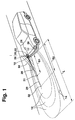
- FIG 1 shows a simplified illustration Representation of a vehicle with headlights and one Device for regulating the headlight range
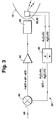
- 2 shows the vehicle in a vertical longitudinal section
- FIG 3 shows a simplified circuit diagram of the control device the headlight range
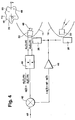
- Figure 4 shows the vehicle with the Headlamp leveling device according to a first Embodiment
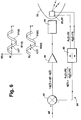
- Figure 5 is a simplified circuit diagram the headlamp leveling device according to a second Embodiment
- Figure 6 is a simplified Circuit diagram and the headlamp leveling device according to a third embodiment.
- a vehicle shown in Figure 1 in particular a Motor vehicle, has in a known manner at its front end two headlights located near the sides of the vehicle 10.11 on. It can be provided that the headlights 10,11 only serve to generate the low beam or alternatively to the optional generation of the low beam and of the high beam. If necessary, the headlights 10, 11 also serve to generate other light beams, for example a fog light. In the operating position for low beam are from the headlights 10.11 Beam of light 12 emitted through which the front of the vehicle surrounding area, including the road 14, illuminated will. The light beams 12 in FIG. 1 are based on several Lines of the same illuminance are indicated.
- the Beam 12 has an upper light-dark limit, which causes that the road 14 only up to a certain distance L is illuminated in front of the vehicle.
- the range L represents the light range of the headlights 10, 11 represents a changing loading of the vehicle or during the Driving the vehicle, for example, as a result of braking and / or Accelerations or bumps in the road Changes in inclination of the vehicle that occurs Headlight range 10.11 with the vehicle are connected, and the position of the light-dark boundary changes. Either the apron of the carriageway 14 is no longer adequately illuminated when the lighting range becomes smaller, or oncoming traffic is dazzled when the Headlight range increases.
- Device for regulating the lighting range provided by which regardless of changes in vehicle inclination Headlight range can be kept constant.
- the device for regulating the lighting range can with the Operation of the headlights 10.11 are activated or alternatively, constantly while the vehicle is operating be activated.
- the headlamp leveling device has a transmission device 20, a sensor device 22, a Evaluation device 24 and the headlights 10, 11 associated adjusting devices 26 through which the Headlight range 10.11 can be adjusted.
- the transmitting device 20 can be at the front end of the Be arranged vehicle, for example in the area of a Headlights 10.11.
- the transmission device is preferably 20 integrated into a headlight 10, 11, the Transmitter 20 at one by the adjusting device 26 caused adjustment of the headlight range is also adjusted.
- Be through the transmitter 20 emitted at least two radiation beams 28, 29 which are on the road 14 is directed in front of the vehicle and are concentrated as much as possible, so that only small ones Areas in the form of spots 31, 32 of the road 14 are irradiated will.
- the two of the radiation beams 28, 29 irradiated areas 31, 32 have different distances from the vehicle, the spot 31 being a distance s1 and Spot 32 has a distance s2.
- the two Radiation beams 28, 29 preferably go at least approximately from the same origin and run in one common vertical plane 34 so that the areas 31,32 in the vertical plane 34 the different distances s1, s2 have, but both lie in the vertical plane 34.
- the sensor device 22 detects from the Spots 31,32 reflected radiation and there will be Signals for the distance d1 and d2 of spots 31, 32 from the Transmitting device 20 or the sensor device 22 is formed.
- the sensor device 22 can be placed anywhere on the vehicle be arranged, the arrangement being such that of the Spots 31.32 reflected radiation through the Sensor device 22 can be detected.
- the Sensor device 22 can in particular in the area one of the headlights 10, 11 may be arranged and preferably integrated into one of the headlights 10, 11 be an integration in the same headlight as the transmitter 20 or in the other headlight can be provided.
- the in the sensor device 22nd generated signals are sent to the evaluation device 24 fed and processed in this.
- the evaluation device 24 has a unit 40 in which a signal for the ratio q ( ⁇ ) of the distance d1 to the distance d2 is formed.
- the signal for the ratio q ( ⁇ ) is fed to a comparator 42, by means of which the current signal for the ratio q ( ⁇ ) is compared with a predetermined target signal for a target ratio q0.
- the target signal for the target ratio q0 results when the headlight range is set correctly, in which the spots 31, 32 are located at certain distances from the vehicle.
- FIG. 2 is a first Cartesian coordinate system with a horizontal axis Z0 and a vertical axis X0 shown, which is fixed with respect to the road 14.
- a second Cartesian coordinate system has one horizontal axis Z and a vertical axis X, where this coordinate system is fixed with respect to the vehicle and its position changes with the position of the vehicle.
- the vehicle has one Inclination, which is determined by the angle ⁇ between the axes Z0 and Z and between the axes X0 and X is clarified.
- Radiation beams 28, 29 are inclined to the Z axis, wherein the radiation beam 28 at an angle ⁇ 1 to the Z axis runs inclined and the radiation beam 29 under one Angle ⁇ 2 is inclined to the Z axis.
- the spot 31 is in a distance d1 from the transmitter 20 and with this sensor device 22 integrated in the headlight 10 remotely located and the spot 32 is at a distance d2 arranged.
- the load on the vehicle changes or when braking or occurring during the journey Acceleration processes and when driving over Uneven road surface occurs a change in the angle of inclination ⁇ of the vehicle with which the distances d1 and d2 of spots 31, 32 change. In these processes occurs however, also a change in the height h of the mounting location Transmission device 20 and the sensor device 22 on Vehicle relative to the road 14, which is also a Change the distances d1 and d2 of spots 31 and 32 leads.
- the distances d1 and d2 depend not only on the angle of inclination but also on the change in height h ( ⁇ h).
- the ratio q ( ⁇ ) can be determined and be compared with the target ratio q0 and the Difference ⁇ q ( ⁇ ) can be formed.
- both transmission device 20 and a sensor device 22 with associated Evaluation device 24 are provided, for example can be integrated in a headlight 10.
- the Evaluation device 24 is also with the Adjustment device 26 of the other headlight 11 connected, so that the headlight range accordingly is set. It is assumed that both Headlights 10.11 initially the same basic setting Have lighting range, based on the one setting the lighting range occurs. Alternatively, it can also be provided be that in both headlights 10.11 one each Transmitter 20 and a sensor device 22 with associated evaluation device 24 is provided. In this Fall need the basic settings of the light range of the two headlights 10, 11 do not match.
- the transmission device 20 of those described above Headlamp leveling device can for example a first embodiment as shown in Figure 4 emit electromagnetic radiation beams 28, 29, whereby this light in the visible or invisible Wavelength range can be.
- the sensor device 22 is accordingly as optoelectronic Designed sensor device and has one or more for the radiation emitted by the transmitter 20 sensitive elements 46.
- the sensor device 22 is arranged on the vehicle at a distance from the transmission device 20, so that the optical axes of the transmitter 20 and the Sensor device 22 differ from each other.
- the transmitting device 20 in a headlight 10 and the sensor device 22 in the other headlight 11 be integrated.
- the elements 46 of the sensor device 22 can alternatively as photodiodes, photocells or as CCD cells (Charge-coupled device) that are linear or are arranged in a matrix.
- the sensor device 22 also has imaging optics 48 through which incident radiation is directed onto the elements 46, where the radiation depends on its direction of incidence different elements 46 hits.
- the Sensor device 22 also as a position sensor, for example in the form of a PSD (Position Sensing Device) be executed.
- PSD Position Sensing Device
- the Sensor device 22 distributed a plurality of matrix-like arranged elements 46 on.
- the spots 31,32 are at this version as pixels 49.50 on individual elements 46 mapped in the sensor device 22.
- the locations of the Spots representing 31.32 pixels 49.50 in the Sensor device 22 are a measure of the distances d1 and d2 of spots 31.32.
- the evaluation device 24 a signal for the Ratio q ( ⁇ ) for the distances d1 and d2 formed signals formed and this is with the predetermined target signal compared and with existing Deviation, the adjustment devices 26 are controlled.
- the Radiation beams 28,29 are thereby Transmitting device 20 is not continuously transmitted, but pulsed so that each for a radiation pulse above evaluation can be performed.
- the Transmitting device 20 can be, for example, a or several light-emitting diodes, in particular laser diodes, as Have radiation sources.
- Another alternative approach to determining the Distances d1 and d2 of spots 31, 32 consists in that the transmitter 20 with the radiation beam 28,29 emits a phase modulation, the intensity of the Radiation bundles 28, 29 at a certain frequency changes. Retroreflected at spots 31.32 and from the Sensor device 22 has received radiation also a phase modulation, but opposite the phase modulation by the transmitter 20 emitted radiation beam 28, 29 is shifted.
- the Difference in phase modulations from that Sensor device 22 received radiation compared to Phase modulations of the emitted radiation beams 28, 29 is a measure of the time between transmission and Receiving the radiation and thus a measure of the distances d1 and d2 of spots 31.32.
- FIG. 6 shows the course of the intensity I02 (t) of the second radiation beam 29 and the course of the Intensity I12 (t) of the rays reflected by the spot 32 Radiation shown. There is one between them There is a phase difference ⁇ bat2.
- phase differences ⁇ 1 and ⁇ 2 are proportional to the distances d1 and d2 of spots 31 and 32, with those in sensor device 22 thereby obtained from the differences in the phase modulations Signals for the distances d1 and d2 then again as explained above in the evaluation device 24 are processed.
- Embodiment can by the transmitting device 20th emitted radiation bundle 28,29 electromagnetic Radiation, such as light in the visible or invisible wavelength range.
- the Radiation bundle 28,29 also electromagnetic radiation in Be in the form of microwaves.
- the usage Electromagnetic radiation has the advantage that the The distances d1 and d2 can be determined very quickly may, 1ms or less may be sufficient for this, and thus the regulation of the headlight range accordingly quickly can take place and also with short-term changes of the The headlight range can be set correctly can.
- the radiation beams 28, 29 also sound waves, especially ultrasonic waves.
Landscapes
- Engineering & Computer Science (AREA)
- Mechanical Engineering (AREA)
- Lighting Device Outwards From Vehicle And Optical Signal (AREA)
Applications Claiming Priority (2)
| Application Number | Priority Date | Filing Date | Title |
|---|---|---|---|
| DE19704466 | 1997-02-06 | ||
| DE19704466A DE19704466A1 (de) | 1997-02-06 | 1997-02-06 | Einrichtung zur Regelung der Leuchtweite von Scheinwerfern von Fahrzeugen |
Publications (3)
| Publication Number | Publication Date |
|---|---|
| EP0858931A2 true EP0858931A2 (fr) | 1998-08-19 |
| EP0858931A3 EP0858931A3 (fr) | 1998-12-02 |
| EP0858931B1 EP0858931B1 (fr) | 2003-05-07 |
Family
ID=7819465
Family Applications (1)
| Application Number | Title | Priority Date | Filing Date |
|---|---|---|---|
| EP97119873A Expired - Lifetime EP0858931B1 (fr) | 1997-02-06 | 1997-11-13 | Dispositif pour commander la portée des phases d'un véhicule |
Country Status (4)
| Country | Link |
|---|---|
| US (1) | US6130506A (fr) |
| EP (1) | EP0858931B1 (fr) |
| JP (1) | JPH10217844A (fr) |
| DE (2) | DE19704466A1 (fr) |
Cited By (1)
| Publication number | Priority date | Publication date | Assignee | Title |
|---|---|---|---|---|
| EP1270325A3 (fr) * | 2001-06-26 | 2005-07-06 | Hella KGaA Hueck & Co. | Phare de véhicule |
Families Citing this family (31)
| Publication number | Priority date | Publication date | Assignee | Title |
|---|---|---|---|---|
| DE19902015A1 (de) * | 1999-01-20 | 2000-07-27 | Porsche Ag | Anordnung zur Anpassung des Beleuchtungssystems an einem Kraftfahrzeug |
| DE19950504A1 (de) * | 1999-10-20 | 2001-05-10 | Porsche Ag | Verfahren und Vorrichtung zur Steuerung der Lichtvertielung einer Scheinwerferanordnung eines Fahrzeuges |
| JP2001347882A (ja) * | 2000-04-03 | 2001-12-18 | Denso Corp | 車両用前照灯光軸方向自動調整装置 |
| DE10054606A1 (de) * | 2000-11-04 | 2002-05-08 | Hella Kg Hueck & Co | Verfahren und Vorrichtung zur Leuchtweitenregelung der Scheinwerfer eines Kraftfahrzeugs |
| DE10054614A1 (de) * | 2000-11-04 | 2002-05-08 | Hella Kg Hueck & Co | Einrichtung und Verfahren zur Regelung der Leuchtweite von Scheinwerfern eines Kraftfahrzeugs |
| US6981787B2 (en) * | 2001-12-18 | 2006-01-03 | Visteon Global Technologies, Inc. | Electric control for automobile headlights |
| JP4757427B2 (ja) * | 2002-02-15 | 2011-08-24 | 三菱電機株式会社 | 傾斜角度測定装置 |
| JP2003307564A (ja) * | 2002-02-15 | 2003-10-31 | Mitsubishi Electric Corp | 傾斜角度測定装置 |
| JP2004168179A (ja) * | 2002-11-20 | 2004-06-17 | Koito Mfg Co Ltd | 車両用前照灯の照射方向制御装置 |
| JP2004276824A (ja) * | 2003-03-18 | 2004-10-07 | Mitsubishi Fuso Truck & Bus Corp | 車両用ヘッドランプの光軸調整装置 |
| JP2004276825A (ja) | 2003-03-18 | 2004-10-07 | Mitsubishi Fuso Truck & Bus Corp | 車両用ヘッドランプの光軸調整装置 |
| DE102006044794A1 (de) * | 2006-09-14 | 2008-03-27 | Schefenacker Vision Systems Germany Gmbh | Fahrzeugbasiertes Lidar-System |
| DE102007036081A1 (de) * | 2007-08-01 | 2009-02-05 | GM Global Technology Operations, Inc., Detroit | Beleuchtungseinrichtung für ein Kraftfahrzeug und Verfahren zur Steuerung einer Leuchte |
| DE102010044263A1 (de) * | 2010-09-03 | 2012-03-08 | Daimler Ag | Vorrichtung und Verfahren zur Steuerung eines aktiven Fahrwerks eines Fahrzeugs |
| DE102010044557A1 (de) | 2010-09-07 | 2012-03-08 | Valeo Schalter Und Sensoren Gmbh | Verfahren und Vorrichtung zum automatischen Einstellen einer Ausrichtung eines von einem Scheinwerfer eines Kraftfahrzeugs abgegebenen Lichts |
| DE102010044558A1 (de) * | 2010-09-07 | 2012-03-08 | Valeo Schalter Und Sensoren Gmbh | Verfahren und Vorrichtung zum automatischen Einstellen einer Ausrichtung eines von einem Scheinwerfer eines Kraftfahrzeugs abgegebenen Lichts |
| RU2546547C1 (ru) * | 2011-04-13 | 2015-04-10 | Ниссан Мотор Ко., Лтд. | Устройство помощи при вождении и способ обнаружения транспортного средства рядом с ним |
| CN103101472A (zh) * | 2011-11-14 | 2013-05-15 | 褚凤红 | 机动车导航装置 |
| SE536851C2 (sv) * | 2013-01-23 | 2014-10-07 | Scania Cv Ab | Bestämning av ett fordons lutning |
| DE102013003459A1 (de) * | 2013-03-01 | 2014-09-04 | GM Global Technology Operations LLC (n. d. Gesetzen des Staates Delaware) | Verfahren zur Leuchtweitenregelung eines Fahrzeugscheinwerfers |
| DE102013219097A1 (de) * | 2013-09-23 | 2015-03-26 | Hella Kgaa Hueck & Co. | Verfahren zur Steuerung einer Ausleuchtung einer Fahrspur |
| EP2860704B1 (fr) * | 2013-10-10 | 2016-04-27 | U-Shin France SAS | Procédé d'ouverture d'un panneau mobile de véhicule automobile et dispositif de commande d'ouverture correspondant |
| DE102014216545B4 (de) * | 2014-08-20 | 2017-04-27 | Automotive Lighting Reutlingen Gmbh | Scheinwerfervorrichtung mit rechts und links unterschiedlichen Fernlichtmodulen |
| FR3036181B1 (fr) * | 2015-05-11 | 2019-08-16 | Valeo Schalter Und Sensoren Gmbh | Vehicule automobile equipe de teledetecteurs par laser. |
| DE102015210927A1 (de) | 2015-06-15 | 2016-12-15 | Automotive Lighting Reutlingen Gmbh | Autonomer Aktor zur Variation einer Lichtverteilung einer Beleuchtungseinrichtung eines Kraftfahrzeugs |
| US10011182B2 (en) * | 2016-03-24 | 2018-07-03 | Ford Global Technologies, Llc | Inductive charger alignment systems for vehicles |
| JP6351907B2 (ja) * | 2016-03-30 | 2018-07-04 | 三菱電機株式会社 | 光軸制御装置 |
| US11273752B2 (en) * | 2019-04-12 | 2022-03-15 | Caterpillar Paving Products Inc. | Illumination control system for mobile machines |
| DE102019123397A1 (de) * | 2019-09-02 | 2021-03-04 | HELLA GmbH & Co. KGaA | Beleuchtungsvorrichtung für ein Kraftfahrzeug, insbesondere Scheinwerfer |
| DE102021002775B3 (de) * | 2021-05-28 | 2022-08-04 | Mercedes-Benz Group AG | Verfahren zur Anpassung eines Scheinwerfersystems |
| CN113895347A (zh) * | 2021-11-24 | 2022-01-07 | 斯沃博达汽车电子(昆山)有限公司 | 一种基于车轮传感器的车灯角度调节系统 |
Citations (1)
| Publication number | Priority date | Publication date | Assignee | Title |
|---|---|---|---|---|
| DE4341409A1 (de) | 1993-12-04 | 1995-06-08 | Bosch Gmbh Robert | Einrichtung zur Regelung der Leuchtweite von Scheinwerfern von Kraftfahrzeugen |
Family Cites Families (7)
| Publication number | Priority date | Publication date | Assignee | Title |
|---|---|---|---|---|
| FR2458426A1 (fr) * | 1979-06-07 | 1981-01-02 | Ducellier & Cie | Dispositif de reglage automatique de projecteurs |
| CA1235773A (fr) * | 1983-12-23 | 1988-04-26 | Shigeto Nakayama | Detecteur d'etat d'une chaussee |
| FR2574725B1 (fr) * | 1984-12-14 | 1987-03-20 | Cibie Projecteurs | Correcteur automatique de la direction des projecteurs lors des variations d'assiette d'un vehicule |
| JPH0825417B2 (ja) * | 1987-08-17 | 1996-03-13 | 株式会社小糸製作所 | 二輪車輌用前照灯の照射角修正装置 |
| DE4122531C2 (de) * | 1991-07-08 | 2001-06-07 | Bosch Gmbh Robert | Einrichtung zur Regelung der Leuchtweite von Scheinwerfern von Kraftfahrzeugen |
| FR2707390B1 (fr) * | 1993-07-09 | 1995-09-29 | Valeo Vision | Dispositif indicateur d'assiette pour véhicule automobile. |
| US5633710A (en) * | 1995-10-04 | 1997-05-27 | Egs Inc. | System for self-aligning vehicle headlamps |
-
1997
- 1997-02-06 DE DE19704466A patent/DE19704466A1/de not_active Withdrawn
- 1997-11-13 DE DE59710038T patent/DE59710038D1/de not_active Expired - Lifetime
- 1997-11-13 EP EP97119873A patent/EP0858931B1/fr not_active Expired - Lifetime
-
1998
- 1998-02-03 JP JP2169698A patent/JPH10217844A/ja active Pending
- 1998-02-06 US US09/020,007 patent/US6130506A/en not_active Expired - Fee Related
Patent Citations (1)
| Publication number | Priority date | Publication date | Assignee | Title |
|---|---|---|---|---|
| DE4341409A1 (de) | 1993-12-04 | 1995-06-08 | Bosch Gmbh Robert | Einrichtung zur Regelung der Leuchtweite von Scheinwerfern von Kraftfahrzeugen |
Cited By (1)
| Publication number | Priority date | Publication date | Assignee | Title |
|---|---|---|---|---|
| EP1270325A3 (fr) * | 2001-06-26 | 2005-07-06 | Hella KGaA Hueck & Co. | Phare de véhicule |
Also Published As
| Publication number | Publication date |
|---|---|
| EP0858931B1 (fr) | 2003-05-07 |
| EP0858931A3 (fr) | 1998-12-02 |
| DE59710038D1 (de) | 2003-06-12 |
| US6130506A (en) | 2000-10-10 |
| JPH10217844A (ja) | 1998-08-18 |
| DE19704466A1 (de) | 1998-08-13 |
Similar Documents
| Publication | Publication Date | Title |
|---|---|---|
| EP0858931B1 (fr) | Dispositif pour commander la portée des phases d'un véhicule | |
| EP3809157B1 (fr) | Capteur optoélectronique de mesure de distance et procédé de détection d'un objet cible | |
| DE19733491B4 (de) | Verfahren zur Zielsuche für geodätische Geräte | |
| DE3447015C2 (de) | Vorrichtung zum Erfassen des Zustands einer Straßenoberfläche im Bereich eines Straßenfahrzeugs | |
| EP1001274B1 (fr) | Procédé et dispositif pour le simbleautage d'un cheminement de rayonnement d'un capteur rayonnant | |
| DE19704427A1 (de) | Einrichtung zur Regelung der Leuchtweite von Scheinwerfern von Fahrzeugen | |
| DE3403082C2 (fr) | ||
| EP1478942A1 (fr) | Detecteur radar pour vehicules | |
| DE2409563A1 (de) | Verfahren und vorrichtung fuer die zielfuehrung | |
| EP1927014B1 (fr) | Appareil de mesure electrooptique | |
| EP3347732A1 (fr) | Dispositif de balayage laser pour véhicules automobiles | |
| EP0396865A2 (fr) | Radar optique | |
| DE102017116597A1 (de) | Sendevorrichtung für ein abtastendes optisches Detektionssystem eines Fahrzeugs, Detektionssystem, Fahrerassistenzsystem, Verfahren zur Steuerung einer Strahlrichtung eines optischen Sendesignals | |
| DE19815985A1 (de) | Einrichtung zur Einstellung der Richtung des von wenigstens einem Scheinwerfer eines Fahrzeugs ausgesandten Lichtbündels | |
| EP1831717B1 (fr) | Detecteur a zone d'action immediate optique | |
| EP3519858B1 (fr) | Unité de balayage d'un dispositif de réception et d'émission optique d'un dispositif de détection optique d'un véhicule | |
| DE60300794T2 (de) | Vorrichtung und Verfahren zum Einstellen der Orientierung von wenigstens einem Fahrzeugscheinwerfer | |
| EP0378751B1 (fr) | Dispositif de mesure de hauteur à laser | |
| DE2850743C3 (de) | Verfahren und Vorrichtung zur Messung der Abweichung des Sendestrahls von der optischen Achse des Empfangsteleskops bei einem Lidargerät | |
| DE3207382C2 (de) | Abtastender Laserentfernungsmesser | |
| DE4427724C2 (de) | Verfahren und Vorrichtung zum Messen einer winkelabhängigen Größe | |
| WO2022058155A1 (fr) | Procédé destiné à la détection d'objets et dispositif de détection | |
| DE10356418A1 (de) | Verfahren zur Positionsverfolgung von beweglichen Objekten und Positionsverfolgungssystem | |
| DE102010044558A1 (de) | Verfahren und Vorrichtung zum automatischen Einstellen einer Ausrichtung eines von einem Scheinwerfer eines Kraftfahrzeugs abgegebenen Lichts | |
| EP4441524B1 (fr) | Procédé de fonctionnement d'un système lidar, système lidar et véhicule comprenant au moins un système lidar |
Legal Events
| Date | Code | Title | Description |
|---|---|---|---|
| PUAI | Public reference made under article 153(3) epc to a published international application that has entered the european phase |
Free format text: ORIGINAL CODE: 0009012 |
|
| AK | Designated contracting states |
Kind code of ref document: A2 Designated state(s): DE FR GB IT |
|
| PUAL | Search report despatched |
Free format text: ORIGINAL CODE: 0009013 |
|
| AK | Designated contracting states |
Kind code of ref document: A3 Designated state(s): AT BE CH DE DK ES FI FR GB GR IE IT LI LU MC NL PT SE |
|
| 17P | Request for examination filed |
Effective date: 19990602 |
|
| AKX | Designation fees paid |
Free format text: DE FR GB IT |
|
| 17Q | First examination report despatched |
Effective date: 20010328 |
|
| GRAH | Despatch of communication of intention to grant a patent |
Free format text: ORIGINAL CODE: EPIDOS IGRA |
|
| GRAH | Despatch of communication of intention to grant a patent |
Free format text: ORIGINAL CODE: EPIDOS IGRA |
|
| GRAA | (expected) grant |
Free format text: ORIGINAL CODE: 0009210 |
|
| RAP1 | Party data changed (applicant data changed or rights of an application transferred) |
Owner name: AUTOMOTIVE LIGHTING REUTLINGEN GMBH |
|
| AK | Designated contracting states |
Designated state(s): DE FR GB IT |
|
| PG25 | Lapsed in a contracting state [announced via postgrant information from national office to epo] |
Ref country code: IT Free format text: LAPSE BECAUSE OF FAILURE TO SUBMIT A TRANSLATION OF THE DESCRIPTION OR TO PAY THE FEE WITHIN THE PRESCRIBED TIME-LIMIT;WARNING: LAPSES OF ITALIAN PATENTS WITH EFFECTIVE DATE BEFORE 2007 MAY HAVE OCCURRED AT ANY TIME BEFORE 2007. THE CORRECT EFFECTIVE DATE MAY BE DIFFERENT FROM THE ONE RECORDED. Effective date: 20030507 Ref country code: GB Free format text: LAPSE BECAUSE OF FAILURE TO SUBMIT A TRANSLATION OF THE DESCRIPTION OR TO PAY THE FEE WITHIN THE PRESCRIBED TIME-LIMIT Effective date: 20030507 |
|
| REG | Reference to a national code |
Ref country code: GB Ref legal event code: FG4D Free format text: NOT ENGLISH |
|
| REF | Corresponds to: |
Ref document number: 59710038 Country of ref document: DE Date of ref document: 20030612 Kind code of ref document: P |
|
| GBV | Gb: ep patent (uk) treated as always having been void in accordance with gb section 77(7)/1977 [no translation filed] |
Effective date: 20030507 |
|
| ET | Fr: translation filed | ||
| PLBE | No opposition filed within time limit |
Free format text: ORIGINAL CODE: 0009261 |
|
| STAA | Information on the status of an ep patent application or granted ep patent |
Free format text: STATUS: NO OPPOSITION FILED WITHIN TIME LIMIT |
|
| 26N | No opposition filed |
Effective date: 20040210 |
|
| PG25 | Lapsed in a contracting state [announced via postgrant information from national office to epo] |
Ref country code: FR Free format text: LAPSE BECAUSE OF NON-PAYMENT OF DUE FEES Effective date: 20040730 |
|
| REG | Reference to a national code |
Ref country code: FR Ref legal event code: ST |
|
| PGFP | Annual fee paid to national office [announced via postgrant information from national office to epo] |
Ref country code: DE Payment date: 20100119 Year of fee payment: 13 |
|
| REG | Reference to a national code |
Ref country code: DE Ref legal event code: R119 Ref document number: 59710038 Country of ref document: DE Effective date: 20110601 Ref country code: DE Ref legal event code: R119 Ref document number: 59710038 Country of ref document: DE Effective date: 20110531 |
|
| PG25 | Lapsed in a contracting state [announced via postgrant information from national office to epo] |
Ref country code: DE Free format text: LAPSE BECAUSE OF NON-PAYMENT OF DUE FEES Effective date: 20110531 |