EP0859090A1 - Dispositif coulissant pour colonne murale de douche - Google Patents
Dispositif coulissant pour colonne murale de douche Download PDFInfo
- Publication number
- EP0859090A1 EP0859090A1 EP98101577A EP98101577A EP0859090A1 EP 0859090 A1 EP0859090 A1 EP 0859090A1 EP 98101577 A EP98101577 A EP 98101577A EP 98101577 A EP98101577 A EP 98101577A EP 0859090 A1 EP0859090 A1 EP 0859090A1
- Authority
- EP
- European Patent Office
- Prior art keywords
- bore
- slider according
- wall bar
- slider
- support body
- Prior art date
- Legal status (The legal status is an assumption and is not a legal conclusion. Google has not performed a legal analysis and makes no representation as to the accuracy of the status listed.)
- Granted
Links
- 210000002105 tongue Anatomy 0.000 claims description 6
- 230000015572 biosynthetic process Effects 0.000 claims 3
- 239000011324 bead Substances 0.000 description 2
- 230000003014 reinforcing effect Effects 0.000 description 2
- 238000004140 cleaning Methods 0.000 description 1
- 238000006073 displacement reaction Methods 0.000 description 1
- 230000000694 effects Effects 0.000 description 1
- 239000013013 elastic material Substances 0.000 description 1
- 230000002349 favourable effect Effects 0.000 description 1
- 238000001746 injection moulding Methods 0.000 description 1
- 238000009434 installation Methods 0.000 description 1
- 230000036316 preload Effects 0.000 description 1
- 239000000344 soap Substances 0.000 description 1
- 230000009870 specific binding Effects 0.000 description 1
- 230000007704 transition Effects 0.000 description 1
- XLYOFNOQVPJJNP-UHFFFAOYSA-N water Substances O XLYOFNOQVPJJNP-UHFFFAOYSA-N 0.000 description 1
Images


Classifications
-
- E—FIXED CONSTRUCTIONS
- E03—WATER SUPPLY; SEWERAGE
- E03C—DOMESTIC PLUMBING INSTALLATIONS FOR FRESH WATER OR WASTE WATER; SINKS
- E03C1/00—Domestic plumbing installations for fresh water or waste water; Sinks
- E03C1/02—Plumbing installations for fresh water
- E03C1/06—Devices for suspending or supporting the supply pipe or supply hose of a shower-bath
- E03C1/066—Devices for suspending or supporting the supply pipe or supply hose of a shower-bath allowing height adjustment of shower head
-
- E—FIXED CONSTRUCTIONS
- E03—WATER SUPPLY; SEWERAGE
- E03C—DOMESTIC PLUMBING INSTALLATIONS FOR FRESH WATER OR WASTE WATER; SINKS
- E03C1/00—Domestic plumbing installations for fresh water or waste water; Sinks
- E03C1/02—Plumbing installations for fresh water
- E03C1/06—Devices for suspending or supporting the supply pipe or supply hose of a shower-bath
Definitions
- the invention relates to a slider with a device for holding a hand shower, which is arranged with a continuous recess on a wall bar with a circular cross section and is adjustable in its height and rotational position.
- a device for holding a hand shower which is arranged with a continuous recess on a wall bar with a circular cross section and is adjustable in its height and rotational position.
- a device for holding a hand shower which is arranged with a continuous recess on a wall bar with a circular cross section and is adjustable in its height and rotational position.
- a device is known from German Patent 23 42 613.
- the slider is provided with slotted, ring-shaped clamping pieces that surround the wall bar. The two clamping pieces are each pressed by a spring against an inner cone of the sliding piece, so that the sliding piece is locked in the respective position on the wall bar. If the slider is to be moved on the wall bar, at least one clamping ring must be pressed into the slider in the desired direction of displacement against the force of the spring
- a sliding block for a wall bar of approximately rectangular cross section from German utility model 75 21 122, in which a clamping insert made of elastic material with a high coefficient of friction is used.
- a spherical holding head is provided for receiving the hand shower, which has a conical bore with a mouth-like opening.
- the holding head is pivotally held by two shell halves, locking teeth being formed on the end faces of the bearing journals, so that when the holding head is pivoted, the shell halves are deflected elastically and resiliently by the end teeth.
- a slide for a wall bar for receiving a hand shower is known, in which a brake pad made of rubber or plastic is provided between a wall bar of approximately triangular cross section and the slide. To increase the braking effect, it is also proposed to provide a pressure spring on the rear of the brake pad.
- the invention has for its object in the preamble to improve the specified slide of claim 1, so that a largely constant operational safety with easy adjustment of the Holding device is guaranteed.
- it belongs with the task of training the slider so that the Outdoor area designed in a tasteful way can be.
- a support body which has a conical bore on one end area with a mouth-like axial slot for receiving the hand shower and on the other end area a hole for the implementation of the wall rod, with the wall of the hole in one Half one or more rib-shaped projection (s) is or are formed, while in the opposite half of the bore an elastic tensioning element is provided which projects into the bore and the wall bar with a certain force against the rib-shaped projection or the rib-shaped projections presses.
- a support body can be provided without special unlocking buttons, in which on the one hand the storage option for the hand shower is formed and on the other hand in the receiving bore for the wall bar the rib-shaped projections with the tensioning element on the required certain stiffness when moving the slider the wall bar in a simple way. Due to this arrangement, the surface pressure of the projections to the wall bar is approximately linear, so that any water or soap residues located on the wall bar cannot essentially settle between the wall bar and the projections, which impair the required certain stiffness of the slider on the wall bar could. Further refinements of the invention are specified in claims 2 to 20.
- the tensioning element can be designed to be sensitive to the wall rod with simple means in terms of the pressure force that can be generated.
- the supporting body with its individual functional elements can advantageously be provided with an aesthetically appealing decorative cover.
- the decorative cover is expediently formed in two parts, namely by a front sleeve and a bracket piece essentially covering the rear area.
- the tapered bore with the mouth-like axial slot can expediently be formed in a spherical body which is pivotable, for. B. by 40 °, is received by a fork of the support body.
- a locking element can be arranged in the support body for the finely graduated pivoting, which is pressed by a spring against a toothing or incisions formed on the surface of the spherical body.
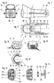
- the shower wall bar shown in FIGS. 1 to 3 is formed by a wall bar 6 and a slider which is rotatable and axially displaceably arranged on the wall bar 6 and which is provided with a decorative cover 5.
- the wall bar is arranged with brackets - not shown in the drawing - on a building wall at a distance approximately perpendicular.
- the wall bar 6 is designed as a tube with a circular cross section.
- the slider is formed by a support body 1, a clamping element 2, a spherical body 3, a locking element 4 and a decorative cover 5, consisting of a front sleeve 50 and a bracket piece 51.
- a continuous bore 10 is provided in the support body 1 at one end area, on the wall of which in one half two protrusions 11 running at a distance from one another parallel to the central axis 100 are formed in one piece with the support body 1, as shown in particular in FIGS. 3, 5 , 6 and 9 can be seen.
- the projections 11 are placed at an angle 110 of approximately 60 ° in one half of the bore 10 and protrude approximately 0.1 to 1.5 mm, preferably 0.5 mm, radially in the bore 10.
- the tensioning element 2 is provided opposite the two projections 11 in the other half of the bore 10.
- the clamping element 2 as can be seen in particular from FIGS. 13 and 14, is formed by an adjusting screw 23 which is held in the support body 1 by means of thread 230.
- a circular disk 20 with a guide pin 22 is received in a central bore 231 of the set screw 23.
- the guide pin 22 has snap tongues 220 on its front area so that the circular disk 20 is axially locked in the set position in the set screw 23.
- a rubber-elastic ring 24 is arranged as a spring on the guide pin 22.
- a hexagon socket 232 is formed in the area of the central bore 231 for the attachment of a turning tool.
- the circular disc 20 is provided with a protruding, arched end face 21, so that a precise contact with the wall bar 6 is ensured.
- the support body 1 is provided with a fork 12, between whose two arms 120 the spherical body 3 is arranged, as can be seen in particular from FIGS. 5 and 6 of the drawing.
- a tubular extension 13 is formed on the support body 1, in which the locking element 4 is arranged.
- a further inner axial guide 130 is formed coaxially in the extension 13, as can be seen in particular from FIG. 8 of the drawing, which ensures a non-rotatable axial guide of the latching element 4.
- the support body 1 in the region of the outside of the arms 120 each has a holding rail 14, as can be seen in particular from FIGS. 7, 8 and 9.
- a resilient snap tongue 140 is formed, with which the front sleeve 15 which can be pushed onto the holding rails 14 is locked in the inserted position.
- the support body 1 is advantageously made in one piece from a suitable plastic by injection molding.
- Ball body 3 has a tapered bore 30 an axial slot 31 for receiving one in the Drawing not shown hand shower with a corresponding Cone piece and hose line.
- the spherical body 3 is perpendicular to the axis of the taper bore with two diametrically opposed bearing journals 32, as is shown in particular in FIGS. 10, 11 and 12 can be seen.
- Bearing pin 32 has a radially projecting nose 320, with which in the installation position is prevented the arms 120 of the fork 12 can spread undesirably.
- the spherical body 3 are in the manner of a toothing rounded incisions 33 for attacking the locking element 4 trained.
- the locking element 4 consists of a plate-shaped collar 41, on the one hand a guide pin 42 with a polygonal profile for rotationally secure reception in the axial guide 130 and on the other hand a wedge piece 43 for engaging in the incisions 33 on the spherical body.
- a spring 40 is arranged between the inner axial guide 130 and the tubular extension 13, which is supported on the one hand in the base of the support body 1 and on the other hand on the collar 41 and thus the wedge piece 43 against the Shell surface of the spherical body 3 presses.
- the spherical body 3 with its bearing pins 32 is pressed radially out of the fork 12 of the supporting body 1, so that the protruding nose 320 in each case engages over an arm 120 on the outer surface.
- the protruding lugs 320 engage in a recess on the outer sides of the two arms 120.
- the lugs with the bearing pins can also be designed so that a special depression on the outside of the arms 120 is not necessary.
- the ball body 3 is thus only supported in the front half of the bearing bores 121 in the arms 120.
- the bearing pins 32 are reliably guided in the bearing bores 121 by the compressive force of the spring 40.
- a rotatable roller can also be arranged on the collar 41 with the aid of support bearings 440, as can be seen from FIGS. 18 to 20 of the drawing.
- the rotatably arranged roller enables extremely low-wear operation of the locking element in connection with the spherical body.
- the decorative cover 5 formed from the front sleeve 50 and the bracket piece 51 primarily serves for the shapely exterior design and the easy cleaning of the sliding piece.
- the front sleeve 50 is provided with two opposing openings 502, into which the snap tongues 140 partially enclose.
- Guide rails 501 are also integrally formed on the inner sides of the front sleeve 15 for guidance on the holding rails 14.
- latching lugs 510 are formed on the two side arms, which in the plug-in position encompass the rest of the openings 502, as can be seen in particular from FIG. 4.
- the front sleeve 50 also has recesses 500 which, on the one hand, allow the wall rod 6 to pass through and, on the other hand, allow the hand shower connected to a hose to be stored in the various pivoting positions of the spherical body 3.
- the bracket piece 51 also has the opening 511 on the rear, through which a rotary tool for adjusting the clamping element 2 can be inserted.
- the bracket piece 51 has a reinforcing rib 512 with plug stops 513.
- a slightly protruding bead 503 is also formed on both sides to enable a harmonious transition to the bracket piece 51.
- the slider described above can be assembled in the following way: First, the clamping element 2, which has been joined together to form a structural unit, is screwed into the provided threaded bore in the supporting body 1 with the thread 230, and then the locking element 4 with the spring 40 is pushed into the shoulder 13. Then the spherical body 3 is inserted laterally into the fork 12 with the bearing journal 32.
- the bearing pins 32 here have inclined surfaces 321, so that the fork 12 is elastically expanded in the region of the arms 120. On both sides of the arms 120, the stop ribs 122 come into the region of the pivot stop recess 34 of the spherical body 3.
- the arms 120 spring back into the original position, after the spherical body 3 has been released by the spring 40 the wedge piece 43 is pushed out of the fork 12 again by a short distance, so that the lugs 320 on the outside engage behind the arms 120 and rule out undesired spreading of the fork 12.
- the spherical body 3 can then be pivoted in the frame of the pivot stop recess 34 around the axis of the bearing journal 32 by an angle of approximately 40 °, the wedge piece 43 engaging in the notch 33 belonging to the selected pivot position and preventing unintentional pivoting. Then the front sleeve 50 can be pushed onto the support body 1 from the fork side.
- the guide rails 501 formed on the sides of the front sleeve 50 reach the holding rails 14 formed laterally on the supporting body 1.
- the snap tongues 140 are deflected in order to spring back into the openings 502 after reaching the plug position and to close the front sleeve 50 in the plug position lock. Then the bracket piece 51 can be pushed onto the support body 1 from behind.
- the two arms of the bracket piece 51 are first expanded slightly elastically because of the locking lugs 510, in order to then snap into a remaining area of the openings 502 of the front sleeve 50 in the plug-in position, the plug stops 513 of the reinforcing rib 512 on the front side at the same time in front of the openings 502 of the front sleeve 20 get to the plant.
- the openings 502 are completely covered to the outside by the bracket piece 51.
- the end regions of the bracket piece 51 lie on the end face against the bead 503 formed on the front sleeve 51 and thus close off the front sleeve 50 in the rear region.
- the slide is completely assembled and can be pushed axially onto a wall bar 6 as a structural unit.
- a turning tool can be introduced into the clamping element 2 through the opening 511.
- the contact pressure can then be precisely adjusted with a rotary movement of the tensioning element 2.
- the thread 230 is designed as a fine thread, so that a sensitive and precise setting and contact pressure is made possible. Then the slider is ready for use.
- the radial preload being set so that on the one hand the slide 1 can be easily moved by hand on the wall bar 6 and on the other hand in the desired positions on the wall bar 6 remains securely.
- the required stiffness of the slider subsides, the required stiffness can be easily restored by adjusting the tensioning element 2.
Landscapes
- Health & Medical Sciences (AREA)
- Life Sciences & Earth Sciences (AREA)
- Engineering & Computer Science (AREA)
- Hydrology & Water Resources (AREA)
- Public Health (AREA)
- Water Supply & Treatment (AREA)
- Domestic Plumbing Installations (AREA)
- Bathtubs, Showers, And Their Attachments (AREA)
- Nozzles (AREA)
- Coating With Molten Metal (AREA)
- Clamps And Clips (AREA)
- Medicines Containing Plant Substances (AREA)
- Pharmaceuticals Containing Other Organic And Inorganic Compounds (AREA)
- Curtains And Furnishings For Windows Or Doors (AREA)
Applications Claiming Priority (2)
| Application Number | Priority Date | Filing Date | Title |
|---|---|---|---|
| DE19705285A DE19705285A1 (de) | 1997-02-12 | 1997-02-12 | Gleitstück für Brausewandstange |
| DE19705285 | 1997-02-12 |
Publications (2)
| Publication Number | Publication Date |
|---|---|
| EP0859090A1 true EP0859090A1 (fr) | 1998-08-19 |
| EP0859090B1 EP0859090B1 (fr) | 2003-12-10 |
Family
ID=7819984
Family Applications (1)
| Application Number | Title | Priority Date | Filing Date |
|---|---|---|---|
| EP98101577A Expired - Lifetime EP0859090B1 (fr) | 1997-02-12 | 1998-01-30 | Dispositif coulissant pour colonne murale de douche |
Country Status (12)
| Country | Link |
|---|---|
| US (1) | US6024331A (fr) |
| EP (1) | EP0859090B1 (fr) |
| JP (1) | JPH10219771A (fr) |
| AT (1) | ATE256224T1 (fr) |
| CA (1) | CA2227996A1 (fr) |
| CZ (1) | CZ43298A3 (fr) |
| DE (2) | DE19705285A1 (fr) |
| DK (1) | DK0859090T3 (fr) |
| ES (2) | ES2212152T3 (fr) |
| HU (1) | HU220401B (fr) |
| PL (1) | PL324744A1 (fr) |
| RU (1) | RU2183419C2 (fr) |
Cited By (1)
| Publication number | Priority date | Publication date | Assignee | Title |
|---|---|---|---|---|
| EP4159938A4 (fr) * | 2020-05-28 | 2024-06-05 | Fujian Xihe Sanitary Ware Technology Co., Ltd. | Cadre mobile |
Families Citing this family (23)
| Publication number | Priority date | Publication date | Assignee | Title |
|---|---|---|---|---|
| DE19854791A1 (de) * | 1998-11-27 | 2000-05-31 | Grohe Kg Hans | Haltevorrichtung für eine Handbrause |
| EP1160384A1 (fr) * | 2000-05-31 | 2001-12-05 | Johs. Tandrup Metalvarefabrik APS | Support de pomme de douche pour la fixation d'une pomme de douche dans une position spécifique sur une barre de guidage murale |
| US20030150969A1 (en) * | 2002-01-24 | 2003-08-14 | Sam Zhadanov | Device for holding a hand-held showerhead and the like |
| USD489798S1 (en) | 2002-12-10 | 2004-05-11 | Moen Incorporated | Shower holder attachment |
| USD493864S1 (en) | 2002-12-13 | 2004-08-03 | Hansgrohe Ag | Holder for hand showers and shower hoses |
| DE10260204A1 (de) | 2002-12-13 | 2004-06-24 | Hansgrohe Ag | Schwenkarmanordnung für Sanitärgegenstände |
| USD552455S1 (en) * | 2006-02-28 | 2007-10-09 | Shower Solutions, Llc | Curved shower rod bracket |
| US7766291B2 (en) * | 2006-04-19 | 2010-08-03 | Kohler Co. | Handshower slide bar |
| USD590698S1 (en) * | 2006-08-23 | 2009-04-21 | Shower Solutions, Llc | Shower rod bracket |
| USD557590S1 (en) | 2006-08-23 | 2007-12-18 | Shower Solutions, Llc | Shower rod bracket |
| USD567637S1 (en) * | 2006-10-05 | 2008-04-29 | Shower Solutions, Llc | Shower rod bracket |
| TWM310910U (en) * | 2006-11-27 | 2007-05-01 | De-Sen Chen | Improved structure of position device of a shower nozzle |
| US7721363B2 (en) * | 2008-06-27 | 2010-05-25 | Sheng Tai Brassware Co., Ltd. | Slide rail |
| US8215501B2 (en) | 2009-08-05 | 2012-07-10 | Focus Products Group, Llc | Adjustable curtain rod |
| US8991625B2 (en) | 2012-05-02 | 2015-03-31 | Focus Products Group International, Llc | Adjustable curtain rod assembly |
| GB2555421B (en) * | 2016-10-26 | 2021-08-04 | Kohler Mira Ltd | Slide rail mechanism |
| CN108906444A (zh) * | 2017-04-01 | 2018-11-30 | 厦门松霖科技股份有限公司 | 一种出水终端的悬挂结构 |
| US11179734B2 (en) * | 2017-12-08 | 2021-11-23 | Delta Faucet Company | Combined multi-purpose handheld shower and showerhead |
| DE102018209985B4 (de) * | 2018-06-20 | 2025-08-14 | Hansgrohe Se | Stangenmontierbare Halterung |
| USD890884S1 (en) | 2018-12-28 | 2020-07-21 | Spectrum Brands, Inc. | Shower column |
| US11118332B2 (en) | 2019-08-30 | 2021-09-14 | Brasstech, Inc. | Handshower holder |
| US11634896B2 (en) * | 2020-09-03 | 2023-04-25 | Xiamen Galenpoo Kitchen & Bathroom Technology Co, Ltd. | Overhead shower connector structure |
| DE102020215084A1 (de) | 2020-11-30 | 2022-06-02 | Hansgrohe Se | Stangenmontierbare Haltevorrichtung und sanitäre Handbrausenhalteeinrichtung |
Citations (3)
| Publication number | Priority date | Publication date | Assignee | Title |
|---|---|---|---|---|
| DE9110622U1 (de) * | 1991-08-28 | 1991-10-02 | Eisen- Und Drahtwerk Erlau Ag, 7080 Aalen | Halter für einen Brausekopf |
| EP0526775A1 (fr) * | 1991-07-23 | 1993-02-10 | Friedrich Grohe Aktiengesellschaft | Support pour pomme de douche |
| EP0607877A1 (fr) * | 1993-01-21 | 1994-07-27 | Hans Grohe GmbH & Co. KG | Coulisseau pour barre murale |
Family Cites Families (13)
| Publication number | Priority date | Publication date | Assignee | Title |
|---|---|---|---|---|
| US1546739A (en) * | 1923-09-01 | 1925-07-21 | Lande Lester R Le | Vision protector |
| US2931613A (en) * | 1957-02-14 | 1960-04-05 | Grohe Hans | Clamp support for shower devices |
| US3167292A (en) * | 1963-12-12 | 1965-01-26 | Nathan L Meyerowitz | Bracket |
| DE7521122U (de) * | 1975-07-03 | 1976-02-26 | Hans Grohe Kg, 7622 Schiltach | Auf wandstange verschiebbarer handbrausehalter |
| SE394706B (sv) * | 1976-09-17 | 1977-07-04 | N Larsson | Duschhallare |
| DE3506120A1 (de) * | 1985-02-22 | 1986-08-28 | Hans Grohe Gmbh & Co Kg, 7622 Schiltach | Wandanschlussstueck fuer eine handbrause |
| US5070552A (en) * | 1989-02-03 | 1991-12-10 | Associated Mills, Inc. | Personalized hand held shower head |
| US4964573A (en) * | 1989-06-21 | 1990-10-23 | Pinchas Lipski | Showerhead adaptor means |
| DE4108773A1 (de) * | 1991-03-18 | 1992-09-24 | Grohe Kg Hans | Brausehalter fuer eine wandstange |
| KR970003925Y1 (ko) * | 1994-01-27 | 1997-04-24 | 아메리킨 스탠다아드 인코로레이팃드 | 샤워기 행거 |
| US5481765A (en) * | 1994-11-29 | 1996-01-09 | Wang; Wen-Mu | Adjustable shower head holder |
| DE19505719C2 (de) * | 1995-02-20 | 1997-03-13 | Wallisellen Ag Armaturen | Handbrausen-Gelenkhalter in Verbindung mit einer Gleitstange |
| US5632049A (en) * | 1996-01-25 | 1997-05-27 | Chen; Te-Sen | Holder assembly for a shower head |
-
1997
- 1997-02-12 DE DE19705285A patent/DE19705285A1/de not_active Withdrawn
- 1997-12-08 US US08/986,958 patent/US6024331A/en not_active Expired - Fee Related
-
1998
- 1998-01-26 CA CA002227996A patent/CA2227996A1/fr not_active Abandoned
- 1998-01-30 DK DK98101577T patent/DK0859090T3/da active
- 1998-01-30 ES ES98101577T patent/ES2212152T3/es not_active Expired - Lifetime
- 1998-01-30 HU HU9800168A patent/HU220401B/hu not_active IP Right Cessation
- 1998-01-30 DE DE59810371T patent/DE59810371D1/de not_active Expired - Fee Related
- 1998-01-30 AT AT98101577T patent/ATE256224T1/de not_active IP Right Cessation
- 1998-01-30 EP EP98101577A patent/EP0859090B1/fr not_active Expired - Lifetime
- 1998-02-05 JP JP10024767A patent/JPH10219771A/ja active Pending
- 1998-02-09 ES ES09800356U patent/ES1039601Y/es not_active Expired - Fee Related
- 1998-02-10 PL PL98324744A patent/PL324744A1/xx unknown
- 1998-02-11 RU RU98102536/12A patent/RU2183419C2/ru active
- 1998-02-12 CZ CZ98432A patent/CZ43298A3/cs unknown
Patent Citations (3)
| Publication number | Priority date | Publication date | Assignee | Title |
|---|---|---|---|---|
| EP0526775A1 (fr) * | 1991-07-23 | 1993-02-10 | Friedrich Grohe Aktiengesellschaft | Support pour pomme de douche |
| DE9110622U1 (de) * | 1991-08-28 | 1991-10-02 | Eisen- Und Drahtwerk Erlau Ag, 7080 Aalen | Halter für einen Brausekopf |
| EP0607877A1 (fr) * | 1993-01-21 | 1994-07-27 | Hans Grohe GmbH & Co. KG | Coulisseau pour barre murale |
Cited By (1)
| Publication number | Priority date | Publication date | Assignee | Title |
|---|---|---|---|---|
| EP4159938A4 (fr) * | 2020-05-28 | 2024-06-05 | Fujian Xihe Sanitary Ware Technology Co., Ltd. | Cadre mobile |
Also Published As
| Publication number | Publication date |
|---|---|
| CA2227996A1 (fr) | 1998-08-12 |
| ES2212152T3 (es) | 2004-07-16 |
| JPH10219771A (ja) | 1998-08-18 |
| HU220401B (hu) | 2002-01-28 |
| PL324744A1 (en) | 1998-08-17 |
| ATE256224T1 (de) | 2003-12-15 |
| ES1039601U (es) | 1999-01-01 |
| DK0859090T3 (da) | 2004-04-05 |
| CZ43298A3 (cs) | 1998-09-16 |
| ES1039601Y (es) | 1999-06-01 |
| DE59810371D1 (de) | 2004-01-22 |
| HU9800168D0 (en) | 1998-03-30 |
| EP0859090B1 (fr) | 2003-12-10 |
| US6024331A (en) | 2000-02-15 |
| DE19705285A1 (de) | 1998-08-13 |
| HUP9800168A1 (hu) | 1998-12-28 |
| RU2183419C2 (ru) | 2002-06-20 |
Similar Documents
| Publication | Publication Date | Title |
|---|---|---|
| EP0859090A1 (fr) | Dispositif coulissant pour colonne murale de douche | |
| EP0751261B1 (fr) | Support de pomme de douche | |
| DE10051805A1 (de) | WC-Sitzgelenk | |
| EP0768938A1 (fr) | Dispositif permettant la fixation amovible d'appareils de nettoyage | |
| WO2008009390A1 (fr) | Embout de sortie | |
| EP1386051A1 (fr) | Dispositif de guidage universel pour portes coulissantes d'un meuble | |
| DE102015101829A1 (de) | Spannklaue zur Anbringung an einer Gleitschiene eines Operationstisches | |
| EP0733839B1 (fr) | Mitigeur avec un levier | |
| DE2153875A1 (de) | Innenrueckblickspiegel fuer fahrzeuge | |
| EP2197692B1 (fr) | Compas comprenant une articulation avec un dispositif de blocage | |
| DE29719083U1 (de) | Ratschenschraubenschlüssel | |
| DE102015219175B4 (de) | Anschlussrohrstutzen für eine Sanitärarmatur | |
| DE4024614A1 (de) | Fenster- oder tuerbeschlag | |
| EP4012200B1 (fr) | Boulon d'encliquetage sollicité par ressort | |
| EP1870526A1 (fr) | Robinet sanitaire | |
| DE4123610A1 (de) | Einstellbares beduesungsventil | |
| DE19954922B4 (de) | Scharnier | |
| DE8809585U1 (de) | Beschlag für Fenster oder Türen | |
| EP1143078B1 (fr) | Robinet avec bec rotatif | |
| DE7713654U1 (de) | Scharnier fuer ein fenster, eine tuer o.dgl. | |
| DE19802917C2 (de) | Handbrause mit schwenkbarem Brausehalter | |
| EP0704580A2 (fr) | Garniture de douche avec élément de serrage ajustable | |
| EP1386048A1 (fr) | Suspension et fixation d'une tige | |
| DE4102133A1 (de) | Sanitaerarmatur mit schwenkauslauf | |
| DE29712060U1 (de) | Vorrichtung mit einem ortsfesten und einem verstellbaren Vorrichtungsteil |
Legal Events
| Date | Code | Title | Description |
|---|---|---|---|
| PUAI | Public reference made under article 153(3) epc to a published international application that has entered the european phase |
Free format text: ORIGINAL CODE: 0009012 |
|
| AK | Designated contracting states |
Kind code of ref document: A1 Designated state(s): AT BE CH DE DK ES FI FR GB IT LI NL SE |
|
| AX | Request for extension of the european patent |
Free format text: AL;LT;LV;MK;RO;SI |
|
| 17P | Request for examination filed |
Effective date: 19981219 |
|
| AKX | Designation fees paid |
Free format text: AT BE CH DE DK ES FI FR GB IT LI NL SE |
|
| RBV | Designated contracting states (corrected) |
Designated state(s): AT BE CH DE DK ES FI FR GB IT LI NL SE |
|
| RAP1 | Party data changed (applicant data changed or rights of an application transferred) |
Owner name: FRIEDRICH GROHE AG & CO. KG |
|
| 17Q | First examination report despatched |
Effective date: 20020812 |
|
| GRAH | Despatch of communication of intention to grant a patent |
Free format text: ORIGINAL CODE: EPIDOS IGRA |
|
| GRAS | Grant fee paid |
Free format text: ORIGINAL CODE: EPIDOSNIGR3 |
|
| GRAA | (expected) grant |
Free format text: ORIGINAL CODE: 0009210 |
|
| RAP1 | Party data changed (applicant data changed or rights of an application transferred) |
Owner name: GROHE WATER TECHNOLOGY AG & CO. KG |
|
| AK | Designated contracting states |
Kind code of ref document: B1 Designated state(s): AT BE CH DE DK ES FI FR GB IT LI NL SE |
|
| PG25 | Lapsed in a contracting state [announced via postgrant information from national office to epo] |
Ref country code: FI Free format text: LAPSE BECAUSE OF FAILURE TO SUBMIT A TRANSLATION OF THE DESCRIPTION OR TO PAY THE FEE WITHIN THE PRESCRIBED TIME-LIMIT Effective date: 20031210 |
|
| REG | Reference to a national code |
Ref country code: GB Ref legal event code: FG4D Free format text: NOT ENGLISH |
|
| REG | Reference to a national code |
Ref country code: CH Ref legal event code: EP |
|
| PGFP | Annual fee paid to national office [announced via postgrant information from national office to epo] |
Ref country code: BE Payment date: 20040105 Year of fee payment: 7 |
|
| PGFP | Annual fee paid to national office [announced via postgrant information from national office to epo] |
Ref country code: DK Payment date: 20040115 Year of fee payment: 7 |
|
| REF | Corresponds to: |
Ref document number: 59810371 Country of ref document: DE Date of ref document: 20040122 Kind code of ref document: P |
|
| PGFP | Annual fee paid to national office [announced via postgrant information from national office to epo] |
Ref country code: AT Payment date: 20040127 Year of fee payment: 7 |
|
| PGFP | Annual fee paid to national office [announced via postgrant information from national office to epo] |
Ref country code: GB Payment date: 20040128 Year of fee payment: 7 |
|
| PG25 | Lapsed in a contracting state [announced via postgrant information from national office to epo] |
Ref country code: LI Free format text: LAPSE BECAUSE OF NON-PAYMENT OF DUE FEES Effective date: 20040131 Ref country code: CH Free format text: LAPSE BECAUSE OF NON-PAYMENT OF DUE FEES Effective date: 20040131 |
|
| PG25 | Lapsed in a contracting state [announced via postgrant information from national office to epo] |
Ref country code: SE Free format text: LAPSE BECAUSE OF FAILURE TO SUBMIT A TRANSLATION OF THE DESCRIPTION OR TO PAY THE FEE WITHIN THE PRESCRIBED TIME-LIMIT Effective date: 20040310 |
|
| REG | Reference to a national code |
Ref country code: DK Ref legal event code: T3 |
|
| GBT | Gb: translation of ep patent filed (gb section 77(6)(a)/1977) |
Effective date: 20040324 |
|
| ET | Fr: translation filed | ||
| REG | Reference to a national code |
Ref country code: ES Ref legal event code: FG2A Ref document number: 2212152 Country of ref document: ES Kind code of ref document: T3 |
|
| REG | Reference to a national code |
Ref country code: CH Ref legal event code: PL |
|
| PLBE | No opposition filed within time limit |
Free format text: ORIGINAL CODE: 0009261 |
|
| STAA | Information on the status of an ep patent application or granted ep patent |
Free format text: STATUS: NO OPPOSITION FILED WITHIN TIME LIMIT |
|
| 26N | No opposition filed |
Effective date: 20040913 |
|
| PG25 | Lapsed in a contracting state [announced via postgrant information from national office to epo] |
Ref country code: GB Free format text: LAPSE BECAUSE OF NON-PAYMENT OF DUE FEES Effective date: 20050130 Ref country code: AT Free format text: LAPSE BECAUSE OF NON-PAYMENT OF DUE FEES Effective date: 20050130 |
|
| PG25 | Lapsed in a contracting state [announced via postgrant information from national office to epo] |
Ref country code: DK Free format text: LAPSE BECAUSE OF NON-PAYMENT OF DUE FEES Effective date: 20050131 Ref country code: BE Free format text: LAPSE BECAUSE OF NON-PAYMENT OF DUE FEES Effective date: 20050131 |
|
| PGFP | Annual fee paid to national office [announced via postgrant information from national office to epo] |
Ref country code: ES Payment date: 20050215 Year of fee payment: 8 |
|
| BERE | Be: lapsed |
Owner name: *GROHE WATER TECHNOLOGY A.G. & CO. K.G. Effective date: 20050131 |
|
| REG | Reference to a national code |
Ref country code: DK Ref legal event code: EBP |
|
| GBPC | Gb: european patent ceased through non-payment of renewal fee |
Effective date: 20050130 |
|
| PGFP | Annual fee paid to national office [announced via postgrant information from national office to epo] |
Ref country code: NL Payment date: 20060131 Year of fee payment: 9 |
|
| NLV4 | Nl: lapsed or anulled due to non-payment of the annual fee |
Effective date: 20070801 |
|
| BERE | Be: lapsed |
Owner name: *GROHE WATER TECHNOLOGY A.G. & CO. K.G. Effective date: 20050131 |
|
| PGFP | Annual fee paid to national office [announced via postgrant information from national office to epo] |
Ref country code: IT Payment date: 20070618 Year of fee payment: 10 |
|
| PG25 | Lapsed in a contracting state [announced via postgrant information from national office to epo] |
Ref country code: NL Free format text: LAPSE BECAUSE OF NON-PAYMENT OF DUE FEES Effective date: 20070801 |
|
| REG | Reference to a national code |
Ref country code: ES Ref legal event code: FD2A Effective date: 20070131 |
|
| PGFP | Annual fee paid to national office [announced via postgrant information from national office to epo] |
Ref country code: FR Payment date: 20070111 Year of fee payment: 10 |
|
| PG25 | Lapsed in a contracting state [announced via postgrant information from national office to epo] |
Ref country code: ES Free format text: LAPSE BECAUSE OF NON-PAYMENT OF DUE FEES Effective date: 20070131 |
|
| REG | Reference to a national code |
Ref country code: FR Ref legal event code: ST Effective date: 20081029 |
|
| PG25 | Lapsed in a contracting state [announced via postgrant information from national office to epo] |
Ref country code: FR Free format text: LAPSE BECAUSE OF NON-PAYMENT OF DUE FEES Effective date: 20080131 |
|
| PGFP | Annual fee paid to national office [announced via postgrant information from national office to epo] |
Ref country code: DE Payment date: 20090122 Year of fee payment: 12 |
|
| PG25 | Lapsed in a contracting state [announced via postgrant information from national office to epo] |
Ref country code: IT Free format text: LAPSE BECAUSE OF NON-PAYMENT OF DUE FEES Effective date: 20080130 |
|
| PG25 | Lapsed in a contracting state [announced via postgrant information from national office to epo] |
Ref country code: DE Free format text: LAPSE BECAUSE OF NON-PAYMENT OF DUE FEES Effective date: 20100803 |