EP2197692B1 - Compas comprenant une articulation avec un dispositif de blocage - Google Patents
Compas comprenant une articulation avec un dispositif de blocage Download PDFInfo
- Publication number
- EP2197692B1 EP2197692B1 EP08840473.6A EP08840473A EP2197692B1 EP 2197692 B1 EP2197692 B1 EP 2197692B1 EP 08840473 A EP08840473 A EP 08840473A EP 2197692 B1 EP2197692 B1 EP 2197692B1
- Authority
- EP
- European Patent Office
- Prior art keywords
- compass
- joint element
- compasses according
- joint
- projection
- Prior art date
- Legal status (The legal status is an assumption and is not a legal conclusion. Google has not performed a legal analysis and makes no representation as to the accuracy of the status listed.)
- Not-in-force
Links
Images





Classifications
-
- B—PERFORMING OPERATIONS; TRANSPORTING
- B43—WRITING OR DRAWING IMPLEMENTS; BUREAU ACCESSORIES
- B43L—ARTICLES FOR WRITING OR DRAWING UPON; WRITING OR DRAWING AIDS; ACCESSORIES FOR WRITING OR DRAWING
- B43L9/00—Circular curve-drawing or like instruments
- B43L9/02—Compasses
-
- B—PERFORMING OPERATIONS; TRANSPORTING
- B43—WRITING OR DRAWING IMPLEMENTS; BUREAU ACCESSORIES
- B43L—ARTICLES FOR WRITING OR DRAWING UPON; WRITING OR DRAWING AIDS; ACCESSORIES FOR WRITING OR DRAWING
- B43L9/00—Circular curve-drawing or like instruments
- B43L9/16—Features common to compasses, dividers, and callipers
- B43L9/20—Pivots
Definitions
- the invention relates to a compass with a first compass section and a second compass section according to the preamble of claim 1.
- the invention is therefore based on the object to provide a compass with an improved locking device, in which an unintentional adjustment of the joint is prevented.
- the invention provides that, according to claim 1 which is spaced from the axis of rotation of the joint piece and the clamping force acts perpendicular to the axis of rotation of the joint piece.
- the invention is based on the finding that a significantly improved clamping effect can be achieved in comparison with the prior art if the surfaces generating the static friction are not located in or directly on the axis of rotation. When located away from the pivot axis of rotation, these surfaces can accommodate significantly greater torques compared to conventional locking devices to prevent inadvertent release and adjustment of the hinge.
- the first compass portion and the second compass portion may be formed on an accessory of the compass, in particular on an extension rod.
- the first compass section and the second circular section may be designed as compass leg sections which form a compass leg which is connected to a second compass leg via a compass head.
- the joint piece has the basic shape of a half-disk and that the contour of the end portion of the first or second compass leg portion cooperating with the joint piece is formed substantially opposite thereto.
- the curved side surface of the half-disk performs a rotational movement relative to the opposite surface of the compass leg portion and can be fixed in any relative position by means of the locking device.
- the opposite surfaces are pressed against each other, whereby the position of the joint is fixed.
- the joint piece on opposite sides Has pin portions which engage in corresponding recesses of the circular leg portion.
- the imaginary connecting line of the two pin sections forms the axis of rotation of the joint piece.
- the pin sections could also be arranged on the circular leg section, which engage in corresponding recesses of the joint piece. It is also conceivable to use a separate shaft, which allows a rotational movement of the joint piece.
- the end section of the first or second compass leg section is designed to be approximately U-shaped for receiving the hinge section.
- the hinge piece between the two U-shaped legs may be included so that it is partially hidden.
- the joint piece has a bore or recess for the threaded element formed as a spindle.
- the spindle may extend through the hinge piece and be locked on one side, preferably on the outside of the compass, by means of a nut.
- the joint piece is releasably connectable or connected to the arranged away from the compass head circular leg section.
- the circular leg section arranged away from the compass head can be designed as a circular insert. In this way, conventional compass inserts can be connected via the joint piece with the compass.
- Trained as a spindle threaded element of the compass according to the invention has a spindle head which is rotatably mounted relative to the joint piece. As a result, an undesired rotation of the spindle during actuation of the locking device is prevented.
- the compass in a particularly advantageous embodiment of the compass according to the invention, it may be provided that in the interior of the joint piece an opening having a clamping block is arranged, through which the spindle is guided and to which the head of the spindle rests. Since the clamping block is movable and the joint piece has an opening for a compass insert, compass inserts with different journal diameters can be clamped. The clamping automatically takes effect when the joint is locked.
- the clamping block and the joint piece for compass inserts with a pin diameter of 3.5 mm and 4 mm are suitable.
- the hinge piece on the curved side of the half-disc may have a projection which limits the rotational movement of the joint and prevents further rotation of the outer circular leg portion to the outside.
- the projection may be movable along a U-shaped end portion of the compass leg portion.
- the projection may be cylindrical, particularly preferred is a variant in which the projection has a bore or recess for the spindle. In this variant, the spindle nut is in the locked state on the end face of the projection.
- the joint piece has a projection pointing towards the compass head, which is movable along a groove of the compass leg section and limits the rotational movement of the joint when abutting against the end of the groove.
- This second projection which is arranged on the joint piece as an alternative or in addition to the mentioned first projection, limits the rotational movement of the circular leg portion when a predetermined angle is reached.
- the compass according to the invention can also have a known adjusting spindle.
- a variant of the compass according to the invention provides that the joint piece forms an integral component with the threaded element.
- the joint piece and the threaded element are integrally formed by the threaded element is injection-molded, for example, by injection molding on the joint piece.
- the compass consisting of the threaded element and the joint piece integral component may have at least one projection or a recess, the one or with a corresponding counter-trained depression or a correspondingly opposite projection on a compass portion, in particular on a compass leg, generating a form fit interacts.
- the compass can be securely fixed in a desired relative position of the two compass sections.
- a plurality of juxtaposed projections or depressions may be arranged on the compass section.
- the at least one projection or the at least one depression is arranged in the region of the transition between the threaded element and the joint piece.
- Compass 1 shown in a perspective view comprises compass legs 2, 3, which are connected to one another via a compass head 4.
- Each circular leg 2, 3 consists of a first circular leg section 5, 6 and a second circular leg section 7, 8, wherein a first circular leg section 5, 6 and a second circular leg section 7, 8 are connected to each other via a hinge 9, 10.
- the joints 9, 10 each have a locking device, with which the second circular leg sections 7, 8 can be fixed in a certain position to set a desired radius of the compass.
- the second circular leg portions 7, 8 are formed as compass inserts, while the circular leg portion 7 at its end a needle, the circular leg portion 8 has at its end a pencil lead.
- the joints 9, 10 of the circle 1 each have a joint piece 13, which in the Fig. 2A to 2D is shown in various perspective views.
- the hinge piece 13 has substantially the shape of a half-disc and has a bent peripheral surface 14 extending over approximately 180 ° and semicircular side surfaces 15, 16.
- the joint piece 13 When installed, the joint piece 13 is in the region of the end portion of the circular leg portion 5, which in the Figs. 3A to 3C is shown in perspective views.
- the joint piece On both semicircular surfaces 15, 16, the joint piece has cylindrical projections formed as pin sections 17, 18 which, when installed, are inserted into recesses 19, 20 of the limbs of the U-shaped end section 21 of the circular leg section 5.
- An imaginary line connecting the pin sections 17, 18 forms the axis of rotation of the joint piece 13.
- the joint piece 13 Approximately in the middle of the peripheral surface 14, the joint piece 13 has a cylindrical projection 22 with a bore through which a spindle can be inserted.
- the joint piece 13 has at one end of the peripheral surface 14 a further projection 23, which has a rectangular cross-section in the illustrated embodiment.
- This projection 23 is movable along a groove 24 in the center of the U-shaped end portion 21 of the circular leg portion 5.
- the groove 24 is bent according to the semicircular shape of the joint piece 13.
- At the end of the groove 24 of the projection 23 of the joint piece 13 runs against a stop, not shown, the the rotational movement of the joint piece 13 and thus limits the opening angle of the circle 1.
- the joint piece 13 on its flat side an opening 25, in which the in the FIGS. 4A and 4B shown clamping block 26 can be used.
- the clamping block 26 has a cuboidal basic shape, one side is concave and thus to the outer contour of the in Fig. 5 shown pin 27 of a compass insert 28 adapted.
- the clamping block 26 has an opening 29 through which a spindle can be inserted.
- Fig. 6A shows a side view of a compass leg
- Fig. 6B shows an enlarged view of a section along the line VI-VI.
- the knurled nut 11 is screwed onto the spindle 30, whose spindle head 31 is shaped so that it is non-rotatably inserted into the opening of the clamping block 26.
- the clamping block 26 abuts both the spindle head 31 and the U-shaped pin 27 of the compass insert 28 and clamps the compass insert 28 against the hinge piece 13, which in turn is pressed against the circular leg portion 5.
- the clamping force is generated by tightening the knurled nut 11.
- the laterally projecting from the joint piece 13 pin portions 17, 18, which form the axis of rotation of the joint piece 13, are supported in the recesses 19, 20 of the end portion 21 of the circular leg portion 5.
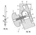
- Fig. 7A shows a side view of the circle 1
- Fig. 7B shows the area of the joint in an enlarged view cut along the line VII-VII.
- the joint 9 is shown in a bent position.
- the clamping effect is achieved by tightening the knurled nut 11, which is bolted to the spindle 30 and the spindle head 31 presses the clamping block 26 against the lower or outer circular leg portion 7.
- the hinge piece 13 rests with a part of its peripheral surface 14 on the corresponding counter surface of the first or upper circular leg portion 5. Likewise, it is due to mating surfaces of the second, lower circular leg portion 7, so that the circular leg sections 5, 7 set by the joint piece 13 in the Position held and clamped.
- Fig. 7B is also the arranged on the hinge piece 13 projection 23 is shown, which abuts at a certain opening angle against a stop surface in the groove 24, whereby the opening angle is limited.
- Fig. 8 shows an embodiment in which the joint is formed on an extension rod.
- extension rod 32 has at its upper end a U-shaped pin 27 which can be inserted and locked in a corresponding opening of a circular portion.
- a hinge piece 13 At the opposite end of the extension rod 32 is a hinge piece 13 with a clamping block 26 and a nut 11, wherein the hinge piece 13 and the components cooperating therewith identical to those in the FIGS. 2 to 4 shown compass components are constructed.
- the hinge piece 13 has at its free end an opening into which a compass insert can be inserted.
- FIGs. 9A, 9B, 10A and 10B an embodiment is shown in which the hinge piece forms an integral component with the threaded element.
- the semi-disc-shaped joint piece 33 has a molded thread element 34 which replaces the spindle provided in the previous embodiments.
- a nut 11 can be screwed onto the threaded element in order to clamp circular leg sections 35, 36 together.
- the hinge piece 33 has a cavity 37 into which the compass leg 36 can be inserted.
- the nut 11 generates a clamping force which acts perpendicular to the axis of rotation of the hinge piece 33.
- the hinge piece 33 is clamped in the clamped state on its inner side in the region of the cavity 37 against the circular portion 36 and on its outer side against the circular portion 35.
- FIGS. 9 and 10 another embodiment of a compass is shown, which is similar to that in the FIGS. 9 and 10 embodiment shown is constructed.
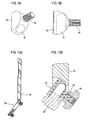
- Fig. 11A shows a perspective view of a hinge piece 38 having a threaded member 34.
- two projections 39th Fig. 11B shows the joint piece 38 in a side view
- Fig. 11C shows the projection 39 in an enlarged view
- Fig. 11D shows the hinge piece 38 in a side view.
- Fig. 13A shows a front view
- Fig. 13B a along the line XIII-XIII sectional view of a circular portion 40
- Fig. 13C shows the end portion 41 of the circular portion 40 in an enlarged view.
- the latter has a plurality of recesses 42 arranged next to one another, the contour of which is in each case formed opposite to the contour of a projection 39.
- the joint can withstand higher forces and torques than previously used joints, so that unintentional adjustment is prevented.
Landscapes
- Pivots And Pivotal Connections (AREA)
- Clamps And Clips (AREA)
Claims (21)
- Compas (1) comprenant une première section de compas (5, 6) et une deuxième section de compas (7, 8) qui sont reliées l'une avec l'autre par le biais d'une articulation (9, 10) présentant un dispositif de blocage, qui comprend une pièce d'articulation (13, 33, 38) montée de façon à pouvoir tourner autour d'un axe de rotation par rapport à la première ou à la deuxième section de compas (5, 6, 7, 8), dans lequel le dispositif de blocage présente un élément fileté (34) produisant une force de serrage coopérant avec un écrou (11, 12) destiné à serrer la pièce d'articulation (13, 33, 38) dans la position bloquée par rapport à la première et à la deuxième section de compas, caractérisé en ce que le dispositif de blocage est situé à distance de l'axe de rotation de la pièce d'articulation (13, 33, 38) et en ce que la force de serrage s'exerce perpendiculairement à l'axe de rotation de la pièce d'articulation (13, 33, 38).
- Compas selon la revendication 1, caractérisé en ce que la première section de compas et la deuxième section de compas sont réalisées sur une pièce d'accessoire du compas, en particulier sur une tige de prolongement.
- Compas selon la revendication 1, caractérisé en ce que la première section de compas et la deuxième section de compas sont réalisées comme sections de bras de compas (5, 7), qui forment un bras de compas (2) qui est relié avec un deuxième bras de compas (3) par le biais d'une tête de compas (4).
- Compas selon la revendication 3, caractérisé en ce que la pièce d'articulation (13) présente la forme de base d'un demi-cercle et le contour de la section d'extrémité (21), coopérant avec la pièce d'articulation (13), de la première ou de la deuxième section de bras de compas (5) est réalisé de façon sensiblement opposée à celle-ci.
- Compas selon la revendication 3 ou 4, caractérisé en ce que la pièce d'articulation (13) présente, sur des côtés situés en opposition, des sections de tenons (17, 18) qui s'engagent dans des évidements correspondants (19, 20) de la section de bras de compas (5).
- Compas selon l'une des revendications 3 à 5, caractérisé en ce que la section d'extrémité (21) de la première ou de la deuxième section de bras de compas (5) est réalisée approximativement en forme de U de façon à recevoir la pièce d'articulation (13).
- Compas selon l'une des revendications 3 à 6, caractérisé en ce que la pièce d'articulation (13) présente un forage ou un évidement pour l'élément fileté réalisé comme broche (30).
- Compas selon l'une des revendications 3 à 7, caractérisé en ce que la pièce d'articulation (13) peut être reliée ou est reliée de façon détachable avec la section de bras de compas (7, 8) agencée à distance de la tête de compas (4).
- Compas selon la revendication 8, caractérisé en ce que la section de bras de compas (7, 8) agencée à distance de la tête de compas (4) est réalisée comme empiècement du compas (28).
- Compas selon l'une des revendications 7 à 9, caractérisé en ce que la broche (30) est montée au moyen de sa tête de broche (31) de façon à ne pas pouvoir tourner par rapport à la pièce d'articulation (13).
- Compas selon la revendication 10, caractérisé en ce qu'il est agencé, à l'intérieur de la pièce d'articulation (13), un bloc de serrage mobile (26) présentant une ouverture (29), à travers lequel la broche (30) est guidée et sur lequel la tête de la broche (31) prend appui.
- Compas selon la revendication 11, caractérisé en ce que la pièce d'articulation (13) présente une ouverture (25) pour un empiècement du compas (28).
- Compas selon l'une des revendications 4 à 12, caractérisé en ce que la pièce d'articulation (13) présente, sur son côté courbé, une saillie (22) qui limite le mouvement de rotation de l'articulation (9, 10).
- Compas selon la revendication 13, caractérisé en ce que la saillie (22) peut être déplacée le long d'un évidement de la section d'extrémité en forme de U (21) de la section de bras de compas (5).
- Compas selon la revendication 13 ou 14, caractérisé en ce que la saillie (22) est réalisée en forme de cylindre.
- Compas selon l'une des revendications 13 à 15, caractérisé en ce que la saillie (22) présente un forage ou un évidement pour l'élément fileté réalisé de préférence comme broche (30).
- Compas selon l'une des revendications 3 à 16, caractérisé en ce que la pièce d'articulation (13) présente une saillie (23) dirigée vers la tête du compas, qui peut être déplacée le long d'une rainure (24) de la section de bras de compas (5) et qui, lorsqu'elle se situe à l'extrémité de la rainure (24), limite le mouvement de rotation de l'articulation (9).
- Compas selon l'une des revendications précédentes, caractérisé en ce qu'il présente une broche de réglage.
- Compas selon l'une des revendications précédentes, caractérisé en ce que la pièce d'articulation (33, 38) forme un composant d'une seule pièce avec l'élément fileté (34).
- Compas selon la revendication 19, caractérisé en ce que le composant d'une seule pièce constitué de l'élément fileté (34) et de la pièce d'articulation (38) présente au moins une saillie (39) ou un enfoncement qui coopère avec un enfoncement (42) réalisé de façon opposée correspondante ou avec une saillie réalisée de façon opposée correspondante au niveau d'une section du compas (40), en particulier d'un bras du compas, de façon à produire une liaison mécanique.
- Compas selon la revendication 20, caractérisé en ce que l'au moins une saillie (39) ou l'au moins un enfoncement est agencée ou agencé dans la zone de la transition entre l'élément fileté (34) et la pièce d'articulation (38).
Applications Claiming Priority (2)
| Application Number | Priority Date | Filing Date | Title |
|---|---|---|---|
| DE102007049513A DE102007049513B4 (de) | 2007-10-15 | 2007-10-15 | Zirkel |
| PCT/DE2008/001641 WO2009049590A2 (fr) | 2007-10-15 | 2008-10-10 | Compas |
Publications (2)
| Publication Number | Publication Date |
|---|---|
| EP2197692A2 EP2197692A2 (fr) | 2010-06-23 |
| EP2197692B1 true EP2197692B1 (fr) | 2013-05-08 |
Family
ID=40458729
Family Applications (1)
| Application Number | Title | Priority Date | Filing Date |
|---|---|---|---|
| EP08840473.6A Not-in-force EP2197692B1 (fr) | 2007-10-15 | 2008-10-10 | Compas comprenant une articulation avec un dispositif de blocage |
Country Status (5)
| Country | Link |
|---|---|
| US (1) | US8132333B2 (fr) |
| EP (1) | EP2197692B1 (fr) |
| CN (1) | CN101821114B (fr) |
| DE (1) | DE102007049513B4 (fr) |
| WO (1) | WO2009049590A2 (fr) |
Families Citing this family (7)
| Publication number | Priority date | Publication date | Assignee | Title |
|---|---|---|---|---|
| DE102007049513B4 (de) * | 2007-10-15 | 2009-07-30 | Draw.Tec Gmbh & Co. Kg | Zirkel |
| DE202010000074U1 (de) | 2010-01-22 | 2010-05-20 | Boden Reisszeuge Bavaria Gmbh | Zirkel sowie gelenkige Verbindung insbesondere zur Verwendung in einem Zirkel |
| USD823389S1 (en) * | 2016-10-27 | 2018-07-17 | Beifa Group Co., Ltd. | Compass |
| CN109774356A (zh) * | 2019-02-16 | 2019-05-21 | 安徽工程大学 | 一种教学圆规 |
| USD1073497S1 (en) * | 2023-07-28 | 2025-05-06 | Glendo Llc | Tapered point ends for a precision divider |
| USD1073494S1 (en) * | 2023-07-28 | 2025-05-06 | Glendo Llc | Mating protrusion and pocket for a precision divider |
| USD1073498S1 (en) * | 2023-07-28 | 2025-05-06 | Glendo Llc | Precision divider |
Family Cites Families (22)
| Publication number | Priority date | Publication date | Assignee | Title |
|---|---|---|---|---|
| US479112A (en) | 1892-07-19 | Dividers | ||
| DE331973C (de) * | 1921-01-17 | Spezial Werkzeugfabrik Calw G | Feststellvorrichtung fuer das Zirkelgelenk | |
| US225436A (en) | 1880-03-09 | Dividers | ||
| US1284372A (en) * | 1915-11-19 | 1918-11-12 | Emil Lawrenz | Scribing instrument. |
| US1466712A (en) * | 1921-05-23 | 1923-09-04 | Pease C F Co | Drawing instrument |
| US2297999A (en) * | 1940-11-28 | 1942-10-06 | Francis E Vaughan | Compass |
| US2333307A (en) * | 1942-01-30 | 1943-11-02 | Edward Z Galea | Measuring and drafting instrument |
| DE911546C (de) | 1951-03-14 | 1954-11-02 | Weber Georg | Zirkel mit mindestens einem gelenkig geteilten Schenkel |
| US3335497A (en) * | 1966-03-07 | 1967-08-15 | Keuffel & Esser Co | Scribing instruments |
| US3358371A (en) * | 1966-12-07 | 1967-12-19 | Sr Fred H Liesong | Scribing compass or divider |
| FR1592505A (fr) | 1968-05-03 | 1970-05-19 | ||
| US3768166A (en) * | 1972-05-08 | 1973-10-30 | P Elliott | Drawing instruments |
| FR2573356B1 (fr) | 1984-11-22 | 1988-08-19 | Manuf Articles Precision | Dispositif pour le montage articule d'instruments tracants et de pointes sur les branches d'un compas, et compas de dessin comportant application de ce dispositif |
| DE8620276U1 (de) * | 1986-07-29 | 1987-11-26 | Kiefer, Klaus Jürgen, 2000 Hamburg | Messzirkel. |
| DE4119136A1 (de) * | 1991-06-11 | 1992-12-17 | Intertech Zeichengeraete Gmbh | Gelenkverbindung fuer zweiteilige zirkelschenkel |
| CA2144089A1 (fr) * | 1992-09-08 | 1994-03-17 | Etienne Nicholas De Souza | Compas a pivot de securite |
| RO109305B1 (ro) * | 1993-10-14 | 1995-01-30 | Ioan Condur | Compas pivotant |
| DE19635599A1 (de) * | 1996-09-02 | 1998-03-05 | Staedtler Fa J S | Zirkel mit Einstellmitteln |
| DE102005038800B3 (de) | 2005-08-17 | 2006-12-07 | Ralph-Dieter Schmidt | Zirkel mit Feineinstellung zum Anreißen und Zeichnen von Kreisen |
| US7937843B2 (en) * | 2007-04-12 | 2011-05-10 | Intertech Zeichengeraete Gmbh | Compass having a leg joint and information bearing surfaces |
| DE102007017558A1 (de) * | 2007-04-12 | 2008-10-16 | Intertech Zeichengeräte GmbH | Zirkel mit Schenkelgelenk und Informationsträgerflächen |
| DE102007049513B4 (de) * | 2007-10-15 | 2009-07-30 | Draw.Tec Gmbh & Co. Kg | Zirkel |
-
2007
- 2007-10-15 DE DE102007049513A patent/DE102007049513B4/de not_active Expired - Fee Related
-
2008
- 2008-10-10 US US12/679,270 patent/US8132333B2/en active Active
- 2008-10-10 CN CN200880111515.1A patent/CN101821114B/zh not_active Expired - Fee Related
- 2008-10-10 EP EP08840473.6A patent/EP2197692B1/fr not_active Not-in-force
- 2008-10-10 WO PCT/DE2008/001641 patent/WO2009049590A2/fr not_active Ceased
Also Published As
| Publication number | Publication date |
|---|---|
| WO2009049590A3 (fr) | 2009-08-20 |
| US8132333B2 (en) | 2012-03-13 |
| DE102007049513A1 (de) | 2009-04-23 |
| EP2197692A2 (fr) | 2010-06-23 |
| WO2009049590A2 (fr) | 2009-04-23 |
| CN101821114B (zh) | 2013-04-24 |
| US20100307014A1 (en) | 2010-12-09 |
| DE102007049513B4 (de) | 2009-07-30 |
| CN101821114A (zh) | 2010-09-01 |
Similar Documents
| Publication | Publication Date | Title |
|---|---|---|
| EP2197692B1 (fr) | Compas comprenant une articulation avec un dispositif de blocage | |
| EP1785125B1 (fr) | Charnière pour connecter deux éléments d'une surface de support d'un patient | |
| EP3658336B1 (fr) | Dispositif de retenu à crochets pour une machine-outil | |
| EP2685204B1 (fr) | Dispositif de montage d'un dispositif de visée sur une arme à feu de poing | |
| EP2812622B1 (fr) | Tête de support | |
| EP0859090A1 (fr) | Dispositif coulissant pour colonne murale de douche | |
| EP3741944B1 (fr) | Paumelle | |
| DE10162861B4 (de) | Hebelzwinge | |
| DE2239853B2 (de) | Haltevorrichtung fuer aussenrueckblickspiegel von kraftfahrzeugen o.dgl. | |
| EP2283972B1 (fr) | Elément de fixation | |
| DE102007027046B4 (de) | Werkzeug zum Aufbringen eines Drehmoments | |
| EP1742008A1 (fr) | Dispositif pour monter une pièce sur resp. à un corps | |
| EP3009738B1 (fr) | Support de serrage | |
| DE102008061854B4 (de) | Scharnier | |
| EP1222406A1 (fr) | Element de retenue pour vis a tete | |
| EP1297265A1 (fr) | Dispositif pour fixer un premier element en position d'espacement par rapport a un deuxieme element | |
| DE202008009394U1 (de) | Vorrichtung zum lösbaren Verschließen des Endes eines Rohres | |
| DE102013111211B4 (de) | Zange | |
| EP3036065B1 (fr) | Serre-joint à serrage à vis | |
| CH690451A5 (de) | Scharnier. | |
| EP1024303B1 (fr) | Elément de fixation pour tige filetée | |
| EP0298270A2 (fr) | Outil tel qu'un outil de jardinage, d'agriculture, de nettoyage ou similaire | |
| DE29500046U1 (de) | Klemmvorrichtung, insbesondere an Operationstischen | |
| DE29909191U1 (de) | Exzenterspannzwinge | |
| DE102004054027B4 (de) | Gelenkband |
Legal Events
| Date | Code | Title | Description |
|---|---|---|---|
| PUAI | Public reference made under article 153(3) epc to a published international application that has entered the european phase |
Free format text: ORIGINAL CODE: 0009012 |
|
| 17P | Request for examination filed |
Effective date: 20091223 |
|
| AK | Designated contracting states |
Kind code of ref document: A2 Designated state(s): AT BE BG CH CY CZ DE DK EE ES FI FR GB GR HR HU IE IS IT LI LT LU LV MC MT NL NO PL PT RO SE SI SK TR |
|
| AX | Request for extension of the european patent |
Extension state: AL BA MK RS |
|
| DAX | Request for extension of the european patent (deleted) | ||
| GRAP | Despatch of communication of intention to grant a patent |
Free format text: ORIGINAL CODE: EPIDOSNIGR1 |
|
| GRAS | Grant fee paid |
Free format text: ORIGINAL CODE: EPIDOSNIGR3 |
|
| GRAA | (expected) grant |
Free format text: ORIGINAL CODE: 0009210 |
|
| AK | Designated contracting states |
Kind code of ref document: B1 Designated state(s): AT BE BG CH CY CZ DE DK EE ES FI FR GB GR HR HU IE IS IT LI LT LU LV MC MT NL NO PL PT RO SE SI SK TR |
|
| REG | Reference to a national code |
Ref country code: GB Ref legal event code: FG4D Free format text: NOT ENGLISH |
|
| REG | Reference to a national code |
Ref country code: CH Ref legal event code: EP Ref country code: AT Ref legal event code: REF Ref document number: 610882 Country of ref document: AT Kind code of ref document: T Effective date: 20130515 |
|
| REG | Reference to a national code |
Ref country code: IE Ref legal event code: FG4D Free format text: LANGUAGE OF EP DOCUMENT: GERMAN |
|
| REG | Reference to a national code |
Ref country code: DE Ref legal event code: R096 Ref document number: 502008009879 Country of ref document: DE Effective date: 20130711 |
|
| REG | Reference to a national code |
Ref country code: LT Ref legal event code: MG4D |
|
| REG | Reference to a national code |
Ref country code: NL Ref legal event code: VDEP Effective date: 20130508 |
|
| PG25 | Lapsed in a contracting state [announced via postgrant information from national office to epo] |
Ref country code: ES Free format text: LAPSE BECAUSE OF FAILURE TO SUBMIT A TRANSLATION OF THE DESCRIPTION OR TO PAY THE FEE WITHIN THE PRESCRIBED TIME-LIMIT Effective date: 20130819 Ref country code: LT Free format text: LAPSE BECAUSE OF FAILURE TO SUBMIT A TRANSLATION OF THE DESCRIPTION OR TO PAY THE FEE WITHIN THE PRESCRIBED TIME-LIMIT Effective date: 20130508 Ref country code: SE Free format text: LAPSE BECAUSE OF FAILURE TO SUBMIT A TRANSLATION OF THE DESCRIPTION OR TO PAY THE FEE WITHIN THE PRESCRIBED TIME-LIMIT Effective date: 20130508 Ref country code: IS Free format text: LAPSE BECAUSE OF FAILURE TO SUBMIT A TRANSLATION OF THE DESCRIPTION OR TO PAY THE FEE WITHIN THE PRESCRIBED TIME-LIMIT Effective date: 20130908 Ref country code: SI Free format text: LAPSE BECAUSE OF FAILURE TO SUBMIT A TRANSLATION OF THE DESCRIPTION OR TO PAY THE FEE WITHIN THE PRESCRIBED TIME-LIMIT Effective date: 20130508 Ref country code: NO Free format text: LAPSE BECAUSE OF FAILURE TO SUBMIT A TRANSLATION OF THE DESCRIPTION OR TO PAY THE FEE WITHIN THE PRESCRIBED TIME-LIMIT Effective date: 20130808 Ref country code: FI Free format text: LAPSE BECAUSE OF FAILURE TO SUBMIT A TRANSLATION OF THE DESCRIPTION OR TO PAY THE FEE WITHIN THE PRESCRIBED TIME-LIMIT Effective date: 20130508 Ref country code: GR Free format text: LAPSE BECAUSE OF FAILURE TO SUBMIT A TRANSLATION OF THE DESCRIPTION OR TO PAY THE FEE WITHIN THE PRESCRIBED TIME-LIMIT Effective date: 20130809 Ref country code: PT Free format text: LAPSE BECAUSE OF FAILURE TO SUBMIT A TRANSLATION OF THE DESCRIPTION OR TO PAY THE FEE WITHIN THE PRESCRIBED TIME-LIMIT Effective date: 20130909 |
|
| PG25 | Lapsed in a contracting state [announced via postgrant information from national office to epo] |
Ref country code: HR Free format text: LAPSE BECAUSE OF FAILURE TO SUBMIT A TRANSLATION OF THE DESCRIPTION OR TO PAY THE FEE WITHIN THE PRESCRIBED TIME-LIMIT Effective date: 20130508 Ref country code: BG Free format text: LAPSE BECAUSE OF FAILURE TO SUBMIT A TRANSLATION OF THE DESCRIPTION OR TO PAY THE FEE WITHIN THE PRESCRIBED TIME-LIMIT Effective date: 20130808 Ref country code: CY Free format text: LAPSE BECAUSE OF FAILURE TO SUBMIT A TRANSLATION OF THE DESCRIPTION OR TO PAY THE FEE WITHIN THE PRESCRIBED TIME-LIMIT Effective date: 20130508 Ref country code: PL Free format text: LAPSE BECAUSE OF FAILURE TO SUBMIT A TRANSLATION OF THE DESCRIPTION OR TO PAY THE FEE WITHIN THE PRESCRIBED TIME-LIMIT Effective date: 20130508 |
|
| PG25 | Lapsed in a contracting state [announced via postgrant information from national office to epo] |
Ref country code: LV Free format text: LAPSE BECAUSE OF FAILURE TO SUBMIT A TRANSLATION OF THE DESCRIPTION OR TO PAY THE FEE WITHIN THE PRESCRIBED TIME-LIMIT Effective date: 20130508 |
|
| PG25 | Lapsed in a contracting state [announced via postgrant information from national office to epo] |
Ref country code: DK Free format text: LAPSE BECAUSE OF FAILURE TO SUBMIT A TRANSLATION OF THE DESCRIPTION OR TO PAY THE FEE WITHIN THE PRESCRIBED TIME-LIMIT Effective date: 20130508 Ref country code: SK Free format text: LAPSE BECAUSE OF FAILURE TO SUBMIT A TRANSLATION OF THE DESCRIPTION OR TO PAY THE FEE WITHIN THE PRESCRIBED TIME-LIMIT Effective date: 20130508 Ref country code: CZ Free format text: LAPSE BECAUSE OF FAILURE TO SUBMIT A TRANSLATION OF THE DESCRIPTION OR TO PAY THE FEE WITHIN THE PRESCRIBED TIME-LIMIT Effective date: 20130508 Ref country code: EE Free format text: LAPSE BECAUSE OF FAILURE TO SUBMIT A TRANSLATION OF THE DESCRIPTION OR TO PAY THE FEE WITHIN THE PRESCRIBED TIME-LIMIT Effective date: 20130508 |
|
| PG25 | Lapsed in a contracting state [announced via postgrant information from national office to epo] |
Ref country code: NL Free format text: LAPSE BECAUSE OF FAILURE TO SUBMIT A TRANSLATION OF THE DESCRIPTION OR TO PAY THE FEE WITHIN THE PRESCRIBED TIME-LIMIT Effective date: 20130508 Ref country code: RO Free format text: LAPSE BECAUSE OF FAILURE TO SUBMIT A TRANSLATION OF THE DESCRIPTION OR TO PAY THE FEE WITHIN THE PRESCRIBED TIME-LIMIT Effective date: 20130508 |
|
| PLBE | No opposition filed within time limit |
Free format text: ORIGINAL CODE: 0009261 |
|
| STAA | Information on the status of an ep patent application or granted ep patent |
Free format text: STATUS: NO OPPOSITION FILED WITHIN TIME LIMIT |
|
| 26N | No opposition filed |
Effective date: 20140211 |
|
| BERE | Be: lapsed |
Owner name: DRAW.TEC G.M.B.H. & CO. KG Effective date: 20131031 |
|
| REG | Reference to a national code |
Ref country code: DE Ref legal event code: R097 Ref document number: 502008009879 Country of ref document: DE Effective date: 20140211 |
|
| PG25 | Lapsed in a contracting state [announced via postgrant information from national office to epo] |
Ref country code: MC Free format text: LAPSE BECAUSE OF FAILURE TO SUBMIT A TRANSLATION OF THE DESCRIPTION OR TO PAY THE FEE WITHIN THE PRESCRIBED TIME-LIMIT Effective date: 20130508 |
|
| REG | Reference to a national code |
Ref country code: CH Ref legal event code: PL |
|
| REG | Reference to a national code |
Ref country code: IE Ref legal event code: MM4A |
|
| PG25 | Lapsed in a contracting state [announced via postgrant information from national office to epo] |
Ref country code: LI Free format text: LAPSE BECAUSE OF NON-PAYMENT OF DUE FEES Effective date: 20131031 Ref country code: CH Free format text: LAPSE BECAUSE OF NON-PAYMENT OF DUE FEES Effective date: 20131031 |
|
| PG25 | Lapsed in a contracting state [announced via postgrant information from national office to epo] |
Ref country code: BE Free format text: LAPSE BECAUSE OF NON-PAYMENT OF DUE FEES Effective date: 20131031 |
|
| PG25 | Lapsed in a contracting state [announced via postgrant information from national office to epo] |
Ref country code: IE Free format text: LAPSE BECAUSE OF NON-PAYMENT OF DUE FEES Effective date: 20131010 |
|
| PG25 | Lapsed in a contracting state [announced via postgrant information from national office to epo] |
Ref country code: TR Free format text: LAPSE BECAUSE OF FAILURE TO SUBMIT A TRANSLATION OF THE DESCRIPTION OR TO PAY THE FEE WITHIN THE PRESCRIBED TIME-LIMIT Effective date: 20130508 |
|
| PG25 | Lapsed in a contracting state [announced via postgrant information from national office to epo] |
Ref country code: LU Free format text: LAPSE BECAUSE OF NON-PAYMENT OF DUE FEES Effective date: 20131010 Ref country code: HU Free format text: LAPSE BECAUSE OF FAILURE TO SUBMIT A TRANSLATION OF THE DESCRIPTION OR TO PAY THE FEE WITHIN THE PRESCRIBED TIME-LIMIT; INVALID AB INITIO Effective date: 20081010 |
|
| PG25 | Lapsed in a contracting state [announced via postgrant information from national office to epo] |
Ref country code: MT Free format text: LAPSE BECAUSE OF FAILURE TO SUBMIT A TRANSLATION OF THE DESCRIPTION OR TO PAY THE FEE WITHIN THE PRESCRIBED TIME-LIMIT Effective date: 20130508 |
|
| REG | Reference to a national code |
Ref country code: FR Ref legal event code: PLFP Year of fee payment: 8 |
|
| REG | Reference to a national code |
Ref country code: DE Ref legal event code: R082 Ref document number: 502008009879 Country of ref document: DE Representative=s name: DR. GASSNER & PARTNER MBB PATENTANWAELTE, DE |
|
| REG | Reference to a national code |
Ref country code: FR Ref legal event code: PLFP Year of fee payment: 9 |
|
| REG | Reference to a national code |
Ref country code: FR Ref legal event code: PLFP Year of fee payment: 10 |
|
| PGFP | Annual fee paid to national office [announced via postgrant information from national office to epo] |
Ref country code: GB Payment date: 20171024 Year of fee payment: 10 |
|
| REG | Reference to a national code |
Ref country code: FR Ref legal event code: PLFP Year of fee payment: 11 |
|
| GBPC | Gb: european patent ceased through non-payment of renewal fee |
Effective date: 20181010 |
|
| PG25 | Lapsed in a contracting state [announced via postgrant information from national office to epo] |
Ref country code: GB Free format text: LAPSE BECAUSE OF NON-PAYMENT OF DUE FEES Effective date: 20181010 |
|
| PGFP | Annual fee paid to national office [announced via postgrant information from national office to epo] |
Ref country code: IT Payment date: 20231031 Year of fee payment: 16 Ref country code: FR Payment date: 20231023 Year of fee payment: 16 Ref country code: DE Payment date: 20230918 Year of fee payment: 16 Ref country code: AT Payment date: 20231019 Year of fee payment: 16 |
|
| REG | Reference to a national code |
Ref country code: DE Ref legal event code: R119 Ref document number: 502008009879 Country of ref document: DE |
|
| REG | Reference to a national code |
Ref country code: AT Ref legal event code: MM01 Ref document number: 610882 Country of ref document: AT Kind code of ref document: T Effective date: 20241010 |
|
| PG25 | Lapsed in a contracting state [announced via postgrant information from national office to epo] |
Ref country code: DE Free format text: LAPSE BECAUSE OF NON-PAYMENT OF DUE FEES Effective date: 20250501 |
|
| PG25 | Lapsed in a contracting state [announced via postgrant information from national office to epo] |
Ref country code: FR Free format text: LAPSE BECAUSE OF NON-PAYMENT OF DUE FEES Effective date: 20241031 |
|
| PG25 | Lapsed in a contracting state [announced via postgrant information from national office to epo] |
Ref country code: AT Free format text: LAPSE BECAUSE OF NON-PAYMENT OF DUE FEES Effective date: 20241010 |
|
| PG25 | Lapsed in a contracting state [announced via postgrant information from national office to epo] |
Ref country code: IT Free format text: LAPSE BECAUSE OF NON-PAYMENT OF DUE FEES Effective date: 20241010 |