EP0859094A1 - Système de puits d'accès et moyen d'introduction - Google Patents
Système de puits d'accès et moyen d'introduction Download PDFInfo
- Publication number
- EP0859094A1 EP0859094A1 EP98102306A EP98102306A EP0859094A1 EP 0859094 A1 EP0859094 A1 EP 0859094A1 EP 98102306 A EP98102306 A EP 98102306A EP 98102306 A EP98102306 A EP 98102306A EP 0859094 A1 EP0859094 A1 EP 0859094A1
- Authority
- EP
- European Patent Office
- Prior art keywords
- section
- tubular element
- shaft
- shaft system
- inspection
- Prior art date
- Legal status (The legal status is an assumption and is not a legal conclusion. Google has not performed a legal analysis and makes no representation as to the accuracy of the status listed.)
- Withdrawn
Links
Images


Classifications
-
- E—FIXED CONSTRUCTIONS
- E03—WATER SUPPLY; SEWERAGE
- E03F—SEWERS; CESSPOOLS
- E03F9/00—Arrangements or fixed installations methods or devices for cleaning or clearing sewer pipes, e.g. by flushing
-
- E—FIXED CONSTRUCTIONS
- E03—WATER SUPPLY; SEWERAGE
- E03F—SEWERS; CESSPOOLS
- E03F7/00—Other installations or implements for operating sewer systems, e.g. for preventing or indicating stoppage; Emptying cesspools
- E03F7/12—Installations enabling inspection personnel to drive along sewer canals
Definitions
- the invention relates to a revision shaft system for a essentially horizontal main pipe with an im essentially vertically aligned, from above into the main pipe merging shaft.
- the invention further relates to an introduction to flexible cleaning or Test device that has a junction in a underground pipe Cleaning or inspection purposes can be introduced.
- the object of the invention is the technical and financial Effort when installing a revision shaft reduce. Furthermore, an introductory help for a flexible cleaning or testing device can be specified that is technically simple and inexpensive to manufacture and itself can be handled easily and variably.
- the task begins with a revision shaft system mentioned type by the characteristic features of the Claim 1 solved. Furthermore, the task according to the invention by an introduction aid according to the Features of claim 11 solved. More beneficial Embodiments of the invention emerge from the subclaims forth.
- the inspection shaft system according to the invention is for a Main horizontal main pipe, which in the Usually has a slope, provided and has one in essentially vertically aligned, from above into the main pipe merging shaft.
- a vertically displaceable tubular element can be used, which is the inclusion of a flexible cleaning or Tester is used.
- the tubular element has on its the Ground line facing end on a deflector, which when inserting the cleaning or testing device into Direction of the main line leads and distracts.
- the shaft can be compared to known inspection shafts a much smaller cross-section exhibit. This causes pollution of the surrounding soil comparatively low on the shaft, so that instead of Concrete rings made of simple pipes made of metal or plastic Shaft can be used. These can be done easily Place it on the main pipe. Became the main line already laid in the ground, and the shaft should be retrofitted only a small excavation must be used be made. The shaft can be inserted into the Simply insert excavation formed opening.
- Revision shaft systems according to the invention during their planning and construction significant cost reductions as well as labor and This saves time. They can be easily and easily built by craftsmen and amateurs or install. Special tools or larger machines are not required. That is particularly noteworthy Simplicity with which a subsequent installation of an inventive Revision shaft system can take place. Furthermore can because of the low weight of the inspection shaft system the risk of lowering with the adverse consequences such as Pipe breakage, damage to seals and the like are practical be excluded. In addition, they are not complex Seals, such as insulation from the Concrete rings required.
- the inspection shaft system according to the invention can, for example for sewage pipes, but also for drainage pipes and the like can be used.
- At least the cross section of the shaft section is which flows into the main pipe, roughly equal to that Cross-section of the main pipe.
- a common one Baseline a circle diameter of 150 mm, for example can also have the cross section of the shaft relatively small, what the advantages already described with it brings.
- the baseline is a much larger one Cross-section, it may be appropriate for the confluent Shaft section has a smaller cross section than at the basic pipe.
- Core drilling made in the lower shaft section is used.
- a particularly simple embodiment of the invention results by using a T-piece inserted in the main pipe, its middle protruding from the main pipe Base leg merges into the lower section of the shaft.
- the base leg of the T-piece can, for example, have a Flange or a socket connection with the rest of the shaft section be connected.
- the connection point can be opened seal in a simple way so that no waste water can escape.
- twist the tubular element in the shaft hereby can optionally distract the flexible cleaning or Tester in the direction of flow or against the direction of flow the basic line.
- an upper shaft section has a larger cross section than a lower one Manhole section.
- the inspection shaft system according to the invention can in advantageously according to the features of at least one of the Claims 7 or 8 are developed.
- the inspection shaft system is located in an area that is driven by motor vehicles and thus increased Exposed to loads, can advantageously upper shaft section made of a stronger material are called the lower manhole section.
- upper shaft section made of a stronger material are called the lower manhole section.
- concrete can be used, while a lower shaft section made of plastic or metal can exist.
- the lid is preferred designed so that a vehicle can be driven on without damaging the inspection shaft system.
- the insertion aid according to the invention the insertion of a flexible cleaning or testing device into a ground pipe Cleaning or inspection purposes, consists of a tubular element, which on its the main pipe facing end has a deflecting element. This serves the Management and distraction of the cleaning or testing device.
- the introductory aid according to the invention is a very simple, inexpensive to manufacture component that can be handled easily.
- the deflector is preferably one on a straight section of the tubular Element that has a circular cross-section, attached manifold.
- a simple, inexpensive manufacture of the Deflection elements results according to the invention in that a Side of the deflecting element essentially circular or is elliptical and an adjacent side wall of the straight portion of the tubular member deflects about 90 °.
- a Side of the deflecting element essentially circular or is elliptical and an adjacent side wall of the straight portion of the tubular member deflects about 90 °.
- tubular element from at least two together connectable sections.
- the subsections can connected to each other by means of flange or socket connections be. It is also possible to provide a connection that enables a variably adjustable length compensation. By a variably adjustable length compensation or by At least one of the sections can be cut to length Total length of the tubular element in a simple manner adapt to the respective circumstances.
- At least a portion of the tubular element and / or the shaft made of a wastewater-resistant material, preferably made of plastic (or PVC) or stainless steel.
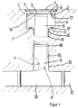
- FIG. 1 and 2 show a revision shaft system with a horizontal underground pipe 12 , into which a T-piece 10 is inserted.
- the base leg 13 of the T-piece 10 is directed vertically upwards and is connected via a socket connection 15 to a lower first shaft section 11, which consists of a cylindrical tube.
- the length of the first shaft section 11 can be freely selected according to the local requirements.
- the first shaft section 11 merges into a second shaft section 4 lying above it via a second sleeve connection 16 .
- the second shaft section 4 also consists of a tube, the diameter of which is larger than the diameter of the first shaft section 11 .
- the tubes of the shaft sections 4 , 11 can consist of soil-resistant and / or wastewater-resistant plastic.
- the upper shaft section 4 can be closed by a cover 1 . In particular in the event that the inspection shaft is located in the street area, the cover 1 preferably has ventilation openings, not shown in detail.
- a tubular element 7 , 8 , 9 is inserted into the shaft sections 4, 11 and guided in the lower shaft section 11 .
- the tubular element 7, 8, 9 consists of a bend 9 , a cylindrical tube 8 adjoining it at the top and a ring element 7 adjoining it at the top.
- the elbow 9 , the tube 8 and the ring member 7 are each connected by sleeve connections 14 , 18 .
- the manifold 9 is open in its lower area to its left side A according to FIG. 1 or FIG. 2. Its right side B is closed and circular or elliptical.
- the bend B of the elbow 9 attaches to the cylindrical wall of the tube 8 and forms an essentially 90 ° deflection which essentially merges into the longitudinal orientation of the main line 12 .
- the described design of the tubular element 7 , 8 , 9 with the socket connections 14 , 18 enables a variable length adjustment which can be adapted to the respective spatial conditions.
- each of the holders 2 , 3 has an upwardly open notch 17 or groove.
- Two upstanding handles 5 are attached to the ring element 7 . Furthermore, two diametrically opposite mounting attachments 6 project laterally outwards from the ring element 7 . These bracket attachments 6 serve to rest on the lower brackets 3 (FIG. 2) or the upper brackets 2 (FIG. 1).
- the tubular element 7 , 8 , 9 which serves as a guide, is in an upper position.
- the bracket attachments 6 lie on the upper brackets 2 and engage in the notches 17 .
- the tubular element 7 , 8 , 9 with its elbow 9 is completely pulled out of the cross section of the base line 12 , so that an unimpeded flow through the base line is possible.
- the mounting attachments 6 emerge from the engagement area 17 of the upper brackets 2 , so that the tubular element 7, 8 , 9 now lower downward and can be rotated back into its original rotational position until its mounting attachments 6 come to rest on the lower mounting 3 .
- the elbow 9 protrudes into the cross section of the main pipe 12 .
- the lower end of the elbow 9 does not touch the sole of the T-piece 10 , but leaves a space free, for example to allow rinsing water to flow off against the direction of flow when cleaning the main line 12 .
- tubular element 7 , 8 , 9 can be rotated such that the open side A of the elbow 9 is oriented either in the direction of flow or against the direction of flow of the main line 12 .
- the tubular element 7 , 8 , 9 is normally in its upper position. If testing or cleaning work is carried out, for example, with a flexible TV access camera or a flexible cleaning spiral, the cover 1 is lifted off and the tubular element 7 , 8 , 9 is brought into its lower position. It is rotated in the desired direction of the base line 12 . Now a TV inspection camera or a flexible cleaning spiral can be inserted into the tubular element 7, 8 , 9 . If the camera or the spiral reaches the elbow 9 , it is deflected by the elbow in the desired direction of the base line 12 .
- the tubular element 7, 8 , 9 thus serves as a guide for a flexible cleaning or testing device.
- a flexible high-pressure hose 19 is indicated, which is inserted into the tubular element 7, 8 , 9 from above and is deflected by the elbow 9 to the left into the base line 12 .
- a spray nozzle 20 At the end of the high-pressure hose 19 there is a spray nozzle 20 , which is used to clean the base line 12 .
Landscapes
- Health & Medical Sciences (AREA)
- Life Sciences & Earth Sciences (AREA)
- Engineering & Computer Science (AREA)
- Hydrology & Water Resources (AREA)
- Public Health (AREA)
- Water Supply & Treatment (AREA)
- Sewage (AREA)
Applications Claiming Priority (2)
| Application Number | Priority Date | Filing Date | Title |
|---|---|---|---|
| DE19705377 | 1997-02-12 | ||
| DE1997105377 DE19705377C1 (de) | 1997-02-12 | 1997-02-12 | Revisionsschachtsystem und Einführungshilfe |
Publications (1)
| Publication Number | Publication Date |
|---|---|
| EP0859094A1 true EP0859094A1 (fr) | 1998-08-19 |
Family
ID=7820043
Family Applications (1)
| Application Number | Title | Priority Date | Filing Date |
|---|---|---|---|
| EP98102306A Withdrawn EP0859094A1 (fr) | 1997-02-12 | 1998-02-11 | Système de puits d'accès et moyen d'introduction |
Country Status (2)
| Country | Link |
|---|---|
| EP (1) | EP0859094A1 (fr) |
| DE (1) | DE19705377C1 (fr) |
Families Citing this family (4)
| Publication number | Priority date | Publication date | Assignee | Title |
|---|---|---|---|---|
| DE29907841U1 (de) * | 1999-05-03 | 1999-07-08 | Kunststoffröhren Sendenhorst GmbH, 48324 Sendenhorst | Abwasserkontrolleinrichtung |
| CN107740490A (zh) * | 2017-09-13 | 2018-02-27 | 杭州市富阳区和博管道研究所 | 城市综合管廊排水管检修方法 |
| CN114405941B (zh) * | 2021-03-18 | 2023-03-24 | 广西大藤峡实业管理有限公司 | 一种水利用管道清理系统 |
| CN115596015B (zh) * | 2022-09-28 | 2024-09-27 | 中国一冶集团有限公司 | 一种机械式防坠井盖系统及工作方法 |
Citations (5)
| Publication number | Priority date | Publication date | Assignee | Title |
|---|---|---|---|---|
| DE3046496A1 (de) * | 1980-12-10 | 1982-07-15 | Karl 8901 Welden Wiedemann | Vorrichtung zum kanalreinigen |
| DE3324525C1 (de) * | 1983-07-07 | 1985-02-28 | Georg Dipl.-Ing.(FH) 8087 Türkenfeld Klaß | Umlenk- und Leitvorrichtung fuer einen eine Kanalreinigungsduese tragenden Hochdruckwasserschlauch |
| DE3604856A1 (de) * | 1986-02-15 | 1987-08-20 | Rudolph Karl Ulrich Prof Dr Dr | Kontroll- und spueleinrichtung an einer abwasserleitung |
| DE8713195U1 (de) * | 1987-10-01 | 1987-12-03 | Jeschke, Immanuel, 3203 Sarstedt | Vorrichtung zum Absperren von Gastransportleitungen |
| US5462077A (en) * | 1994-03-31 | 1995-10-31 | Brooklyn Union Gas Co. | Apparatus and method for shutting off fluid flow in a pipe main |
Family Cites Families (2)
| Publication number | Priority date | Publication date | Assignee | Title |
|---|---|---|---|---|
| DE297310C (fr) * | ||||
| US3474484A (en) * | 1968-04-24 | 1969-10-28 | Central Eng Co Inc | Sewer cleaner suction pipe |
-
1997
- 1997-02-12 DE DE1997105377 patent/DE19705377C1/de not_active Expired - Fee Related
-
1998
- 1998-02-11 EP EP98102306A patent/EP0859094A1/fr not_active Withdrawn
Patent Citations (5)
| Publication number | Priority date | Publication date | Assignee | Title |
|---|---|---|---|---|
| DE3046496A1 (de) * | 1980-12-10 | 1982-07-15 | Karl 8901 Welden Wiedemann | Vorrichtung zum kanalreinigen |
| DE3324525C1 (de) * | 1983-07-07 | 1985-02-28 | Georg Dipl.-Ing.(FH) 8087 Türkenfeld Klaß | Umlenk- und Leitvorrichtung fuer einen eine Kanalreinigungsduese tragenden Hochdruckwasserschlauch |
| DE3604856A1 (de) * | 1986-02-15 | 1987-08-20 | Rudolph Karl Ulrich Prof Dr Dr | Kontroll- und spueleinrichtung an einer abwasserleitung |
| DE8713195U1 (de) * | 1987-10-01 | 1987-12-03 | Jeschke, Immanuel, 3203 Sarstedt | Vorrichtung zum Absperren von Gastransportleitungen |
| US5462077A (en) * | 1994-03-31 | 1995-10-31 | Brooklyn Union Gas Co. | Apparatus and method for shutting off fluid flow in a pipe main |
Also Published As
| Publication number | Publication date |
|---|---|
| DE19705377C1 (de) | 1998-07-30 |
Similar Documents
| Publication | Publication Date | Title |
|---|---|---|
| DE3204888C2 (de) | Kontrollschacht für eine unterirdische Abwasser-Kanalisation | |
| CH492839A (de) | Satz von Teilen zur Bildung einer Erd- und Oberflächen-Entwässerungsanlage | |
| EP0457319B1 (fr) | Manchon d'étanchéité et son application | |
| DE19705377C1 (de) | Revisionsschachtsystem und Einführungshilfe | |
| EP1717380B1 (fr) | Pièce de raccordement pour brancher un article sanitaire | |
| EP3686366B1 (fr) | Dispositif de conduite d'évacuation | |
| DE102013112970A1 (de) | Ablaufvorrichtung sowie Innenrohrelement zum zumindest teilweisen Einsetzen in einen Einlaufstutzen einer Ablaufvorrichtung | |
| EP2636812A1 (fr) | Procédé et dispositif de drainage des eaux pluviales de toit sous la forme d'un drainage principal et d'un drainage de secours | |
| DE3716973A1 (de) | Rohr- und dichtungs-garnitur | |
| DE29616503U1 (de) | Ins Erdreich einbaubarer Kontroll- und Verteilerschacht | |
| DE8902168U1 (de) | Ablauf-Anschlußbogen für Sanitäreinrichtungen | |
| EP3795759A2 (fr) | Système de tubes de protection | |
| DE10013805B4 (de) | Steigleitungsanordnung mit einer an unterschiedlichste Bodensetzungen anpaßbaren Schachtabdeckung | |
| CH658695A5 (en) | Shaft cup device | |
| DE3406505C2 (fr) | ||
| DE10028256B4 (de) | Variabler Grundleitungsanschluss | |
| DE19927020C2 (de) | Verfahren zum unterirdischen Verlegen von Entwässerungskanälen und Preßschacht zur Durchführung des Verfahrens | |
| DE10240906B4 (de) | Kanalschacht für Abwasser-Kanalisation | |
| DE102010011868B4 (de) | Abwasserschacht | |
| CH684546A5 (de) | Rohr zum Rohr-in-Rohr-Sanieren von Rohrleitungen sowie Verfahren zum Einbauen dieses Rohres und Vorrichtung zur Ausführung des Verfahrens. | |
| DE20214573U1 (de) | Vorrichtung zum Einleiten von wässrigen Suspensionen organischer Stoffe in ein Vererdungsbecken | |
| DE2203160B2 (de) | Stirnwand für einen Durchlaß eines Wasserlaufs | |
| DE19737720B4 (de) | Verfahren und Vorrichtung zur Herstellung einer Flüssigkeitsleitung mit einem eingebauten Funktionsbauteil | |
| DE202020003926U1 (de) | Schlauchumlenkung | |
| DE102014115646A1 (de) | Anlage zum Verlegen von Leerrohren in Abwasserkanälen |
Legal Events
| Date | Code | Title | Description |
|---|---|---|---|
| PUAI | Public reference made under article 153(3) epc to a published international application that has entered the european phase |
Free format text: ORIGINAL CODE: 0009012 |
|
| AK | Designated contracting states |
Kind code of ref document: A1 Designated state(s): AT CH DE ES FR GB IT LI NL PT SE |
|
| AX | Request for extension of the european patent |
Free format text: AL;LT;LV;MK;RO;SI |
|
| 17P | Request for examination filed |
Effective date: 19990206 |
|
| AKX | Designation fees paid |
Free format text: AT CH DE ES FR GB IT LI NL PT SE |
|
| RBV | Designated contracting states (corrected) |
Designated state(s): AT CH DE ES FR GB IT LI NL PT SE |
|
| 17Q | First examination report despatched |
Effective date: 20020802 |
|
| GRAP | Despatch of communication of intention to grant a patent |
Free format text: ORIGINAL CODE: EPIDOSNIGR1 |
|
| RTI1 | Title (correction) |
Free format text: MANHOLE SHAFT SYSTEM |
|
| STAA | Information on the status of an ep patent application or granted ep patent |
Free format text: STATUS: THE APPLICATION IS DEEMED TO BE WITHDRAWN |
|
| 18D | Application deemed to be withdrawn |
Effective date: 20040614 |