EP0859098B1 - Maçonnerie avec système d'armature intégrée - Google Patents
Maçonnerie avec système d'armature intégrée Download PDFInfo
- Publication number
- EP0859098B1 EP0859098B1 EP98500042A EP98500042A EP0859098B1 EP 0859098 B1 EP0859098 B1 EP 0859098B1 EP 98500042 A EP98500042 A EP 98500042A EP 98500042 A EP98500042 A EP 98500042A EP 0859098 B1 EP0859098 B1 EP 0859098B1
- Authority
- EP
- European Patent Office
- Prior art keywords
- reinforcement
- bars
- longitudinal
- masonry wall
- wall
- Prior art date
- Legal status (The legal status is an assumption and is not a legal conclusion. Google has not performed a legal analysis and makes no representation as to the accuracy of the status listed.)
- Expired - Lifetime
Links
Images




Classifications
-
- E—FIXED CONSTRUCTIONS
- E04—BUILDING
- E04B—GENERAL BUILDING CONSTRUCTIONS; WALLS, e.g. PARTITIONS; ROOFS; FLOORS; CEILINGS; INSULATION OR OTHER PROTECTION OF BUILDINGS
- E04B2/00—Walls, e.g. partitions, for buildings; Wall construction with regard to insulation; Connections specially adapted to walls
- E04B2/02—Walls, e.g. partitions, for buildings; Wall construction with regard to insulation; Connections specially adapted to walls built-up from layers of building elements
- E04B2/04—Walls having neither cavities between, nor in, the solid elements
- E04B2/06—Walls having neither cavities between, nor in, the solid elements using elements having specially-designed means for stabilising the position
-
- E—FIXED CONSTRUCTIONS
- E04—BUILDING
- E04B—GENERAL BUILDING CONSTRUCTIONS; WALLS, e.g. PARTITIONS; ROOFS; FLOORS; CEILINGS; INSULATION OR OTHER PROTECTION OF BUILDINGS
- E04B2/00—Walls, e.g. partitions, for buildings; Wall construction with regard to insulation; Connections specially adapted to walls
- E04B2/02—Walls, e.g. partitions, for buildings; Wall construction with regard to insulation; Connections specially adapted to walls built-up from layers of building elements
- E04B2/04—Walls having neither cavities between, nor in, the solid elements
- E04B2/06—Walls having neither cavities between, nor in, the solid elements using elements having specially-designed means for stabilising the position
- E04B2/10—Walls having neither cavities between, nor in, the solid elements using elements having specially-designed means for stabilising the position by filling material with or without reinforcements in small channels in, or in grooves between, the elements
-
- E—FIXED CONSTRUCTIONS
- E04—BUILDING
- E04C—STRUCTURAL ELEMENTS; BUILDING MATERIALS
- E04C5/00—Reinforcing elements, e.g. for concrete; Auxiliary elements therefor
- E04C5/01—Reinforcing elements of metal, e.g. with non-structural coatings
-
- E—FIXED CONSTRUCTIONS
- E04—BUILDING
- E04C—STRUCTURAL ELEMENTS; BUILDING MATERIALS
- E04C5/00—Reinforcing elements, e.g. for concrete; Auxiliary elements therefor
- E04C5/01—Reinforcing elements of metal, e.g. with non-structural coatings
- E04C5/06—Reinforcing elements of metal, e.g. with non-structural coatings of high bending resistance, i.e. of essentially three-dimensional [3D] extent, e.g. lattice girders
- E04C5/065—Light-weight girders, e.g. with precast parts
-
- E—FIXED CONSTRUCTIONS
- E04—BUILDING
- E04C—STRUCTURAL ELEMENTS; BUILDING MATERIALS
- E04C5/00—Reinforcing elements, e.g. for concrete; Auxiliary elements therefor
- E04C5/16—Auxiliary parts for reinforcements, e.g. connectors, spacers, stirrups
-
- E—FIXED CONSTRUCTIONS
- E04—BUILDING
- E04C—STRUCTURAL ELEMENTS; BUILDING MATERIALS
- E04C5/00—Reinforcing elements, e.g. for concrete; Auxiliary elements therefor
- E04C5/16—Auxiliary parts for reinforcements, e.g. connectors, spacers, stirrups
- E04C5/162—Connectors or means for connecting parts for reinforcements
- E04C5/163—Connectors or means for connecting parts for reinforcements the reinforcements running in one single direction
Definitions
- the present invention provides a masonry wall with an integral reinforcing system, particularly with regards to the vertical reinforcement of the wall.
- the system involves reinforcement set in housing or channels provided within the wall and this reinforcement together with its corresponding anchorage and components may be used as framework or formwork in order to form an integral system which, in accordance with the established design theory, is always set in the precise position to allow the wall to work effectively in accordance with the design values of stress for the construction.
- This integral reinforcing system is applicable to all types of masonry and does not affect the properties of the wall in those areas which do not require reinforcing, and will in no way affect the exposed face of the wall.
- this patent does not cover certain significant aspects related to bricklaying techniques, and specifically that regarding: the form of the prefabricated longitudinal reinforcement; the anchors and supplementary components necessary for an integral reinforcing system and which ensure quick, simple and efficient construction; and the correct positioning and spacing of the longitudinal reinforcement with regard to the two faces of the wall.
- German patent DE-A-19 13 379 also discloses a reinforcing system.
- the integral reinforcing system proposed by this invention effectively covers the requirements indicated above and, as such, is focused on the longitudinal reinforcement, the anchors for the same and the series of supplementary elements.
- the longitudinal reinforcement may be applied to different types of reinforced masonry, namely.
- this reinforcement may also serve as guide frame within the masonry, which is accessible from the unexposed face of the wall (or the exposed face if so required), and which may be used to hold certain types of anchors and/or connectors. Indeed, these connectors could also be fitted to the free ends (upper and lower) of the said void reinforcement.
- the anchors Once the anchors are fixed to the longitudinal reinforcement they may be then used to serve the following functions, to name but a few:
- the longitudinal reinforcement is made up of one or several, individual or grouped longitudinal elements set parallel to each other at constant distances and joined by separators and spacers which may or may not be incorporated as part of the prefabricated component. These separators and spacers retain the parallel form of the reinforcement for the purposes of handling and its vertical placement within the wall near to both masonry faces during the construction.
- the longitudinal reinforcement and anchors are designed to perform satisfactorily whether embedded in mortar, concrete, adhesives or cement glue and may even be placed completely or partially "free” of any binding material.
- the longitudinal reinforcement and the connectors usually form an integral and resistant framework which may be suitably placed within the wall by the bricklayer. However, sometimes these two components may be fixed together by hand either before being placed in the wall or once the vertical reinforcement has been placed in the wall.
- the anchors are designed as a separate item which are fixed by hand by the bricklayer at a specific height in accordance with the characteristics of the item to support and/or be supported. These anchors could also be designed with a certain capacity for sliding movement up or down the vertical guide of the void reinforcement.
- the supplementary components while apparently of a secondary nature, may often form an essential part of the system if it is to work correctly.
- the said reinforcement (1) may be formed by parallel longitudinal bars (5) which are suitably spaced and joined by connectors (6) which may be laid out in the zigzag form shown in figure 1, and with double longitudinal bars (5) or single bars. These connectors may be eliminated when the length of the reinforcement is very short, the bars may be joined together by a curved end piece (7) as shown in figure 2, moveable connectors (8) may be employed as shown in figure 3 and placed by the bricklayer himself, these latter connectors, which are manually fixed to the wall reinforcement, are made from plate angled at each end, a longitudinal cut being made in each angle and the sections turned asymmetrically and notched to adapt to the parallel and longitudinal wires or bars (1).
- These said moveable connectors may also take the form of that indicated by (9) in figure 4 where a longitudinal plate is provided with semi-circular notches (10) which are designed to slot onto the main reinforcing bars (5).
- the connectors may be joined within the same plane of the vertical reinforcement or on the sides of the same.
- the connectors (11) may also be formed in a continuous strip which is then separated by the bricklayer, as in the form of the sinuously shaped rod shown in figure 5, which is subsequently split up into suitable lengths to suit the spacing of the reinforcing bars.
- an anchor plate (15') this being a flat rectangular plate which lies horizontally and is simply fixed to the two vertical bars (5) of the reinforcement (1) by way of two notches stamped in the end of the plate in the form of a 'T'.
- the said plate (15') is also provided with a longitudinal slot (20') which allows it to be fixed to a floor slab or horizontal surface as required.
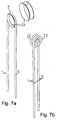
- the reinforcement (1) may also be connected at the ends, as is illustrated by the anchor (21) shown in figure 7a.
- This anchor consists of an externally notched sleeve or ring which houses the semi-circular upper section (7) closing the ends of the two bars (5) to the reinforcement.
- the said sleeve (21) may be provided with two parallel circumferential notches for double reinforcing bars, or may simply be made in the form of a cylinder.
- reinforcing bars themselves (5) may be looped (22) to form an anchorage in place of the ring (21), thereby eliminating the need for any additional element and subsequently be held by any suitable horizontal support.
- the anchorage to the reinforcement (1) is made at the lower end of the same, in such a way that the double reinforcing bar (5) is set on the surface of the floor slab while the longer reinforcing bar (5') is set against the side of the same, the said reinforcement (1) being fixed in position by way of a bracket (29) which clamps the reinforcement and is bolted together (30) and then, in turn, fixed to the floor slab (28) by a threaded pin (31) as illustrated in the said figure.
- the system is then completed with the said supplementary elements, such as the support profile (34) shown in figure 8 which is designed to slot on to the reinforcement (1) by way of horizontal grooves (35) set into the lower section of the profile, thereby allowing the said profile (34) to serve as the starting support for overhanging brick or blockwork.
- Other supplementary elements include; retention anchors for rising parapets of balconies or roofs; hanging brackets which may serve to support the housing for blinds or other window coverings; and plumb and levelling lines particularly in the manual erection of the brick or blockwork, and which obviously allow for adjustment within the direction of the three axes of the wall.
- Figure 9 shows a type of end anchorage where the longitudinal bars (5) of reinforcement (1) are bolted to an anchor plate (37).
- this system also allows the prefabrication of longitudinal reinforcement using only one component, and therefore one material unit. In this case there is no difference between the connectors and the vertical reinforcement. This would include plates bent to form open or closed sections, with plate of greater or lesser gauge and draw. Double reinforcement may be "U” shaped, cross the void in the form of an "X”, or vertically overlap, as in the traditional form of bars in reinforced concrete, in order to give longitudinal continuity to the reinforcement.
Landscapes
- Engineering & Computer Science (AREA)
- Architecture (AREA)
- Civil Engineering (AREA)
- Structural Engineering (AREA)
- Physics & Mathematics (AREA)
- Electromagnetism (AREA)
- Reinforcement Elements For Buildings (AREA)
- Rod-Shaped Construction Members (AREA)
- Working Measures On Existing Buildindgs (AREA)
- Sewage (AREA)
Claims (8)
- Mur de maçonnerie avec un système de renfort intégral qui fournit un jeu de renforcement vertical des deux côtés desdits murs, et placé dans une série de vides à l'intérieur des briques ou bâtiment, ouvert du côté non exposé, ayant quatre éléments de base : renforcement longitudinal ; connecteurs transversaux et / ou pièces d'écartement audit renforcement ; ancrages latéraux et / ou ancrages terminaux et ancrages de retenue, caractérisé en ce queles ancrages latéraux sont composés d'une plaque plate rectangulaire (15') qui peut être fixée au renforcement (1) au moyen de deux entailles estampées à l'extrémité de la plaque sous forme de « T » (19) et qui peut glisser vers le haut et vers le bas des barres longitudinales (5), ladite plaque (15') étant pourvue d'une rainure longitudinale (20') qui lui permet d'être fixée à un support selon les besoins.les ancrages terminaux sont composés d'anneaux cannelés (21), de cylindres ou d'autres éléments similaires qui peuvent s'adapter à la fermeture latérale et terminale (7) des barres longitudinales (5) du renforcement (1), oul'ancrage terminal est composé de boucles des extrémités (22) des barres de renforcement (5) elles-mêmes.les ancrages de retenue consistent en un profil de support (34), conçu pour s'insérer dans le renforcement (1) au moyen de rainures horizontales (35).
- Le mur de maçonnerie tel que décrit à la revendication 1, caractérisé parce que le renforcement longitudinal (1) est composé de barres, câbles, fonds, plaques, tubes et similaires, sous différentes formes et section et est simple, double ou multiple avec des extrémités ouvertes ou des extrémités repliées (7) de façon à former un élément unique.
- Le mur de maçonnerie tel que décrit à la revendication 1, caractérisé en ce que les connecteurs transversaux et / ou pièces d'écartement sont composés de barres ou plaques (6) qui sont directement soudées ou fixées aux barres verticales (5) du renforcement (1) ou bien sur le plan du renforcement ou sur l'autre côté, dans une position perpendiculaire ou en angle ou peuvent être des éléments indépendants qui sont fixés au renforcement sur place par le maçon.
- Le mur de maçonnerie tel que décrit à la revendication 3, caractérisé en ce que les connecteurs indépendants et / ou pièces d'écartement sont composés de plaques (8) en angle à chaque extrémité avec une entaille longitudinale faite à chaque angle et la courbure des sections asymétriquement et intérieurement encochée pour s'adapter aux barres longitudinales (5) du renforcement (1).
- Le mur de maçonnerie tel que décrit à la revendication 3, caractérisé en ce que les connecteurs indépendants et / ou pièces d'écartement sont composés de plaques (9) avec des bords encochés (10) qui s'insèrent dans les barres (5) du renforcement (1).
- Le mur de maçonnerie tel que décrit à la revendication 3, caractérisé en ce que les connecteurs indépendants et / ou pièces d'écartement forment une bande continue de longueur indéfinie sous forme d'une baguette sinueuse (11), qui est fendue en plusieurs longueurs appropriées par le maçon pour s'adapter à l'écartement des barres (5) du renforcement (1).
- Le mur de maçonnerie tel que décrit à la revendication 1, caractérisé en ce que le renforcement longitudinal est maintenu à l'extrémité inférieure et / ou supérieure de celui-ci, et en ce que les barres longitudinales intérieures (5) reposent sur la dalle (28) tandis que les barres extérieures plus longues (5') sont placées contre le bord de ladite dalle, le renforcement étant fixé par un support de fixation (29) qui est fixé latéralement au renforcement (1) par un boulon transversal (30) et, à son tour, attaché à la dalle (28) au moyen d'une cheville filetée (31).
- Le mur de maçonnerie tel que décrit aux revendications 1 à 15, caractérisé en ce que les extrémités des barres (5) du renforcement (1) sont filetées pour recevoir une plaque d'ancrage cerclée (37) qui est attachée aux barres (5) à travers des perforations (38).
Applications Claiming Priority (2)
| Application Number | Priority Date | Filing Date | Title |
|---|---|---|---|
| ES9700309 | 1997-02-14 | ||
| ES009700309A ES2143357B1 (es) | 1997-02-14 | 1997-02-14 | Sistema integral de armado de muros de fabrica. |
Publications (2)
| Publication Number | Publication Date |
|---|---|
| EP0859098A1 EP0859098A1 (fr) | 1998-08-19 |
| EP0859098B1 true EP0859098B1 (fr) | 2005-11-02 |
Family
ID=8298256
Family Applications (1)
| Application Number | Title | Priority Date | Filing Date |
|---|---|---|---|
| EP98500042A Expired - Lifetime EP0859098B1 (fr) | 1997-02-14 | 1998-02-13 | Maçonnerie avec système d'armature intégrée |
Country Status (4)
| Country | Link |
|---|---|
| EP (1) | EP0859098B1 (fr) |
| AT (1) | ATE308649T1 (fr) |
| DE (1) | DE69832117T2 (fr) |
| ES (2) | ES2143357B1 (fr) |
Families Citing this family (6)
| Publication number | Priority date | Publication date | Assignee | Title |
|---|---|---|---|---|
| AU5643199A (en) * | 1998-09-22 | 2000-04-10 | Consolidated Bullion Limited | Bar with a plurality of sections capable to be severed from one another |
| ES2198997B1 (es) * | 2000-05-11 | 2005-08-01 | J.A.C. Y Asociados, Arquitectura S.L. | Procedimiento para la rehabilitacion de fachadas de fabrica deterioradas y con patologias extremas mediante muros cortina ventilados de fabrica sin afectar al uso continuo del edificio. |
| ES2257893B1 (es) * | 2003-04-08 | 2007-05-16 | Josep Maria Adell Argiles | Anclaje multiuso para muros armados o sin armar. |
| GB2460674A (en) * | 2008-06-04 | 2009-12-09 | Wembley Innovation Ltd | Masonry bracket |
| GB2485397B (en) * | 2010-11-12 | 2013-07-03 | Wembley Innovation Ltd | Reinforced masonry panel structures |
| KR101978604B1 (ko) * | 2018-07-30 | 2019-05-14 | 오정훈 | 건축용블록 조적가이드 |
Family Cites Families (8)
| Publication number | Priority date | Publication date | Assignee | Title |
|---|---|---|---|---|
| GB221668A (en) * | 1923-10-19 | 1924-09-18 | William Mccaughan | Improvements relating to the construction of walls, for buildings or other structures |
| CH423167A (de) * | 1965-05-03 | 1966-10-31 | Brandestini Antonio | Verfahren zur Herstellung eines bewehrten Mauerwerks |
| FR1457422A (fr) * | 1965-07-27 | 1966-01-24 | Impresa A Bellini & C S P A | Procédé pour stabiliser l'armature métallique dans les éléments en béton armé au moyen d'étriers transversaux |
| FR1451695A (fr) * | 1965-10-20 | 1966-01-07 | Mur de pierre renforcé | |
| DE1913379A1 (de) * | 1969-03-17 | 1970-09-24 | Kurt Mauerer | Steine,die einen echten Ersatz fuer auf der Baustelle vergossenen Stahlbeton ergeben |
| AU606565B2 (en) * | 1988-05-05 | 1991-02-07 | N.V. Bekaert S.A. | Reinforcing apparatus for a masonry wall, as well as masonry wall |
| CH686838A5 (de) * | 1993-04-14 | 1996-07-15 | Verband Schweizerische Ziegeli | Baustein. |
| ES2122884B1 (es) | 1995-09-29 | 1999-05-01 | Adell Argiles Josep Maria | Metodo de albañileria integral con posibilidad de armado tridimensional y piezas constructivas para dicho metodo. |
-
1997
- 1997-02-14 ES ES009700309A patent/ES2143357B1/es not_active Expired - Fee Related
-
1998
- 1998-02-13 AT AT98500042T patent/ATE308649T1/de not_active IP Right Cessation
- 1998-02-13 EP EP98500042A patent/EP0859098B1/fr not_active Expired - Lifetime
- 1998-02-13 DE DE69832117T patent/DE69832117T2/de not_active Expired - Lifetime
-
2002
- 2002-09-19 ES ES200202151A patent/ES2234366B1/es not_active Expired - Fee Related
Also Published As
| Publication number | Publication date |
|---|---|
| ES2143357A1 (es) | 2000-05-01 |
| DE69832117D1 (de) | 2005-12-08 |
| ES2143357B1 (es) | 2000-12-01 |
| ES2234366B1 (es) | 2006-10-01 |
| ES2234366A1 (es) | 2005-06-16 |
| ATE308649T1 (de) | 2005-11-15 |
| DE69832117T2 (de) | 2006-08-17 |
| EP0859098A1 (fr) | 1998-08-19 |
Similar Documents
| Publication | Publication Date | Title |
|---|---|---|
| US7114296B2 (en) | Temporary bracing system for insulated wall form and method | |
| EP2313575B1 (fr) | Équerre de maçonnerie, système et procédé de construction | |
| US1729935A (en) | Wall anchor | |
| US20100071306A1 (en) | Reinforcing bracket for use with insulated concrete forms | |
| EA010209B1 (ru) | Сборная железобетонная колонна, стык сборных колонн и способ выполнения стыка | |
| US6865857B1 (en) | Integral reinforcing system for masonry walls | |
| EP0859098A1 (fr) | Système d'armature intégrée pour maçonnerie | |
| US6526721B1 (en) | Fluid-impervious barrier/keyway form support apparatus, system and related method | |
| PL181551B1 (pl) | Sposób wznoszenia wysokich budynków i urzadzenie regulacyjne do wznoszenia wysokich budynków PL | |
| CN217631737U (zh) | 一种适用性强的可调节预制装配的嵌入式围墙结构 | |
| GB1598011A (en) | Construction comprising reinforced concrete cavity slabs | |
| JP2001172984A (ja) | アンカーボルト保持金具 | |
| SK337292A3 (en) | Method of fixing, in particular cover boards by their additional fastening and a fixing system | |
| RU2387763C1 (ru) | Способ возведения монолитных стен жилых домов, зданий и сооружений в комбинированной опалубке | |
| KR20110002820U (ko) | 파이프 고정구 | |
| TW577953B (en) | Formwork girt | |
| JP2000017841A (ja) | 鉄筋支持具、これを用いたコンクリート壁、及びその施工方法 | |
| JP3359145B2 (ja) | 止水板設置方法 | |
| JPH0841985A (ja) | プレキャスト梁と柱の緊結方法 | |
| KR970006113Y1 (ko) | 철근받침용 스페이서의 결속구조 | |
| JP2003278272A6 (ja) | プレキャストコンクリート柱及びその施工方法 | |
| SU857380A1 (ru) | Перекрытие | |
| JPH09302846A (ja) | ラス型枠位置決め金具および位置決め工法 | |
| EP0505329A1 (fr) | Montant pour marquer l'ouverture d'une porte dans la construction de murs en maçonnerie, pouvant supporter le châssis de la porte | |
| JPH04124375A (ja) | 大引材支持具 |
Legal Events
| Date | Code | Title | Description |
|---|---|---|---|
| PUAI | Public reference made under article 153(3) epc to a published international application that has entered the european phase |
Free format text: ORIGINAL CODE: 0009012 |
|
| AK | Designated contracting states |
Kind code of ref document: A1 Designated state(s): AT BE CH DE DK ES FI FR GB IT LI NL PT SE |
|
| AX | Request for extension of the european patent |
Free format text: AL;LT;LV;MK;RO;SI |
|
| 17P | Request for examination filed |
Effective date: 19990218 |
|
| AKX | Designation fees paid |
Free format text: AT BE CH DE DK ES FI FR GB IT LI NL PT SE |
|
| RBV | Designated contracting states (corrected) |
Designated state(s): AT BE CH DE DK ES FI FR GB IT LI NL PT SE |
|
| 17Q | First examination report despatched |
Effective date: 20021105 |
|
| GRAP | Despatch of communication of intention to grant a patent |
Free format text: ORIGINAL CODE: EPIDOSNIGR1 |
|
| RTI1 | Title (correction) |
Free format text: MASONRY WALL WITH AN INTEGRAL REINFORCING SYSTEM |
|
| GRAS | Grant fee paid |
Free format text: ORIGINAL CODE: EPIDOSNIGR3 |
|
| GRAA | (expected) grant |
Free format text: ORIGINAL CODE: 0009210 |
|
| AK | Designated contracting states |
Kind code of ref document: B1 Designated state(s): AT BE CH DE DK ES FI FR GB IT LI NL PT SE |
|
| PG25 | Lapsed in a contracting state [announced via postgrant information from national office to epo] |
Ref country code: LI Free format text: LAPSE BECAUSE OF FAILURE TO SUBMIT A TRANSLATION OF THE DESCRIPTION OR TO PAY THE FEE WITHIN THE PRESCRIBED TIME-LIMIT Effective date: 20051102 Ref country code: CH Free format text: LAPSE BECAUSE OF FAILURE TO SUBMIT A TRANSLATION OF THE DESCRIPTION OR TO PAY THE FEE WITHIN THE PRESCRIBED TIME-LIMIT Effective date: 20051102 Ref country code: AT Free format text: LAPSE BECAUSE OF FAILURE TO SUBMIT A TRANSLATION OF THE DESCRIPTION OR TO PAY THE FEE WITHIN THE PRESCRIBED TIME-LIMIT Effective date: 20051102 |
|
| REG | Reference to a national code |
Ref country code: GB Ref legal event code: FG4D |
|
| REG | Reference to a national code |
Ref country code: CH Ref legal event code: EP |
|
| REF | Corresponds to: |
Ref document number: 69832117 Country of ref document: DE Date of ref document: 20051208 Kind code of ref document: P |
|
| PG25 | Lapsed in a contracting state [announced via postgrant information from national office to epo] |
Ref country code: SE Free format text: LAPSE BECAUSE OF FAILURE TO SUBMIT A TRANSLATION OF THE DESCRIPTION OR TO PAY THE FEE WITHIN THE PRESCRIBED TIME-LIMIT Effective date: 20060202 Ref country code: DK Free format text: LAPSE BECAUSE OF FAILURE TO SUBMIT A TRANSLATION OF THE DESCRIPTION OR TO PAY THE FEE WITHIN THE PRESCRIBED TIME-LIMIT Effective date: 20060202 |
|
| PG25 | Lapsed in a contracting state [announced via postgrant information from national office to epo] |
Ref country code: ES Free format text: LAPSE BECAUSE OF FAILURE TO SUBMIT A TRANSLATION OF THE DESCRIPTION OR TO PAY THE FEE WITHIN THE PRESCRIBED TIME-LIMIT Effective date: 20060213 |
|
| REG | Reference to a national code |
Ref country code: CH Ref legal event code: PL |
|
| ET | Fr: translation filed | ||
| PLBE | No opposition filed within time limit |
Free format text: ORIGINAL CODE: 0009261 |
|
| STAA | Information on the status of an ep patent application or granted ep patent |
Free format text: STATUS: NO OPPOSITION FILED WITHIN TIME LIMIT |
|
| 26N | No opposition filed |
Effective date: 20060803 |
|
| PGFP | Annual fee paid to national office [announced via postgrant information from national office to epo] |
Ref country code: NL Payment date: 20090220 Year of fee payment: 12 Ref country code: FI Payment date: 20090217 Year of fee payment: 12 |
|
| PGFP | Annual fee paid to national office [announced via postgrant information from national office to epo] |
Ref country code: GB Payment date: 20090211 Year of fee payment: 12 |
|
| PGFP | Annual fee paid to national office [announced via postgrant information from national office to epo] |
Ref country code: FR Payment date: 20090128 Year of fee payment: 12 |
|
| PGFP | Annual fee paid to national office [announced via postgrant information from national office to epo] |
Ref country code: PT Payment date: 20100211 Year of fee payment: 13 |
|
| PGFP | Annual fee paid to national office [announced via postgrant information from national office to epo] |
Ref country code: IT Payment date: 20100212 Year of fee payment: 13 |
|
| PGFP | Annual fee paid to national office [announced via postgrant information from national office to epo] |
Ref country code: DE Payment date: 20100429 Year of fee payment: 13 Ref country code: BE Payment date: 20100326 Year of fee payment: 13 |
|
| REG | Reference to a national code |
Ref country code: NL Ref legal event code: V1 Effective date: 20100901 |
|
| GBPC | Gb: european patent ceased through non-payment of renewal fee |
Effective date: 20100213 |
|
| REG | Reference to a national code |
Ref country code: FR Ref legal event code: ST Effective date: 20101029 |
|
| PG25 | Lapsed in a contracting state [announced via postgrant information from national office to epo] |
Ref country code: FI Free format text: LAPSE BECAUSE OF NON-PAYMENT OF DUE FEES Effective date: 20100213 |
|
| PG25 | Lapsed in a contracting state [announced via postgrant information from national office to epo] |
Ref country code: NL Free format text: LAPSE BECAUSE OF NON-PAYMENT OF DUE FEES Effective date: 20100901 Ref country code: FR Free format text: LAPSE BECAUSE OF NON-PAYMENT OF DUE FEES Effective date: 20100301 |
|
| REG | Reference to a national code |
Ref country code: DE Ref legal event code: R231 Ref document number: 69832117 Country of ref document: DE |
|
| PG25 | Lapsed in a contracting state [announced via postgrant information from national office to epo] |
Ref country code: GB Free format text: LAPSE BECAUSE OF NON-PAYMENT OF DUE FEES Effective date: 20100213 |
|
| PG25 | Lapsed in a contracting state [announced via postgrant information from national office to epo] |
Ref country code: DE Free format text: LAPSE BECAUSE OF THE APPLICANT RENOUNCES Effective date: 20110323 |
|
| REG | Reference to a national code |
Ref country code: PT Ref legal event code: MM4A Free format text: LAPSE DUE TO NON-PAYMENT OF FEES Effective date: 20110816 |
|
| BERE | Be: lapsed |
Owner name: *ADELL ARGILES JOSEP MARIA Effective date: 20110228 |
|
| PG25 | Lapsed in a contracting state [announced via postgrant information from national office to epo] |
Ref country code: PT Free format text: LAPSE BECAUSE OF NON-PAYMENT OF DUE FEES Effective date: 20110816 |
|
| PG25 | Lapsed in a contracting state [announced via postgrant information from national office to epo] |
Ref country code: BE Free format text: LAPSE BECAUSE OF NON-PAYMENT OF DUE FEES Effective date: 20110228 |
|
| PG25 | Lapsed in a contracting state [announced via postgrant information from national office to epo] |
Ref country code: IT Free format text: LAPSE BECAUSE OF NON-PAYMENT OF DUE FEES Effective date: 20110213 |