EP0859221A1 - Anordnung zur steuerung eines anzeigeinstruments - Google Patents
Anordnung zur steuerung eines anzeigeinstruments Download PDFInfo
- Publication number
- EP0859221A1 EP0859221A1 EP97927402A EP97927402A EP0859221A1 EP 0859221 A1 EP0859221 A1 EP 0859221A1 EP 97927402 A EP97927402 A EP 97927402A EP 97927402 A EP97927402 A EP 97927402A EP 0859221 A1 EP0859221 A1 EP 0859221A1
- Authority
- EP
- European Patent Office
- Prior art keywords
- electronic component
- component units
- meter
- meter unit
- unit
- Prior art date
- Legal status (The legal status is an assumption and is not a legal conclusion. Google has not performed a legal analysis and makes no representation as to the accuracy of the status listed.)
- Withdrawn
Links
Images


Classifications
-
- B—PERFORMING OPERATIONS; TRANSPORTING
- B60—VEHICLES IN GENERAL
- B60K—ARRANGEMENT OR MOUNTING OF PROPULSION UNITS OR OF TRANSMISSIONS IN VEHICLES; ARRANGEMENT OR MOUNTING OF PLURAL DIVERSE PRIME-MOVERS IN VEHICLES; AUXILIARY DRIVES FOR VEHICLES; INSTRUMENTATION OR DASHBOARDS FOR VEHICLES; ARRANGEMENTS IN CONNECTION WITH COOLING, AIR INTAKE, GAS EXHAUST OR FUEL SUPPLY OF PROPULSION UNITS IN VEHICLES
- B60K35/00—Instruments specially adapted for vehicles; Arrangement of instruments in or on vehicles
- B60K35/50—Instruments characterised by their means of attachment to or integration in the vehicle
-
- B—PERFORMING OPERATIONS; TRANSPORTING
- B60—VEHICLES IN GENERAL
- B60K—ARRANGEMENT OR MOUNTING OF PROPULSION UNITS OR OF TRANSMISSIONS IN VEHICLES; ARRANGEMENT OR MOUNTING OF PLURAL DIVERSE PRIME-MOVERS IN VEHICLES; AUXILIARY DRIVES FOR VEHICLES; INSTRUMENTATION OR DASHBOARDS FOR VEHICLES; ARRANGEMENTS IN CONNECTION WITH COOLING, AIR INTAKE, GAS EXHAUST OR FUEL SUPPLY OF PROPULSION UNITS IN VEHICLES
- B60K35/00—Instruments specially adapted for vehicles; Arrangement of instruments in or on vehicles
- B60K35/80—Arrangements for controlling instruments
-
- B—PERFORMING OPERATIONS; TRANSPORTING
- B60—VEHICLES IN GENERAL
- B60R—VEHICLES, VEHICLE FITTINGS, OR VEHICLE PARTS, NOT OTHERWISE PROVIDED FOR
- B60R16/00—Electric or fluid circuits specially adapted for vehicles and not otherwise provided for; Arrangement of elements of electric or fluid circuits specially adapted for vehicles and not otherwise provided for
- B60R16/02—Electric or fluid circuits specially adapted for vehicles and not otherwise provided for; Arrangement of elements of electric or fluid circuits specially adapted for vehicles and not otherwise provided for electric constitutive elements
- B60R16/023—Electric or fluid circuits specially adapted for vehicles and not otherwise provided for; Arrangement of elements of electric or fluid circuits specially adapted for vehicles and not otherwise provided for electric constitutive elements for transmission of signals between vehicle parts or subsystems
- B60R16/0231—Circuits relating to the driving or the functioning of the vehicle
- B60R16/0232—Circuits relating to the driving or the functioning of the vehicle for measuring vehicle parameters and indicating critical, abnormal or dangerous conditions
-
- B—PERFORMING OPERATIONS; TRANSPORTING
- B60—VEHICLES IN GENERAL
- B60R—VEHICLES, VEHICLE FITTINGS, OR VEHICLE PARTS, NOT OTHERWISE PROVIDED FOR
- B60R16/00—Electric or fluid circuits specially adapted for vehicles and not otherwise provided for; Arrangement of elements of electric or fluid circuits specially adapted for vehicles and not otherwise provided for
- B60R16/02—Electric or fluid circuits specially adapted for vehicles and not otherwise provided for; Arrangement of elements of electric or fluid circuits specially adapted for vehicles and not otherwise provided for electric constitutive elements
- B60R16/03—Electric or fluid circuits specially adapted for vehicles and not otherwise provided for; Arrangement of elements of electric or fluid circuits specially adapted for vehicles and not otherwise provided for electric constitutive elements for supply of electrical power to vehicle subsystems or for
- B60R16/0315—Electric or fluid circuits specially adapted for vehicles and not otherwise provided for; Arrangement of elements of electric or fluid circuits specially adapted for vehicles and not otherwise provided for electric constitutive elements for supply of electrical power to vehicle subsystems or for using multiplexing techniques
-
- G—PHYSICS
- G01—MEASURING; TESTING
- G01D—MEASURING NOT SPECIALLY ADAPTED FOR A SPECIFIC VARIABLE; ARRANGEMENTS FOR MEASURING TWO OR MORE VARIABLES NOT COVERED IN A SINGLE OTHER SUBCLASS; TARIFF METERING APPARATUS; MEASURING OR TESTING NOT OTHERWISE PROVIDED FOR
- G01D7/00—Indicating measured values
Definitions
- the present invention relates to a vehicular meter driving device and, more particularly, to integration of electronic component units other than the meter.
- various electronic components and devices such as illuminated key entry system, defogger timer, seat belt warning system, light turning-off reminding warning system, key takeout reminding warning system, power door lock, and keyless entry system, are independently installed and distributed.
- These electronic components are electrically connected with a meter unit mounted in front of the driver's seat.
- the electronic components are controlled by system means such as a microcomputer incorporated in the meter unit in accordance with a program previously stored in a ROM of the meter unit.
- the state of the vehicle detected by the electronic components is displayed on the meter unit if necessary (for example, see Japanese Unexamined Patent Publication No. 203553/1995.)
- Integration of the distributed independent electronic components is considered as means for achieving cost reduction.
- the combination of the required electronic components differs according to the vehicular specifications for specific climatic areas or the vehicle grade. Therefore, if electronic components are integrated simply according to the combination, then the number of variations increases. Consequently, large cost reduction cannot be expected.
- Japanese Unexamined Patent Publication No. 276571/1994 discloses a multiplexed transmission device for a vehicular electric system.
- This multiplexed transmission device is separate from electronic components, unlike the prior art device. Since these two kinds of systems can be separately developed and manufactured, it is possible to prevent the electronic components and the multiplexed transmission device from increasing in total number. Even with this structure, however, the number of variations described above cannot be sufficiently decreased.
- a meter driving device comprising electronic component units and attach-and-detach means for attaching and detaching a meter unit to and from the electronic component units that are fabricated by classifying electronic parts other than the meter unit into plural integrated electronic component units.
- a control portion for controlling the electronic component units and a power supply portion for electrically energizing the electronic component units are mounted in the meter unit.
- the electronic component units is controlled and electrically energized via the attach-and-detach means.
- the number of variations can be reduced greatly. This can greatly contribute to a decrease in the cost.
- identification means are mounted which permit the electronic component units described above to identify the kinds of the electronic component units by itself. Therefore, any special operation is not necessary in production lines. This enormous contributes to simplification of the process.
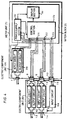
- Fig. 1 is a block diagram showing the configuration of an embodiment. Indicated by 1 is a function-integrated meter unit. A meter block 2 is mounted in the meter unit 1. Plural electronic components are classified and integrated into electronic component units 3-6. Input/output ports 7-15 are mounted in the meter unit 1 and in the electronic component units 3-6 and have a plug-in connector structure such as a connector. These input/output ports act also as attach-and-detach means.
- the meter block 2 incorporates a display portion 2a, a control portion 2b for driving and controlling the display portion 2a, and a power supply portion 2c for supplying electric power to these portions 2a, 2b.
- the display portion 2a displays the vehicle speed, the engine speed, and other information.
- the control portion 2b consists of a microcomputer.
- the power supply portion 2c is electrically connected with the vehicle battery (not shown).
- the electronic component unit 3 integrates various electronic components such as seat belt warning system, light turning-off reminding warning system, and key takeout reminding warning system.
- the unit 3 has an input circuit 3a and an output circuit 3b.
- the input circuit 3a comprises interface circuits for the ignition switch, a seat belt switch, a light switch, a door switch, and so on.
- the output circuit 3b receives electric power from the power supply portion 2c, activates a warning means such as a buzzer, and provides a desired display on the display portion 2a of the meter block 2.
- the electronic component unit 4 is an integration of electronic components forming an illuminated entry system and a defogger timer, respectively, and has an input circuit 4a and an output circuit 4b.
- the input circuit 4a is an interface circuit for a door switch, a defogger switch, or the like.
- the output circuit 4b is a driver circuit for supplying electric power from the power supply portion 2c to a light source or to a heating coil.
- the electronic component unit 5 is an integration of the electronic component unit 4 with an electronic component consisting of a power door lock.
- the component unit 5 has an input circuit 5a and an output circuit 5b.
- the input circuit 5a is an interface circuit for a door lock switch, a key cylinder switch, or the like.
- the output circuit 5b is a driver circuit receiving electric power from the power supply portion 2c and driving the door lock actuator.
- the electronic component unit 6 is an integration of the electronic component units 4, 5 with an electronic component consisting of a keyless entry system.
- the component unit 6 has an input circuit 6a that is an interface circuit for an antenna or a receiver circuit that receives a signal emitted by the driver or other person.
- a driver circuit receives electric power from the power supply portion 2c and opens and closes the door lock. Since this driver circuit acts also as the output circuit 5b, any dedicated driver circuit is not mounted.
- the electronic component unit 3 is built into the meter unit 1, since it is used for every kind of vehicle. Its input/output ports 7 are exposed from the meter unit 1.
- the three remaining electronic component units 4-6 are appropriately selected in the production lines according to the vehicular specifications for specific climatic areas or the vehicle grade, and are mounted to the meter unit 1 via the junction block 7.
- the input/output port 11 of the electronic component unit 4 is connected to the input/output port 8 of the meter unit 1 in one touch (see Fig. 2).
- input/output ports 11, 13 of the electronic component unit 5 are connected to the input/output ports 8, 9 of the meter unit 1 in one touch (see Fig.
- the control portion 2b monitors the input/output ports 8-10 of the meter unit 1 and identifies the electronic component unit mounted to the meter unit 1. Specifically, when any one of the electronic component units 4-6 is connected with the meter unit 1 via the input/output port 11, 13, or 15, the potential at the input terminals 21-23 of the control portion 2b linked to the connected input/output ports 8-10 varies from high to low level. The meter unit 1 monitors their potentials using these input terminals 21-23 as identification means. In this way, the meter unit can identify the kinds of the electronic component units 4-6 by itself.
- the identification means are not limited to the above-described input terminals 21-23. Alternatively, one may gain access to the control portion 2a of the meter block 2 from outside the meter unit 1 when or after any appropriate one of the electronic component units 4-6 is selected and mounted to the meter unit 1 in the manufacturing lines. Of course, however, designing the meter unit 1 to act as means capable of identification by itself as in the above-described embodiment considerably contributes to simplification of the manufacturing process line.
- the present invention classifies and integrates electronic components other than the meter unit into plural kinds as electronic component units.
- Attach-and-detach means are mounted to permit the electronic component units to be mounted to and detached from the meter unit.
- a control portion for controlling the electronic component units and a power supply portion for supplying electric power to the electronic component units are mounted in the meter unit.
- the electronic component units are controlled and electrically energized via the attach-and-detach means.
- Identification means permitting the meter unit to identify the kinds of the electronic component units by itself are mounted. Hence, any special operation is not necessary in the production lines. This can greatly contribute to simplification of the process steps.
- the present invention is adapted for a meter driving device having many kinds of electronic components that are used in a combination that varies according to the vehicular specifications for specific climatic areas or the vehicle grade.
- Reference Item 1 Meter unit 2 Meter block 2a Display section 2b Control section 2c Power supply section 3, 4, 5, 6 Electric component unit 3a, 4a, 5a, 6a Input circuit 3b, 4b, 5b Output circuit
Landscapes
- Engineering & Computer Science (AREA)
- Mechanical Engineering (AREA)
- Chemical & Material Sciences (AREA)
- Combustion & Propulsion (AREA)
- Transportation (AREA)
- Automation & Control Theory (AREA)
- Physics & Mathematics (AREA)
- General Physics & Mathematics (AREA)
- Instrument Panels (AREA)
- Charge And Discharge Circuits For Batteries Or The Like (AREA)
- Selective Calling Equipment (AREA)
- Electric Propulsion And Braking For Vehicles (AREA)
Applications Claiming Priority (3)
| Application Number | Priority Date | Filing Date | Title |
|---|---|---|---|
| JP8227256A JPH1070783A (ja) | 1996-08-29 | 1996-08-29 | メータ駆動装置 |
| JP227256/96 | 1996-08-29 | ||
| PCT/JP1997/002125 WO1998009137A1 (fr) | 1996-08-29 | 1997-06-19 | Element moteur de compteur |
Publications (2)
| Publication Number | Publication Date |
|---|---|
| EP0859221A1 true EP0859221A1 (de) | 1998-08-19 |
| EP0859221A4 EP0859221A4 (de) | 1999-11-17 |
Family
ID=16857978
Family Applications (1)
| Application Number | Title | Priority Date | Filing Date |
|---|---|---|---|
| EP97927402A Withdrawn EP0859221A4 (de) | 1996-08-29 | 1997-06-19 | Anordnung zur steuerung eines anzeigeinstruments |
Country Status (6)
| Country | Link |
|---|---|
| US (1) | US6177878B1 (de) |
| EP (1) | EP0859221A4 (de) |
| JP (1) | JPH1070783A (de) |
| KR (1) | KR100267803B1 (de) |
| CN (1) | CN1089892C (de) |
| WO (1) | WO1998009137A1 (de) |
Cited By (1)
| Publication number | Priority date | Publication date | Assignee | Title |
|---|---|---|---|---|
| EP1327563A1 (de) * | 2002-01-10 | 2003-07-16 | Finmek Magneti Marelli Sistemi Elettronici S.p.A. | Integrierte, elektronische Kraftfahrzeugsteuerungseinheit |
Families Citing this family (21)
| Publication number | Priority date | Publication date | Assignee | Title |
|---|---|---|---|---|
| US6963146B2 (en) * | 2001-02-07 | 2005-11-08 | Teleflex Incorporated | Modular power control apparatus |
| JP2005165587A (ja) * | 2003-12-02 | 2005-06-23 | Yazaki Corp | 車載メータシステム |
| JP5829681B2 (ja) | 2010-06-03 | 2015-12-09 | ミッドトロニクス インコーポレイテッド | 電気自動車用バッテリパックのメンテナンス |
| US11740294B2 (en) | 2010-06-03 | 2023-08-29 | Midtronics, Inc. | High use battery pack maintenance |
| US10046649B2 (en) * | 2012-06-28 | 2018-08-14 | Midtronics, Inc. | Hybrid and electric vehicle battery pack maintenance device |
| US11325479B2 (en) | 2012-06-28 | 2022-05-10 | Midtronics, Inc. | Hybrid and electric vehicle battery maintenance device |
| US10843574B2 (en) | 2013-12-12 | 2020-11-24 | Midtronics, Inc. | Calibration and programming of in-vehicle battery sensors |
| US12320857B2 (en) | 2016-10-25 | 2025-06-03 | Midtronics, Inc. | Electrical load for electronic battery tester and electronic battery tester including such electrical load |
| US11054480B2 (en) | 2016-10-25 | 2021-07-06 | Midtronics, Inc. | Electrical load for electronic battery tester and electronic battery tester including such electrical load |
| US11513160B2 (en) | 2018-11-29 | 2022-11-29 | Midtronics, Inc. | Vehicle battery maintenance device |
| US11566972B2 (en) | 2019-07-31 | 2023-01-31 | Midtronics, Inc. | Tire tread gauge using visual indicator |
| US11545839B2 (en) | 2019-11-05 | 2023-01-03 | Midtronics, Inc. | System for charging a series of connected batteries |
| US11668779B2 (en) | 2019-11-11 | 2023-06-06 | Midtronics, Inc. | Hybrid and electric vehicle battery pack maintenance device |
| US11474153B2 (en) | 2019-11-12 | 2022-10-18 | Midtronics, Inc. | Battery pack maintenance system |
| DE102020216599A1 (de) | 2019-12-31 | 2021-07-01 | Midtronics, Inc. | Intelligente Modulschnittstelle für eine Batteriewartungsvorrichtung |
| US11973202B2 (en) | 2019-12-31 | 2024-04-30 | Midtronics, Inc. | Intelligent module interface for battery maintenance device |
| US11486930B2 (en) | 2020-01-23 | 2022-11-01 | Midtronics, Inc. | Electronic battery tester with battery clamp storage holsters |
| US12517178B2 (en) | 2021-05-27 | 2026-01-06 | Midtronics, Inc. | Battery monitoring system |
| US12555965B2 (en) | 2021-08-24 | 2026-02-17 | Midtronics, Inc. | Power adapter for automotive vehicle maintenance device |
| US12330513B2 (en) | 2022-02-14 | 2025-06-17 | Midtronics, Inc. | Battery maintenance device with high voltage connector |
| US12392833B2 (en) | 2022-05-09 | 2025-08-19 | Midtronics, Inc. | Electronic battery tester |
Family Cites Families (10)
| Publication number | Priority date | Publication date | Assignee | Title |
|---|---|---|---|---|
| US4119948A (en) * | 1976-04-29 | 1978-10-10 | Ernest Michael Ward | Remote meter reading system |
| JPH0439531Y2 (de) * | 1985-05-16 | 1992-09-16 | ||
| US5154617A (en) * | 1989-05-09 | 1992-10-13 | Prince Corporation | Modular vehicle electronic system |
| JP2631903B2 (ja) | 1990-06-05 | 1997-07-16 | 喜代治 下田 | ユニットバス床部の暖房構造 |
| JPH06276571A (ja) | 1993-01-22 | 1994-09-30 | Furukawa Electric Co Ltd:The | 多重伝送装置 |
| JP2989457B2 (ja) | 1993-02-17 | 1999-12-13 | 矢崎総業株式会社 | メータモジュール |
| JP2926674B2 (ja) | 1993-03-17 | 1999-07-28 | 矢崎総業株式会社 | メータモジュールおよびその接続装置 |
| JP3135014B2 (ja) | 1993-06-03 | 2001-02-13 | 矢崎総業株式会社 | ワイヤハーネスプロテクタおよびインストルメントワイヤハーネスの接続装置 |
| JP3388850B2 (ja) | 1993-12-28 | 2003-03-24 | マツダ株式会社 | 多重伝送装置 |
| JP3585011B2 (ja) | 1996-09-24 | 2004-11-04 | 日本精機株式会社 | メータ駆動装置 |
-
1996
- 1996-08-29 JP JP8227256A patent/JPH1070783A/ja active Pending
-
1997
- 1997-06-19 CN CN97191138A patent/CN1089892C/zh not_active Expired - Fee Related
- 1997-06-19 KR KR1019980703239A patent/KR100267803B1/ko not_active Expired - Fee Related
- 1997-06-19 US US09/068,004 patent/US6177878B1/en not_active Expired - Fee Related
- 1997-06-19 EP EP97927402A patent/EP0859221A4/de not_active Withdrawn
- 1997-06-19 WO PCT/JP1997/002125 patent/WO1998009137A1/ja not_active Ceased
Cited By (1)
| Publication number | Priority date | Publication date | Assignee | Title |
|---|---|---|---|---|
| EP1327563A1 (de) * | 2002-01-10 | 2003-07-16 | Finmek Magneti Marelli Sistemi Elettronici S.p.A. | Integrierte, elektronische Kraftfahrzeugsteuerungseinheit |
Also Published As
| Publication number | Publication date |
|---|---|
| CN1199460A (zh) | 1998-11-18 |
| KR19990067269A (ko) | 1999-08-16 |
| US6177878B1 (en) | 2001-01-23 |
| CN1089892C (zh) | 2002-08-28 |
| EP0859221A4 (de) | 1999-11-17 |
| JPH1070783A (ja) | 1998-03-10 |
| WO1998009137A1 (fr) | 1998-03-05 |
| KR100267803B1 (ko) | 2000-10-16 |
Similar Documents
| Publication | Publication Date | Title |
|---|---|---|
| US6177878B1 (en) | Meter driving device | |
| DE69917821T2 (de) | Rückspiegelanordnung mit Fahrzeug- Informationsanzeige | |
| DE60019939T2 (de) | Umrüstbare modulare instrumentenkonsole | |
| US6181563B1 (en) | Meter device for vehicle | |
| US20020140292A1 (en) | Wake up system for electronic component supported on a vehicle | |
| EP0796178A1 (de) | Schaltungsanordnung für in einem kraftfahrzeug anordbare funktionsmodule | |
| EP0491095B1 (de) | Einleiter-Kraftfahrzeug-Multiplex-Anlage, die zufällig reflektierte Infrarote Wellen benutzt | |
| US6206130B1 (en) | Vehicle anti-theft device | |
| KR100348839B1 (ko) | 차량용전원공급장치 | |
| EP0871015A1 (de) | Anordnung zur steuerung eines anzeigeinstruments | |
| EP0917991A2 (de) | Kraftfahrzeugmultiplex - Übertragungssystem und Herstellungsverfahren | |
| EP0751454A2 (de) | System zum Entwerfen von Steuerungsvorgaben für Vorrichtungen zum Steuern von Lasten | |
| US6211578B1 (en) | Instrumentation for vehicles | |
| JP3257685B2 (ja) | 電源分配システム | |
| JPH06276571A (ja) | 多重伝送装置 | |
| US6906613B1 (en) | Keyless entry system | |
| JPH05146080A (ja) | 車載用電源分配システム | |
| DE212018000369U1 (de) | System zur Identifizierung eines Fahrzeugbetriebsmodus | |
| WO2003067411A1 (en) | Function panel | |
| EP4414217B1 (de) | Fahrzeuglampe, steuerungsvorrichtung und steuerungsverfahren für fahrzeuglampe | |
| EP1327563A1 (de) | Integrierte, elektronische Kraftfahrzeugsteuerungseinheit | |
| RU2205118C2 (ru) | Система безопасности автомобиля | |
| DE102024204445A1 (de) | Fahrzeugseitige intelligente steuervorrichtung | |
| GB2328566A (en) | Controlling courtesy light of a taxi |
Legal Events
| Date | Code | Title | Description |
|---|---|---|---|
| PUAI | Public reference made under article 153(3) epc to a published international application that has entered the european phase |
Free format text: ORIGINAL CODE: 0009012 |
|
| 17P | Request for examination filed |
Effective date: 19980526 |
|
| AK | Designated contracting states |
Kind code of ref document: A1 Designated state(s): DE FR GB IT NL SE |
|
| A4 | Supplementary search report drawn up and despatched |
Effective date: 19991006 |
|
| AK | Designated contracting states |
Kind code of ref document: A4 Designated state(s): DE FR GB IT NL SE |
|
| STAA | Information on the status of an ep patent application or granted ep patent |
Free format text: STATUS: THE APPLICATION HAS BEEN WITHDRAWN |
|
| 18W | Application withdrawn |
Withdrawal date: 20020410 |