EP0859478A2 - Drahlose Übertragungssysteme mit im freien Raum optischen Übertragungsstrecken - Google Patents
Drahlose Übertragungssysteme mit im freien Raum optischen Übertragungsstrecken Download PDFInfo
- Publication number
- EP0859478A2 EP0859478A2 EP97306230A EP97306230A EP0859478A2 EP 0859478 A2 EP0859478 A2 EP 0859478A2 EP 97306230 A EP97306230 A EP 97306230A EP 97306230 A EP97306230 A EP 97306230A EP 0859478 A2 EP0859478 A2 EP 0859478A2
- Authority
- EP
- European Patent Office
- Prior art keywords
- optical
- light
- communicating
- remote
- information
- Prior art date
- Legal status (The legal status is an assumption and is not a legal conclusion. Google has not performed a legal analysis and makes no representation as to the accuracy of the status listed.)
- Granted
Links
Images


Classifications
-
- H—ELECTRICITY
- H04—ELECTRIC COMMUNICATION TECHNIQUE
- H04B—TRANSMISSION
- H04B10/00—Transmission systems employing electromagnetic waves other than radio-waves, e.g. infrared, visible or ultraviolet light, or employing corpuscular radiation, e.g. quantum communication
- H04B10/25—Arrangements specific to fibre transmission
- H04B10/2575—Radio-over-fibre, e.g. radio frequency signal modulated onto an optical carrier
- H04B10/25752—Optical arrangements for wireless networks
-
- H—ELECTRICITY
- H04—ELECTRIC COMMUNICATION TECHNIQUE
- H04B—TRANSMISSION
- H04B10/00—Transmission systems employing electromagnetic waves other than radio-waves, e.g. infrared, visible or ultraviolet light, or employing corpuscular radiation, e.g. quantum communication
- H04B10/07—Arrangements for monitoring or testing transmission systems; Arrangements for fault measurement of transmission systems
- H04B10/075—Arrangements for monitoring or testing transmission systems; Arrangements for fault measurement of transmission systems using an in-service signal
- H04B10/077—Arrangements for monitoring or testing transmission systems; Arrangements for fault measurement of transmission systems using an in-service signal using a supervisory or additional signal
- H04B10/0773—Network aspects, e.g. central monitoring of transmission parameters
-
- H—ELECTRICITY
- H04—ELECTRIC COMMUNICATION TECHNIQUE
- H04B—TRANSMISSION
- H04B10/00—Transmission systems employing electromagnetic waves other than radio-waves, e.g. infrared, visible or ultraviolet light, or employing corpuscular radiation, e.g. quantum communication
- H04B10/11—Arrangements specific to free-space transmission, i.e. transmission through air or vacuum
- H04B10/112—Line-of-sight transmission over an extended range
- H04B10/1123—Bidirectional transmission
- H04B10/1125—Bidirectional transmission using a single common optical path
-
- H—ELECTRICITY
- H04—ELECTRIC COMMUNICATION TECHNIQUE
- H04B—TRANSMISSION
- H04B2210/00—Indexing scheme relating to optical transmission systems
- H04B2210/07—Monitoring an optical transmission system using a supervisory signal
- H04B2210/078—Monitoring an optical transmission system using a supervisory signal using a separate wavelength
Definitions
- This invention relates to wireless communications systems such as cellular telephone systems, and more particularly to wireless communications systems with increased communication capacity.
- Wireless communications systems such as cellular telephone systems rely on a relatively small number of radio frequencies that are broadcast from relatively low-power transceivers so that the signals travel only a relatively short distance from the transceiver (e.g., approximately to the boundary of a cell having a radius of one to three miles from the transceiver).
- the same radio frequencies can therefore be reused for other messages in nearby cells without unacceptable interference between the different messages on the same frequencies in different cells.
- the number of radio frequencies allowed for this type of communication is limited by governmental regulation and other considerations, only a correspondingly limited number of cellular telephone calls can be supported in any given cell at any one time. In high usage areas this may prevent some calls from being completed and/or may force some callers to wait for service. This is obviously undesirable.
- a conventional cell may be subdivided into a plurality of subcells, each having a transceiver of even lower power than the conventional transceiver associated with a conventional cell. If a conventional cell is subdivided into four subcells, it is theoretically possible to support four times as many calls in the area of the original cell as could be supported if the cell were not subdivided.
- a possible disincentive to subdividing cells is the expense of running high-grade, hard-wired communications links such as optical fiber to all the new subcell transceiver locations.
- a central location in a wireless communications system cell may be the location of the pre-existing radio frequency transceiver of the cell.
- This transceiver is converted to a plurality of central optical transceivers.
- Each of the subcells is provided with an optical transceiver that is centrally located within the associated subcell and therefore remote from the previously mentioned central optical transceivers.
- Each subcell optical transceiver is optically coupled to a respective one of the central optical transceivers by a substantially unguided, free-space, optical communications link (e.g., bi-directional, line-of-sight, infrared transmission).
- Each subcell also includes a radio frequency transceiver for serving wireless communications units (e.g., mobile or cellular telephones) in that subcell.
- each subcell includes circuitry for interfacing between its optical and radio frequency transceivers.
- the central optical transceivers typically communicate with portions of the overall system beyond the cell via a hard-wired communications link (e.g., a bi-directional fiber optic link to a mobile telephone switching office).
- FIG. 1 is a simplified schematic diagram of a representative portion of an illustrative embodiment of a wireless communications system constructed in accordance with this invention.
- FIG. 2 is a simplified schematic diagram of an illustrative embodiment of a portion of the apparatus shown in FIG. 1.
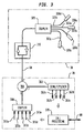
- FIG. 3 is a more detailed, but still simplified schematic block diagram of an illustrative embodiment of another portion of the apparatus shown in FIG. 1.
- chain-dotted line 20 represents the approximate boundary of a conventional cell in wireless communications system 10.
- cell 20 may be approximately circular with a radius in the range from about one to three miles from a central antenna 30.
- cell 20 is subdivided into a plurality of subcells 40a-d. Each of subcells 40a-d is served by a respective antenna 50a-d.
- the apparatus at antenna 30 communicates with switching equipment 70 (e.g., a mobile telephone switching office) via hard-wired communications link 60.
- Link 60 is preferably optical fiber, but it can alternatively be an electronic link.
- Cell 20 is only representative of several similar cells that may be similarly served by switching office 70.
- Switching office 70 is connected to conventional telephone company switching equipment 90 via communications link 80 for communication with the global communications network generally. If desired, components 70 and 90 may be at the same physical location.
- communications system 10 is a cellular telephone system
- the invention is equally applicable to any type of wireless communications system (e.g., paging systems, cellular telephone systems with enhanced features, and the like).
- the apparatus at antenna 30 communicates with the apparatus at each of antennas 50a-d via substantially unguided optical communication between the antennas.
- antenna 30 has light sources for sending light 32a-d through the atmosphere to each of antennas 50a-d.
- Each antenna 50a-d receives the light thus transmitted to it from antenna 30 and broadcasts radio frequency signals within the associated subcell 40a-d corresponding to the information received optically (or an appropriate part of that information).
- Cellular telephones that are in use within a subcell 40a-d receive this radio frequency information and use other, dynamically assigned radio frequencies to send other information back to the associated antenna 50a-d.
- substantially unguided, free-space, optical links 32a-d and 52a-d between antenna 30, on the one hand, and antennas 50a-d, on the other hand facilitates subdividing cell 20 into subcells 40a-40d without the expense of having to provide hard-wired connections like link 60 from switching office 70 to all of antennas 50a-d.
- a pre-existing link 60 between switching office 70 and a formerly radio-frequency transceiver 30 can be reused in this system.
- Transceiver 30 is converted from a radio frequency transceiver to a plurality of optical transceivers for optical communication with transceivers 50a-d. No additional hard-wired connections are needed between switching office 70 and transceivers 50a-d.
- FIG. 2 An illustrative embodiment of the optical portion of representative subcell apparatus 50 in accordance with this invention is shown in FIG. 2.
- incoming light 32 includes five different wavelength-division-multiplexed light wavelengths. Four of these wavelengths are respectively the message information signals for the four subcells 40a-d served by antenna 30.
- the fifth wavelength is a control information signal shared by all of the subcells 40a-d served by antenna 30. For example, this control information may determine the radio frequencies used by the apparatus at each of remote antennas 50a-d for communication with the cellular telephones being served from that remote antenna.
- Collimating lens 110 focuses incoming light 32 into optical fiber 120 leading to port 2 of forward propagating optical circulator 130.
- forward propagating optical circulator 130 propagates optical information from port 1 to port 2, and from port 2 to port 3, but not from port 3 to port 1. (This characteristic is extendable to any number of ports.)
- optical circulator 130 applies the incoming light from port 2 to the optical fiber 140 connected to its port 3.
- Circulator 160 applies the light it receives via port 1 to the optical fiber 170 which is connected to its port 2.
- Optical fiber 170 includes Bragg grating filter 180 for blocking further propagation along that fiber of the control signal wavelength.
- Photodetector 190 is the message information signal input to the electronic circuitry 200 of subcell apparatus 50.
- Bragg grating 180 reflects the control signal wavelength back to port 2 of optical circulator 160. Accordingly, circulator 160 applies the control signal wavelength from port 2 to the optical fiber 210 connected to its port 3.
- Optical fiber 210 is optically coupled to photodetector 220, which is the control signal input to electronic circuitry 200.
- Radio frequency signals received by subcell apparatus 50 from cellular telephones in the associated subcell are processed by the electronic circuitry in the substantially conventional way and applied as a modulating signal to light source 230.
- Light from light source 230 is optically coupled to optical fiber 240, which is connected to port 1 of optical circulator 130. Accordingly, light from port 1 of circulator 130 is applied to optical fiber 120 and passed out through collimating lens 110 for transmission back to transceiver 30 as substantially unguided light 52.
- the wavelength of light source 230 is preferably different from any of incoming wavelengths 32.
- Each of the subcells 40 in a cell 20 also preferably has its own unique light source 230 wavelength.
- FIG. 3 shows an illustrative embodiment of elements 30, 60, and 70 in more detail.
- a plurality of free-space optical transceivers 330a-d are respectively aimed at subcell antennas 50a-d.
- Each of transceivers 330a-d transmits the light it receives from mobile telephone switching office 70 via optical fiber 60 to the associated subcell antenna 50a-d. As described earlier, this transmission from antenna 30 to antennas 50a-d is free-space optical transmission 32a-d. All of transceivers 330a-d may transmit substantially the same information.
- This information includes a separate message information wavelength for each of subcells 40a-d, and a further separate control information wavelength carrying information for controlling all of subcells 40a-d.
- Each subcell apparatus filters out the message information wavelength intended for it, as well as the control information wavelength, as described above in connection with FIG. 2.
- Coupler 320 distributes the light coming in from optical fiber 60 to the optical fibers 322a-d leading to transceivers 330a-d. In the opposite direction, coupler 320 combines the light received back from subcell antennas 50a-b for application to optical fiber 60.
- Optical fiber 60 may include a conventional erbium doped fiber amplifier 310 for optically amplifying the light passing in either or both directions along the optical fiber.
- Call processing circuitry 370 also produces electronic signals for transmission to each of subcells 40a-d. Each of these electronic signals is converted to a respective optical signal 372a-e having a separate wavelength. Signals 372a-d are respectively the message information signals for subcells 40a-d, while signal 372e is the control information signal for all of subcells 40a-d. Coupler 380 combines these five optical signals into a wavelength division multiplexed optical signal which is applied to port 1 of optical circulator 350. Circulator 350 transmits this signal from port 1 to port 2, where it is applied to optical fiber 60 for transmission to central antenna 30.
- the information for all subcells could be transmitted on one wavelength, with each subcell including apparatus for electronically extracting the information intended for that subcell. This would somewhat simplify the optical processing apparatus for light being transmitted to and processed by the subcells, but it would increase the complexity of the electronic circuitry 200 required at each subcell.
Landscapes
- Physics & Mathematics (AREA)
- Electromagnetism (AREA)
- Engineering & Computer Science (AREA)
- Computer Networks & Wireless Communication (AREA)
- Signal Processing (AREA)
- Optical Communication System (AREA)
- Mobile Radio Communication Systems (AREA)
Applications Claiming Priority (2)
| Application Number | Priority Date | Filing Date | Title |
|---|---|---|---|
| US799885 | 1997-02-13 | ||
| US08/799,885 US5844705A (en) | 1997-02-13 | 1997-02-13 | Wireless communications systems employing free-space optical communications links |
Publications (3)
| Publication Number | Publication Date |
|---|---|
| EP0859478A2 true EP0859478A2 (de) | 1998-08-19 |
| EP0859478A3 EP0859478A3 (de) | 1999-07-28 |
| EP0859478B1 EP0859478B1 (de) | 2001-07-18 |
Family
ID=25177015
Family Applications (1)
| Application Number | Title | Priority Date | Filing Date |
|---|---|---|---|
| EP97306230A Expired - Lifetime EP0859478B1 (de) | 1997-02-13 | 1997-08-15 | Drahlose Übertragungssysteme mit im freien Raum optischen Übertragungsstrecken |
Country Status (6)
| Country | Link |
|---|---|
| US (1) | US5844705A (de) |
| EP (1) | EP0859478B1 (de) |
| JP (1) | JP3757050B2 (de) |
| CN (1) | CN1190828A (de) |
| CA (1) | CA2212556C (de) |
| DE (1) | DE69705698T2 (de) |
Cited By (7)
| Publication number | Priority date | Publication date | Assignee | Title |
|---|---|---|---|---|
| WO1999045665A1 (en) * | 1998-03-05 | 1999-09-10 | Air Fiber, Inc. | Hybrid picocell communication system |
| WO2000025455A1 (en) * | 1998-10-27 | 2000-05-04 | Airfiber, Inc. | Wireless communication network with free space optical connection between nodes |
| EP1231724A1 (de) * | 2001-02-03 | 2002-08-14 | Alcatel | Verfahren zur Übertragung eines optischen Signals durch den freien Raum |
| WO2002039615A3 (en) * | 2000-11-09 | 2002-10-10 | Celerica Inc | Cellular base station with remote antenna |
| US6624916B1 (en) | 1997-02-11 | 2003-09-23 | Quantumbeam Limited | Signalling system |
| EP1233551A3 (de) * | 2001-02-15 | 2004-02-18 | NTT DoCoMo, Inc. | Verfahren und Vorrichtung zum optischen Senden/Empfängen und optisches Kommunikationsnetzwerk |
| US7136585B2 (en) | 2001-12-14 | 2006-11-14 | Kiribati Wireless Ventures, Llc | Optical amplifiers in a free space laser communication system |
Families Citing this family (22)
| Publication number | Priority date | Publication date | Assignee | Title |
|---|---|---|---|---|
| US6348986B1 (en) * | 1996-03-29 | 2002-02-19 | Dominion Lasercom. Inc. | Wireless fiber-coupled telecommunication systems based on atmospheric transmission of laser signals |
| KR100259843B1 (ko) * | 1997-08-14 | 2000-06-15 | 윤종용 | 고출력 증폭기와 광 안테나의 정합 시스템을 이용한 양방향성 옥외용 기지국 |
| US6239888B1 (en) * | 1998-04-24 | 2001-05-29 | Lightpointe Communications, Inc. | Terrestrial optical communication network of integrated fiber and free-space links which requires no electro-optical conversion between links |
| US6868237B2 (en) * | 1998-04-24 | 2005-03-15 | Lightpointe Communications, Inc. | Terrestrial optical communication network of integrated fiber and free-space links which requires no electro-optical conversion between links |
| BR9912826A (pt) * | 1998-07-16 | 2001-05-02 | Terabeam Networks Inc | Sistema ótico de comunicação que transmite e recebe dados através de espaço livre |
| US6763195B1 (en) | 2000-01-13 | 2004-07-13 | Lightpointe Communications, Inc. | Hybrid wireless optical and radio frequency communication link |
| US6788898B1 (en) * | 2000-04-14 | 2004-09-07 | At&T Corp. | Optical/radio local access network |
| US7095957B1 (en) | 2000-08-17 | 2006-08-22 | At&T Corp. | Optical/radio local access network |
| JP2002246965A (ja) * | 2001-02-15 | 2002-08-30 | Ntt Docomo Inc | 情報伝送方法及びシステム、並びに送信装置、及び受信装置 |
| US20020131130A1 (en) * | 2001-03-09 | 2002-09-19 | Lightpointe Communications, Inc. | Multi-tenant unit optical network |
| WO2002073845A2 (en) * | 2001-03-09 | 2002-09-19 | Lightpointe Communications, Inc. | Free space optical communication network |
| US6889009B2 (en) * | 2001-04-16 | 2005-05-03 | Lightpointe Communications, Inc. | Integrated environmental control and management system for free-space optical communication systems |
| US6826164B2 (en) * | 2001-06-08 | 2004-11-30 | Nextg Networks | Method and apparatus for multiplexing in a wireless communication infrastructure |
| US7127175B2 (en) * | 2001-06-08 | 2006-10-24 | Nextg Networks | Method and apparatus for multiplexing in a wireless communication infrastructure |
| SE523400C2 (sv) * | 2001-11-30 | 2004-04-13 | Ericsson Telefon Ab L M | Cellulärt radiokommunikationssystem som utnyttjar trådlösa optiska länkar samt förfarande för drift av systemet |
| US20040109831A1 (en) * | 2002-07-18 | 2004-06-10 | M & M Inx Co. | Cosmetic compositions for the protection and optical enhancement of tattooed skin |
| US20040082365A1 (en) * | 2002-07-18 | 2004-04-29 | Celerica Ltd | Digitization and transmitting cellular RF signals by several light wavelengths |
| US20040198453A1 (en) * | 2002-09-20 | 2004-10-07 | David Cutrer | Distributed wireless network employing utility poles and optical signal distribution |
| CN100455104C (zh) * | 2004-11-08 | 2009-01-21 | 中兴通讯股份有限公司 | 光学信道与无线电信道间的切换方法 |
| US7848517B2 (en) | 2005-03-16 | 2010-12-07 | At&T Intellectual Property Ii, L.P. | Secure open-air communication system utilizing multi-channel decoyed transmission |
| TWI385958B (zh) * | 2009-03-20 | 2013-02-11 | Ind Tech Res Inst | 支援無線通訊之被動光網路系統 |
| CN112291001A (zh) * | 2020-10-23 | 2021-01-29 | 军事科学院系统工程研究院网络信息研究所 | 电光双载波互校验自由空间通信方法 |
Family Cites Families (5)
| Publication number | Priority date | Publication date | Assignee | Title |
|---|---|---|---|---|
| CA2008900C (en) * | 1989-04-04 | 1998-01-20 | Ta-Shing Chu | Optical fiber microcellular mobile radio |
| US5067173A (en) * | 1990-12-20 | 1991-11-19 | At&T Bell Laboratories | Microcellular communications system using space diversity reception |
| JPH0530044A (ja) * | 1991-07-25 | 1993-02-05 | Kokusai Denshin Denwa Co Ltd <Kdd> | 光通信方式 |
| MX9206570A (es) * | 1991-11-15 | 1993-07-01 | Csir | Red de telecomunicaciones y metodo para establecer dicha red de telecomunicaciones. |
| WO1993012596A1 (en) * | 1991-12-16 | 1993-06-24 | Motorola, Inc. | Optical distribution system |
-
1997
- 1997-02-13 US US08/799,885 patent/US5844705A/en not_active Expired - Lifetime
- 1997-08-07 CA CA002212556A patent/CA2212556C/en not_active Expired - Fee Related
- 1997-08-15 EP EP97306230A patent/EP0859478B1/de not_active Expired - Lifetime
- 1997-08-15 DE DE69705698T patent/DE69705698T2/de not_active Expired - Lifetime
-
1998
- 1998-02-11 CN CN98103823A patent/CN1190828A/zh active Pending
- 1998-02-13 JP JP03072298A patent/JP3757050B2/ja not_active Expired - Fee Related
Cited By (10)
| Publication number | Priority date | Publication date | Assignee | Title |
|---|---|---|---|---|
| US6624916B1 (en) | 1997-02-11 | 2003-09-23 | Quantumbeam Limited | Signalling system |
| WO1999045665A1 (en) * | 1998-03-05 | 1999-09-10 | Air Fiber, Inc. | Hybrid picocell communication system |
| US6323980B1 (en) | 1998-03-05 | 2001-11-27 | Air Fiber, Inc. | Hybrid picocell communication system |
| AU749110B2 (en) * | 1998-03-05 | 2002-06-20 | Air Fiber, Inc. | Hybrid picocell communication system |
| WO2000025455A1 (en) * | 1998-10-27 | 2000-05-04 | Airfiber, Inc. | Wireless communication network with free space optical connection between nodes |
| WO2002039615A3 (en) * | 2000-11-09 | 2002-10-10 | Celerica Inc | Cellular base station with remote antenna |
| EP1231724A1 (de) * | 2001-02-03 | 2002-08-14 | Alcatel | Verfahren zur Übertragung eines optischen Signals durch den freien Raum |
| EP1233551A3 (de) * | 2001-02-15 | 2004-02-18 | NTT DoCoMo, Inc. | Verfahren und Vorrichtung zum optischen Senden/Empfängen und optisches Kommunikationsnetzwerk |
| US7136585B2 (en) | 2001-12-14 | 2006-11-14 | Kiribati Wireless Ventures, Llc | Optical amplifiers in a free space laser communication system |
| US7761009B2 (en) | 2001-12-14 | 2010-07-20 | Scott Harris Bloom | Optical amplifiers in a free space laser communication system |
Also Published As
| Publication number | Publication date |
|---|---|
| CN1190828A (zh) | 1998-08-19 |
| DE69705698T2 (de) | 2002-06-13 |
| EP0859478B1 (de) | 2001-07-18 |
| CA2212556A1 (en) | 1998-08-13 |
| CA2212556C (en) | 2001-05-01 |
| JPH10233740A (ja) | 1998-09-02 |
| JP3757050B2 (ja) | 2006-03-22 |
| DE69705698D1 (de) | 2001-08-23 |
| MX9801084A (es) | 1998-08-30 |
| US5844705A (en) | 1998-12-01 |
| EP0859478A3 (de) | 1999-07-28 |
Similar Documents
| Publication | Publication Date | Title |
|---|---|---|
| US5844705A (en) | Wireless communications systems employing free-space optical communications links | |
| JP3115644B2 (ja) | 無線通信システム、特にセル車両無線システム | |
| EP0476569B1 (de) | Mobiles Kommunikationssystem | |
| US10122446B2 (en) | Optical/radio local access network | |
| JP2956981B2 (ja) | 通信システム | |
| KR101135935B1 (ko) | 분산 디지털 안테나 시스템 | |
| JP3169665B2 (ja) | 光増幅器を備えた加入者区域用光通信システム | |
| US5838474A (en) | Process and circuit arrangement for transmitting received signals from an antenna to a base station of a radio system | |
| EP1438797B1 (de) | Integration eines faseroptischen festzugriffs- und eines faseroptischen funkzugriffsnetzwerks | |
| RU2048703C1 (ru) | Двунаправленная световодная система телесвязи | |
| US6788898B1 (en) | Optical/radio local access network | |
| US7295777B1 (en) | Optical/radio local access network | |
| JPH04213230A (ja) | セル状車両無線システム | |
| WO1986005649A1 (en) | Optical networks | |
| JPH0448832A (ja) | 光リンク無線通信方式 | |
| JPH08288911A (ja) | 光通信装置およびその方法 | |
| KR100404518B1 (ko) | 4파장 애드/드롭형 파장분할 다중화기를 이용한 광통신시스템 | |
| JP3007494B2 (ja) | 移動通信の基地局装置 | |
| MXPA98001084A (en) | Wireless communications systems that use optical space communications links | |
| JPH01130638A (ja) | 周波数多重光双方向伝送装置 | |
| RU2850181C1 (ru) | Система расширения зоны обслуживания сетей радиосвязи | |
| KR20010065411A (ko) | 광트랜스폰더를 이용한 일렬형 중계 시스템 | |
| KR20010027961A (ko) | 파장 분할 다중화기와 박막 필터를 이용한 광 중계 시스템 | |
| WO2002015439A1 (en) | Communication system with fiber optical link | |
| JPH0435234A (ja) | 光ファイバー無線通信方式 |
Legal Events
| Date | Code | Title | Description |
|---|---|---|---|
| PUAI | Public reference made under article 153(3) epc to a published international application that has entered the european phase |
Free format text: ORIGINAL CODE: 0009012 |
|
| 17P | Request for examination filed |
Effective date: 19970919 |
|
| AK | Designated contracting states |
Kind code of ref document: A2 Designated state(s): DE FR GB |
|
| AX | Request for extension of the european patent |
Free format text: AL;LT;LV;RO;SI |
|
| PUAL | Search report despatched |
Free format text: ORIGINAL CODE: 0009013 |
|
| AK | Designated contracting states |
Kind code of ref document: A3 Designated state(s): AT BE CH DE DK ES FI FR GB GR IE IT LI LU MC NL PT SE |
|
| AX | Request for extension of the european patent |
Free format text: AL;LT;LV;RO;SI |
|
| RIC1 | Information provided on ipc code assigned before grant |
Free format text: 6H 04B 10/10 A, 6H 04Q 7/30 B |
|
| AKX | Designation fees paid |
Free format text: DE FR GB |
|
| 17Q | First examination report despatched |
Effective date: 20000405 |
|
| GRAG | Despatch of communication of intention to grant |
Free format text: ORIGINAL CODE: EPIDOS AGRA |
|
| GRAG | Despatch of communication of intention to grant |
Free format text: ORIGINAL CODE: EPIDOS AGRA |
|
| GRAH | Despatch of communication of intention to grant a patent |
Free format text: ORIGINAL CODE: EPIDOS IGRA |
|
| GRAH | Despatch of communication of intention to grant a patent |
Free format text: ORIGINAL CODE: EPIDOS IGRA |
|
| GRAA | (expected) grant |
Free format text: ORIGINAL CODE: 0009210 |
|
| AK | Designated contracting states |
Kind code of ref document: B1 Designated state(s): DE FR GB |
|
| REF | Corresponds to: |
Ref document number: 69705698 Country of ref document: DE Date of ref document: 20010823 |
|
| ET | Fr: translation filed | ||
| REG | Reference to a national code |
Ref country code: GB Ref legal event code: IF02 |
|
| PLBE | No opposition filed within time limit |
Free format text: ORIGINAL CODE: 0009261 |
|
| STAA | Information on the status of an ep patent application or granted ep patent |
Free format text: STATUS: NO OPPOSITION FILED WITHIN TIME LIMIT |
|
| 26N | No opposition filed | ||
| PGFP | Annual fee paid to national office [announced via postgrant information from national office to epo] |
Ref country code: DE Payment date: 20090831 Year of fee payment: 13 |
|
| PGFP | Annual fee paid to national office [announced via postgrant information from national office to epo] |
Ref country code: FR Payment date: 20100819 Year of fee payment: 14 |
|
| PGFP | Annual fee paid to national office [announced via postgrant information from national office to epo] |
Ref country code: GB Payment date: 20100708 Year of fee payment: 14 |
|
| REG | Reference to a national code |
Ref country code: DE Ref legal event code: R119 Ref document number: 69705698 Country of ref document: DE Effective date: 20110301 |
|
| PG25 | Lapsed in a contracting state [announced via postgrant information from national office to epo] |
Ref country code: DE Free format text: LAPSE BECAUSE OF NON-PAYMENT OF DUE FEES Effective date: 20110301 |
|
| GBPC | Gb: european patent ceased through non-payment of renewal fee |
Effective date: 20110815 |
|
| REG | Reference to a national code |
Ref country code: FR Ref legal event code: ST Effective date: 20120430 |
|
| PG25 | Lapsed in a contracting state [announced via postgrant information from national office to epo] |
Ref country code: GB Free format text: LAPSE BECAUSE OF NON-PAYMENT OF DUE FEES Effective date: 20110815 Ref country code: FR Free format text: LAPSE BECAUSE OF NON-PAYMENT OF DUE FEES Effective date: 20110831 |