EP0860247A1 - Rasoir électrique - Google Patents
Rasoir électrique Download PDFInfo
- Publication number
- EP0860247A1 EP0860247A1 EP98300330A EP98300330A EP0860247A1 EP 0860247 A1 EP0860247 A1 EP 0860247A1 EP 98300330 A EP98300330 A EP 98300330A EP 98300330 A EP98300330 A EP 98300330A EP 0860247 A1 EP0860247 A1 EP 0860247A1
- Authority
- EP
- European Patent Office
- Prior art keywords
- cutting member
- gear
- rotated
- outer cutting
- shaver
- Prior art date
- Legal status (The legal status is an assumption and is not a legal conclusion. Google has not performed a legal analysis and makes no representation as to the accuracy of the status listed.)
- Granted
Links
- 230000005540 biological transmission Effects 0.000 claims description 51
- 230000033001 locomotion Effects 0.000 claims description 5
- 230000008878 coupling Effects 0.000 description 4
- 238000010168 coupling process Methods 0.000 description 4
- 238000005859 coupling reaction Methods 0.000 description 4
- 230000000694 effects Effects 0.000 description 4
- 230000004048 modification Effects 0.000 description 2
- 238000012986 modification Methods 0.000 description 2
- 238000010008 shearing Methods 0.000 description 2
- 206010049565 Muscle fatigue Diseases 0.000 description 1
- 230000000994 depressogenic effect Effects 0.000 description 1
- 230000001815 facial effect Effects 0.000 description 1
- 239000002184 metal Substances 0.000 description 1
Images




Classifications
-
- B—PERFORMING OPERATIONS; TRANSPORTING
- B26—HAND CUTTING TOOLS; CUTTING; SEVERING
- B26B—HAND-HELD CUTTING TOOLS NOT OTHERWISE PROVIDED FOR
- B26B19/00—Clippers or shavers operating with a plurality of cutting edges, e.g. hair clippers, dry shavers
- B26B19/14—Clippers or shavers operating with a plurality of cutting edges, e.g. hair clippers, dry shavers of the rotary-cutter type; Cutting heads therefor; Cutters therefor
- B26B19/145—Cutters being movable in the cutting head
-
- B—PERFORMING OPERATIONS; TRANSPORTING
- B26—HAND CUTTING TOOLS; CUTTING; SEVERING
- B26B—HAND-HELD CUTTING TOOLS NOT OTHERWISE PROVIDED FOR
- B26B19/00—Clippers or shavers operating with a plurality of cutting edges, e.g. hair clippers, dry shavers
- B26B19/14—Clippers or shavers operating with a plurality of cutting edges, e.g. hair clippers, dry shavers of the rotary-cutter type; Cutting heads therefor; Cutters therefor
-
- B—PERFORMING OPERATIONS; TRANSPORTING
- B26—HAND CUTTING TOOLS; CUTTING; SEVERING
- B26B—HAND-HELD CUTTING TOOLS NOT OTHERWISE PROVIDED FOR
- B26B19/00—Clippers or shavers operating with a plurality of cutting edges, e.g. hair clippers, dry shavers
- B26B19/28—Drive layout for hair clippers or dry shavers, e.g. providing for electromotive drive
Definitions
- the present invention relates to an electric shaver and more particularly to an electric rotary shaver.
- the outer cutter which ordinarily has radial slits for introducing facial hair is not rotated as described above, the hair does not enter into the slits easily, resulting in that shaving is occasionally not performed efficiently. So as to execute a smooth and efficient shave, it is common to move the shaving head (and therefore the outer cutters) circularly on, for example, the face, which sometimes causes muscle fatigue in the arm that holds the shaver; and therefore, such a prior art shaver has a problem with the shaving effect and with the use thereof.
- the primary aim of certain embodiments of the present invention is to provide an electric shaver that can reduce the necessity of circular movements of the shaver in use, thus ensuring an easy, quick and smooth shave.
- an electric shaver which includes a rotatable outer cutter(s) which can function as a "comb” so as to smoothly raise and bring the hair into the slits formed on the outer cutter(s) and further between the outer cutter(s) and inner cutter(s), thus ensuring a smooth and quick shave.
- an electric rotary shaver which includes at least one shaving unit that comprises an outer cutter (outer cutting member) and an inner cutter (inner cutting member) so that not only is the inner cutter rotated but also the outer cutter is rotated via a series of gears provided between a single rotary power or drive source and the shaving unit(s).
- the outer cutter(s) may be provided with a ring gear(s) on, for example, its circumferential surface(s), and this ring gear(s) may be meshed with a gear(s) rotated by a transmission gear(s) which is rotated by a drive gear(s) that causes the corresponding inner cutter(s) to rotate.
- the outer cutter(s) and the inner cutter(s) are rotatable not only in the same directions but also in the opposite directions.
- Figure 1 shows the inside of the shaver according to the first embodiment of the present invention
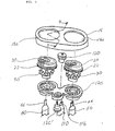
- Figure 2 is an exploded perspective view showing the important portion thereof
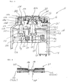
- Figure 3 shows the cross section thereof.
- the electric shaver is generally referred to by the reference numeral 10, and it includes a shaver housing 12 and two shaving units each substantially comprising an outer cutting member 20 and an inner cutting member 30.
- the tip end of the inner cutting member 30 is in contact with an inner surface of a circular top end wall of the outer cutting member 20.
- the shaver housing 12 is opened at one end and a removable head frame 16 covers this open end; and the shaver housing 12 is provided therein with a mounting plate 12a and a drive shaft holder 12b.
- a cutting member retaining frame 12c is detachably mounted to the undersurface of the head frame 16 by way of a fixing screw 12c'.
- a single electric motor 14 that is actuated by an AC and/or DC power source, a battery 18 which actuates the motor 14, and an ON-OFF switch 19 which connects the motor 14 and battery 18 are provided in the shaver housing 12.
- the head frame 16 is provided so as to be elastically snap-fitted to the shaver housing 12 in a removable fashion; and each of two outer cutting members 20 is fitted in each of two circular apertures 16a opened in the head frame 16.
- the circular apertures 16a are slightly larger in diameter than the outer cutting members 20.
- the outer cutting member 20 is, as best shown in Figure 4, comprised of a shallow cylinder made of metal having the circular top end portion with hair entry apertures 20' that are slits opened radially.
- each of the outer cutting members 20 is provided with a ring gear 22.
- the ring gear 22 is made of, for example, plastic and securely fixed on the outer circumferential surface of the outer cutting member 20 as shown in Figure 4.
- the root area of the outer cutting member 20 is situated on the inner side of the head frame 16 so that the outer cutting member 20 is in a circular aperture 16a opened in the head frame 16, and the ring gear 22 of the outer cutting member 20 is located between the flange 20a of the outer cutting member 20 and the head frame 16 so that the outer cutting member 20 is prevented from coming off of the head frame 16.
- the inner cutting members 30 and outer cutting members 20 are provided between the head frame 16 and the cutting member retaining frame 12c; and each of the inner cutting members 30 is, as seen from Figure 3, positioned inside each of the outer cutting members 20 so that the inner cutting member 30 is (as described below) rotated inside the outer cutting member 20 by the drive motor 14.
- Two inner cutting members 30 are connected to the motor 14 via a motor shaft gear 14a, two primary gear wheels 50, two primary drive shafts 60 and rotation transmission blocks 32 which are attached to the inner cutting members 30. These elements for rotating the inner cutting members 30 are referred to as an inner cutting member drive assembly.
- the motor 14, secured to the mounting plate 12a has a motor shaft gear 14a on its output shaft 14', and this motor shaft gear 14a is meshed with two primary gear wheels 50 (only one is shown in Figure 3).
- Each of the primary gear wheels 50 is rotatably journalled on a primary spindle 12x (only one shown) which is fixed in the mounting plate 12a.
- Each of the primary gear wheels 50 has a hollow hub 52 at the center which has a cavity inside so as to accommodate a flange 62 of each of two primary drive shafts 60 (only one shown) which has a hollow bore inside.
- the flange 62 formed at one end of the primary drive shaft 60 is coupled to the inside of the hollow hub 52 of the primary gear wheel 50 so that the primary drive shaft 60 is coaxially coupled to the primary gear wheel 50 and rotated thereby.
- a coil spring 64 is provided inside the hollow bore of each of the primary drive shafts 60 so as to be compressed between the primary drive shafts 60 and the primary gear wheels 50, thus pressing the primary drive shaft 60 towards the head frame 16. Accordingly, the outer flange 20a of the outer cutting member 20 is urged towards the head frame 16 by the coil spring 64; and when the shaver is in use, the outer cutting member 20 can be depressed, against the driving force of the coil spring 64, toward the inside of the shaver housing 12 together with the inner cutting member 30 and primary drive shaft 60.
- each of the primary drive shafts 60 is able to make a swivel motion because of the spaces between the outer surface of the primary drive shaft 60 and the inner surfaces of the hollow hub 52 and because of the spaces between a first shaft hole 12b1 of the drive shaft holder 12b and the surface of the primary drive shaft 60.
- a coupling tongue 66 formed at other end of each primary drive shafts 60 engages the engagement hole 32a of the rotation transmission block 32 attached to each inner cutting member 30.
- a single secondary gear wheel 100 is rotatably journalled on a secondary spindle 12y which is fixed in the mounting plate 12a.
- the secondary gear wheel 100 is, like the primary gear wheels 50, provided with a hollow hub 102 at the center which has a cavity inside so as to accommodate the flange 112 of the secondary drive shaft 110 which has a hollow bore inside.
- This flange 112 formed at one end of the secondary drive shaft 110 is coupled to the inside of the hollow hub 102 of the secondary gear wheel 100 so that the secondary drive shaft 110 is coaxially coupled to the secondary gear wheel 100 and rotated by the secondary gear wheel 100.
- a secondary coil spring 104 is provided inside the hollow bore of the secondary drive shaft 110 so that the secondary coil spring 104 can be compressed between the secondary drive shaft 110 and the secondary gear wheel 100 and presses the secondary drive shaft 110 in the direction toward the head frame 16.
- the secondary drive shaft 110 has a coupling tongue 116 at its other end which is engaged with a tip end.gear 120.
- the tip end gear 120 comprises a gear portion 120a and rotation transmission portion 120b and is provided so that the gear portion 120a is located between the head frame 16 and the cutting member retaining frame 12c.
- the tip end gear 120 has a pin 124 that engages a recess 16b (see Figure 5(a)) formed in the inner surface of the head frame 16 so as to allow end the gear 120 to be rotatable; and the gear tooth 120c formed on the gear portion 120a of the tip end gear 120 is meshed with the ring gears 22 that are attached to the outer cutting members 20, and the rotation transmission portion 120b is engaged with the coupling tongue 116 of the secondary drive shaft 110 via an engagement hole 120d formed in the rotation transmission portion 120b so that the tip end gear 120 is rotated by the secondary drive shaft 110.
- the secondary drive shaft 110 can make a swivel motion by way of a space between the outer surface of the secondary drive shaft 110 and the inner surface 102b of the hollow hub 102 and a space between the outer circumference of the secondary drive shaft 110 and the inner surface of a secondary shaft hole 12b2 of the drive shaft holder 12b.
- the coupling tongue 116 of the secondary drive shaft 110 easily can engage the engagement hole 120d of the rotation transmission portion 120b of the tip end gear 120.
- the ring gear 22 is provided on the outer circumferential surface of the outer cutting member 20 and meshed with the gear 120c circumferentially formed on the tip end gear 120.
- the outer cutting member 20 may have a ring gear 22a on the under end surface so that the ring gear 22a is meshed with an annular gear tooth 120e formed on the upper end surface of the tip end gear 120.
- a transmission spindle 12z is fixed to the mounting plate 12a, and a transmission gear 130 is rotatably journalled on this transmission spindle 12z.
- the transmission gear 130 is provided between one of two primary gear wheels 50 and the secondary gear wheel 100 and meshed with these gear wheels 50 and 100 so that the rotation of one of the two primary gear wheels 50 rotates the transmission gear 130 and the rotation of the transmission gear 130 rotates the secondary gear wheel 100.
- the secondary gear wheel 100, the secondary drive shaft 110 and the tip end gear 120 provided adjacent to the inner cutting member drive assembly described above are referred to as an outer cutting member drive assembly.
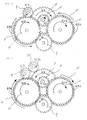
- Figure 6 shows the gear arrangement employed in the above embodiment, and it particularly shows the motor gear 14a', two primary gear wheels 50, transmission gear 130, secondary gear wheel 100, tip end gear 120 and two ring gears 22 provided on the outer cutting members 20.
- the gear G1 (which corresponds to the motor shaft gear 14a in Figures 2 and 3) is meshed with two gears G2a and G2b (each corresponding to the two primary gear wheels 50) which are installed side by side.
- the gear G3 (which corresponds to the transmission gear 130 in Figures 2 and 3) is meshed with one (G2a) of the two gears G2a and G2b and also with the gear G4 (which corresponds to the secondary gear wheel 100 in Figures 2 and 3).
- the gear G4' (which corresponds to the tip end gear 120) is provided on the same axis as the gear G4 (with the secondary drive shaft 110 in between) , and the gear G4' is meshed with two gears G5a and G5b (each corresponding to the ring gears 22 attached to the two outer cutting members 20 in Figures 2 and 3).
- the two inner cutting members are rotated in one direction N, and the two outer cutting members are rotated in another or opposite direction P.
- the inner cutting members and the outer cutting members are rotated in different or opposite directions from each other.
- Figure 7 shows a modification of the above embodiment; and in this embodiment of Figure 7, the inner and outer cutting members are rotated in the same direction.
- an auxiliary transmission gear G3a is interposed between and meshed with gear G3 (corresponding to the transmission gear 130) and the gear G4 (corresponding to the secondary gear wheel 100), so that the rotation of gear G3 is transmitted to the gear G4 via the auxiliary transmission gear G3a.
- the shaver according to the above embodiment that has two pairs of inner and outer cutting members has a structure that comprises:
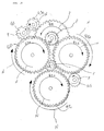
- Figure 8 shows the gear arrangement employed in the second embodiment of the present invention.
- three pairs of outer and inner cutting members are installed in an equilateral triangle (inverse equilateral triangle) configuration; and three inner cutting members are rotated in one direction and three outer cutting members are rotated in another direction which is opposite thereto.
- the basic structure of the second embodiment is the same as the first embodiment described above, and the second embodiment is an extension of the basic structure of Figures 2 and 3 from a two cutter system to three cutter system; accordingly, the second embodiment will be described with reference only to the gear engagement shown in this Figure 8.
- the gear G1 (which represents a motor shaft gear 14a in Figures 2 and 3) is provided at the center of three gears G2a, G2b and G2c (each representing primary gear wheel 50 in Figures 2 and 3) which are arranged in an inverse equilateral triangle shape and meshed therewith.
- the gear G3 (which represents a transmission gear 130 in Figures 2 and 3) is meshed with the gear G2a and also with gear G4 (which represents a secondary gear wheel 100 in Figures 2 and 3).
- Gear G4' (which represents a tip end gear 120 in Figures 2 and 3) is provided on the same axis as the gear G4 so as to be rotated thereby, and the gear G4' is meshed with two gears (G5a and G5b) of the three gears G5a, G5b and G5c (each representing the ring gears 22 of the three outer cutting members 20 in Figures 2 and 3) which are arranged, like the three gears G2a, G2b and G3c, in an inverse equilateral triangle shape.
- a relay gear G6 is additionally provided so as to mesh with the gear G5b and a gear G5c.
- the gear G6 is rotatably provided on the undersurface of the head frame 16 as shown in Figure 9 by way of the reference numeral 140 and is meshed with one (G5b) of two gears (G5a and G5b) and the remaining gear G5c (ring gear 22).
- the gears G5a, G5b and G5c are all rotated in the direction P, and the three outer cutting members having the ring gears 22 that correspond to the gears G5a, G5b and G5c are all rotated in the direction P.
- the three inner cutting members are rotated in one direction N, and the three outer cutting members are rotated in another direction P.
- the inner cutting members and the outer cutting members are rotated in different or opposite directions from each other.
- the embodiment shown in Figure 10 includes, in addition to the structure of Figure 8, an auxiliary transmission gear G3a is provided between the gear G3 (transmission gear) and gear G4 (secondary gear wheel) so that the auxiliary transmission gear G3a is meshed with these gears G3 and G4.
- the auxiliary transmission gear G3a is rotated in the direction N which causes the gear G4 (secondary gear wheel) to rotate in the direction P so that the gears G5a and G5b (ring gears 22), which are provided on the outer cutting members and meshed with the gear G4, are rotated in the direction N by the gear G4' which is rotated by the gear G4. Since the gear G5b is thus rotated in the direction N, the relay gear G6 is rotated in the direction P which causes the remaining gear G5c (ring gear 22) provided on the outer cutting member to rotate in the direction N.
- the shaver having three inner cutting members and three outer cutting members has a structure that comprises:
- Figure 11 schematically shows the gear arrangement of the third embodiment of the present invention in which one inner cutting member and one outer cutting member are provided so as to rotated in the same direction.
- the basic structure of the third embodiment is the same as the first and second embodiments described above and has a simplified structure compared to a two or three cutter system. Accordingly, the third embodiment will be described with reference only to the gear engagement shown in this Figure 11.
- the gear G1 or motor shaft gear 14a is rotated in one direction P; and since the gear G2 (representing a primary gear wheel 50) is meshed with this gear G1 (motor shaft gear 14a), the gear G2 is rotated in another (or opposite) direction N. Accordingly, the inner cutting member that is connected to a first drive shaft which is coaxially coupled to the gear G2 is rotated in the direction N by the gear 2 (primary gear wheel 50).
- gear G5 or the ring gear 22 of the outer cutting member which is meshed with the gear G4' is rotated in the direction P, and the outer cutting member to which the gear G5 or the ring gear 22 is attached is rotated in the direction P.
- the inner cutting member is rotated in one direction N, and the outer cutting member is rotated in another or opposite direction P.
- the inner cutting member and the outer cutting member are rotated in different or opposite directions from each other.
- Figure 12 shows a modification of the third embodiment shown in Figure 11; and in this modified embodiment, the inner cutting member and the outer cutting member are rotated in the same direction.
- an auxiliary transmission gear G3 (130a) is additionally provided between the gear G3 (transmission gear 130) and gear G4 (secondary gear wheel 100) so that the rotation of the gear G3 is transmitted to the gear G4 via the auxiliary transmission gear G3a.
- the gear G4 (secondary gear wheel 100) is rotated in the direction P when the gear G3 (transmission gear 130) is rotated in the direction P because of the presence of the auxiliary transmission gear G3a (130a), and so is the gear G4' (tip end gear 120).
- the gear G5 or the ring gear 22 of the outer cutting member that meshes the gear G4' (tip end gear 120) is rotated in the opposite direction N, and the inner cutting member is, therefore, rotated in the direction N, which is the same rotational direction of the outer cutting member.
- tooth shapes of the gears, the sizes or the diameters of the gears, and the number of teeth of each one of the gears shown in Figures 1 through 12 are merely illustrative for explanation purposes and do not represent the gear elements (such as the shapes of the gears and teeth, the sizes or the diameters of the gears, the gear ratio, the number of gear teeth, meshing configurations, etc.) of each one of the gears utilized in actual products. It is contemplated that any gear ratio and number of rotations of the inner and outer cutting members can be employed so as to secure the best shaving result.
- the outer cutting member(s) and the inner cutting member(s) can be rotated by different rotational numbers, it is preferable that the outer cutting member(s) be rotated slower than the inner cutting member(s). For instance, when the inner cutting member(s) is rotated at a speed of 2500 ⁇ 500 (or 2,000 - 3,000) rpm, it is desirable to set the outer cutting member(s) to be at a speed of less than 100 rpm, preferably at a speed of 40 - 80 rpm. In other words, a good shaving effect can be obtained when the inner cutting member(s) and the outer cutting member(s) are rotated at a rotational ratio of approximately 42 : 1.
- the transmission gear 130 (or gear G3) is rotated by the primary gear wheel(s) 50 (gear(s) G2, G2a, G2b, G2c) so as to rotate the secondary gear wheel 100 (or gear G4) which rotates the outer cutting member(s) 20 via the secondary drive gear 110, tip end gear 120 (gear G4') and ring gear(s) 22 (gear(s) G5, G5a, G5b, G5c)).
- the transmission gear 130 (G3) is directly rotated by the motor 14.
- the transmission gear 130 (G3) is coupled to the output shaft 14' of the motor 14 (instead of being rotatably journalled on the transmission spindle 12z) and meshed with the primary gear wheel(s) 50 and the secondary gear wheel 100 so as to rotate the primary and secondary drive shafts 60 and 110; in addition, a gear that corresponds to the motor shaft gear 14a (G1) is rotatably provided on the mounting plate 12a and meshed with the primary gear wheel(s) 50.
- the rotating outer cutting member(s) can raise the lying hair to introduce the raised hair into the slits (hair entry apertures) of the outer cutting member(s), so that shaving can be done extremely easily, efficiently and smoothly.
Landscapes
- Life Sciences & Earth Sciences (AREA)
- Forests & Forestry (AREA)
- Engineering & Computer Science (AREA)
- Mechanical Engineering (AREA)
- Dry Shavers And Clippers (AREA)
Applications Claiming Priority (2)
| Application Number | Priority Date | Filing Date | Title |
|---|---|---|---|
| US805446 | 1997-02-25 | ||
| US08/805,446 US6212776B1 (en) | 1997-02-25 | 1997-02-25 | Electric shaver |
Publications (2)
| Publication Number | Publication Date |
|---|---|
| EP0860247A1 true EP0860247A1 (fr) | 1998-08-26 |
| EP0860247B1 EP0860247B1 (fr) | 2002-09-11 |
Family
ID=25191594
Family Applications (1)
| Application Number | Title | Priority Date | Filing Date |
|---|---|---|---|
| EP98300330A Expired - Lifetime EP0860247B1 (fr) | 1997-02-25 | 1998-01-19 | Rasoir électrique |
Country Status (5)
| Country | Link |
|---|---|
| US (1) | US6212776B1 (fr) |
| EP (1) | EP0860247B1 (fr) |
| CA (1) | CA2227054C (fr) |
| DE (1) | DE69807763T2 (fr) |
| MX (1) | MX9801503A (fr) |
Cited By (6)
| Publication number | Priority date | Publication date | Assignee | Title |
|---|---|---|---|---|
| WO2004056539A1 (fr) * | 2002-12-19 | 2004-07-08 | Koninklijke Philips Electronics N.V. | Appareil de rasage |
| NL1036819C2 (nl) * | 2009-04-06 | 2010-10-07 | R N Machb B V | Scheerkop en scheerapparaat voorzien van een dergelijke scheerkop. |
| ITMI20120228A1 (it) * | 2012-02-16 | 2013-08-17 | Romano Rossoni | Rasoio elettrico con testine di contatto rotanti. |
| EP3115160A1 (fr) * | 2015-07-09 | 2017-01-11 | Izumi Products Company | Rasoir électrique rotatif |
| CN107042530A (zh) * | 2017-06-19 | 2017-08-15 | 苏州力佳达电子科技有限公司 | 一种双头式剃须刀 |
| EP4197721A1 (fr) * | 2021-12-14 | 2023-06-21 | Koninklijke Philips N.V. | Rotation d'élément de coupe externe d'une unité de rasage |
Families Citing this family (21)
| Publication number | Priority date | Publication date | Assignee | Title |
|---|---|---|---|---|
| US6584691B1 (en) * | 1999-10-08 | 2003-07-01 | Technology Innovations, Llc | Electric shaver having orbitally moving blades |
| US6553668B1 (en) * | 2002-05-16 | 2003-04-29 | Hy Steinberg | Rotary electric shaver |
| CN2647519Y (zh) * | 2003-06-17 | 2004-10-13 | 上海真博电器有限公司 | 四头双向电动剃须器 |
| US6976312B2 (en) * | 2004-05-13 | 2005-12-20 | Wiler Pennie A | Split-end hair clipper |
| US6901662B1 (en) * | 2004-07-28 | 2005-06-07 | Hy Steinberg | Rotary electric shaver with rotating screens |
| KR200385696Y1 (ko) * | 2004-12-14 | 2005-06-02 | 오태준 | 망회전전기면도기 |
| JP2006198093A (ja) * | 2005-01-19 | 2006-08-03 | Izumi Products Co | ロータリー式電気かみそり |
| US20080184562A1 (en) * | 2007-02-02 | 2008-08-07 | Ching-Tien Pi | Electric shaver with nose hair trimmer |
| JP4353260B2 (ja) * | 2007-02-23 | 2009-10-28 | パナソニック電工株式会社 | 脱毛装置 |
| JP4265666B2 (ja) * | 2007-02-23 | 2009-05-20 | パナソニック電工株式会社 | 脱毛装置 |
| US9027251B2 (en) | 2009-04-29 | 2015-05-12 | Spectrum Brands, Inc. | Rotary electric shaver |
| BR112012010751A2 (pt) * | 2009-11-09 | 2020-09-08 | Koninklijke Philips Elecronics N.V | aparelho para raspar a cabeça e barbeador |
| CN201525040U (zh) * | 2009-11-19 | 2010-07-14 | 上海真博电器有限公司 | 一种三刀头电动剃须刀 |
| US8397388B1 (en) * | 2011-11-03 | 2013-03-19 | Hy Steinberg | Rotary shaver platform rotation system |
| JP2014117381A (ja) * | 2012-12-14 | 2014-06-30 | Izumi Products Co | ロータリー式電気かみそり |
| US9266246B2 (en) * | 2012-12-31 | 2016-02-23 | Spectrum Brands, Inc. | Drive component for electric shaver |
| US10551332B2 (en) * | 2015-12-04 | 2020-02-04 | Exxonmobil Research And Engineering Company | Apparatus for determining the congealing point of a petroleum wax sample and methods therefor |
| EP3738730A1 (fr) * | 2019-05-14 | 2020-11-18 | Koninklijke Philips N.V. | Appareil de rasage avec commande de réglage d'un paramètre de fonctionnement |
| CN110788888A (zh) * | 2019-12-02 | 2020-02-14 | 王瑞 | 一种具有新型可转动式刀网的剃须刀 |
| CN112049903A (zh) * | 2020-09-21 | 2020-12-08 | 汪专兴 | 一种新型传动装置及剃须刀 |
| CN118952324A (zh) * | 2024-10-17 | 2024-11-15 | 浙江金达电机电器有限公司 | 全角度摇摆支架 |
Citations (2)
| Publication number | Priority date | Publication date | Assignee | Title |
|---|---|---|---|---|
| FR1192334A (fr) * | 1957-12-06 | 1959-10-26 | Rasoir perfectionné électrique ou mécanique | |
| EP0074684A2 (fr) * | 1981-09-11 | 1983-03-23 | Koninklijke Philips Electronics N.V. | Rasoir électrique |
Family Cites Families (13)
| Publication number | Priority date | Publication date | Assignee | Title |
|---|---|---|---|---|
| NL53921C (fr) * | 1938-11-10 | |||
| NL59579C (fr) * | 1939-02-23 | |||
| BE459811A (fr) * | 1943-10-27 | |||
| US2742694A (en) * | 1950-08-02 | 1956-04-24 | Charles G Stone | Mechanical shaver |
| US2965966A (en) * | 1958-10-27 | 1960-12-27 | Joseph H Jacobs | Electric razor with multiple rotary cutter head and oscillating combs |
| CH376798A (de) * | 1960-04-28 | 1964-04-15 | Spengler Max | Trockenrasierapparat mit Schersieb |
| DE1173817B (de) * | 1961-12-01 | 1964-07-09 | Dr Med Anselm Ritschl | Trockenrasiergeraet mit auf der zu rasierenden Haut abrollbaren Kontaktscherfolien |
| FR1428943A (fr) * | 1965-03-23 | 1966-02-18 | Rasoir électrique | |
| US3715803A (en) * | 1971-02-16 | 1973-02-13 | T Tyler | Rotary dry shaver with tiltable shear plates |
| US4089110A (en) * | 1976-03-08 | 1978-05-16 | Rasco Darius K | Shaving means |
| DE3843936C1 (fr) * | 1988-12-24 | 1990-05-31 | Braun Ag, 6000 Frankfurt, De | |
| NL8900071A (nl) * | 1989-01-12 | 1990-08-01 | Philips Nv | Scheerapparaat. |
| JP3521089B2 (ja) * | 1993-02-12 | 2004-04-19 | 株式会社泉精器製作所 | 電気かみそり |
-
1997
- 1997-02-25 US US08/805,446 patent/US6212776B1/en not_active Expired - Lifetime
-
1998
- 1998-01-15 CA CA002227054A patent/CA2227054C/fr not_active Expired - Fee Related
- 1998-01-19 DE DE69807763T patent/DE69807763T2/de not_active Expired - Lifetime
- 1998-01-19 EP EP98300330A patent/EP0860247B1/fr not_active Expired - Lifetime
- 1998-02-24 MX MX9801503A patent/MX9801503A/es not_active IP Right Cessation
Patent Citations (2)
| Publication number | Priority date | Publication date | Assignee | Title |
|---|---|---|---|---|
| FR1192334A (fr) * | 1957-12-06 | 1959-10-26 | Rasoir perfectionné électrique ou mécanique | |
| EP0074684A2 (fr) * | 1981-09-11 | 1983-03-23 | Koninklijke Philips Electronics N.V. | Rasoir électrique |
Cited By (9)
| Publication number | Priority date | Publication date | Assignee | Title |
|---|---|---|---|---|
| WO2004056539A1 (fr) * | 2002-12-19 | 2004-07-08 | Koninklijke Philips Electronics N.V. | Appareil de rasage |
| CN1729083B (zh) * | 2002-12-19 | 2011-10-05 | 皇家飞利浦电子股份有限公司 | 剃削设备 |
| NL1036819C2 (nl) * | 2009-04-06 | 2010-10-07 | R N Machb B V | Scheerkop en scheerapparaat voorzien van een dergelijke scheerkop. |
| ITMI20120228A1 (it) * | 2012-02-16 | 2013-08-17 | Romano Rossoni | Rasoio elettrico con testine di contatto rotanti. |
| EP3115160A1 (fr) * | 2015-07-09 | 2017-01-11 | Izumi Products Company | Rasoir électrique rotatif |
| US10195751B2 (en) | 2015-07-09 | 2019-02-05 | Izumi Products Company | Rotary electric shaver |
| CN107042530A (zh) * | 2017-06-19 | 2017-08-15 | 苏州力佳达电子科技有限公司 | 一种双头式剃须刀 |
| EP4197721A1 (fr) * | 2021-12-14 | 2023-06-21 | Koninklijke Philips N.V. | Rotation d'élément de coupe externe d'une unité de rasage |
| WO2023110461A1 (fr) * | 2021-12-14 | 2023-06-22 | Koninklijke Philips N.V. | Rotation d'un élément de coupe externe d'une unité de rasage |
Also Published As
| Publication number | Publication date |
|---|---|
| CA2227054C (fr) | 2002-05-21 |
| US6212776B1 (en) | 2001-04-10 |
| EP0860247B1 (fr) | 2002-09-11 |
| CA2227054A1 (fr) | 1998-08-25 |
| DE69807763D1 (de) | 2002-10-17 |
| DE69807763T2 (de) | 2004-02-19 |
| MX9801503A (es) | 1998-11-30 |
Similar Documents
| Publication | Publication Date | Title |
|---|---|---|
| EP0860247B1 (fr) | Rasoir électrique | |
| EP0611043B1 (fr) | Rasoir électrique | |
| KR0132418B1 (ko) | 환상치차에 의한 동력전달장치를 갖는 예초기 | |
| US5983501A (en) | Electric shaver | |
| CA2311697C (fr) | Rasoir electrique a tetes rotatives | |
| US5044146A (en) | Oscillating-type mowing apparatus | |
| JPS60212188A (ja) | ひげ剃りユニツト | |
| WO2003097309A1 (fr) | Rasoir electrique rotatif | |
| KR100209006B1 (ko) | 전기 면도기 | |
| JPH0617432U (ja) | バリカン形刈払機 | |
| JPH10328438A (ja) | 電気かみそり | |
| EP4448236B1 (fr) | Rotation d'élément de coupe externe d'une unité de rasage | |
| JP4340336B2 (ja) | 電気かみそり | |
| EP0318103B1 (fr) | Rasoir électrique | |
| CN1132725C (zh) | 电动剃须刀 | |
| HK1021712A1 (en) | Electric shaver | |
| KR100500311B1 (ko) | 전기면도기의 칼날 연마장치 | |
| KR200324345Y1 (ko) | 전기면도기의 칼날 연마장치 | |
| JPH0371723U (fr) | ||
| JPH0184533U (fr) | ||
| MXPA98002537A (en) | Electric scraper | |
| JPS6344713U (fr) | ||
| JPH0633416U (ja) | バリカン形刈払機 | |
| JPS61118701U (fr) | ||
| JPH03123468U (fr) |
Legal Events
| Date | Code | Title | Description |
|---|---|---|---|
| PUAI | Public reference made under article 153(3) epc to a published international application that has entered the european phase |
Free format text: ORIGINAL CODE: 0009012 |
|
| AK | Designated contracting states |
Kind code of ref document: A1 Designated state(s): DE FR GB IT NL SE |
|
| AX | Request for extension of the european patent |
Free format text: AL;LT;LV;MK;RO;SI |
|
| 17P | Request for examination filed |
Effective date: 19980827 |
|
| AKX | Designation fees paid |
Free format text: DE FR GB IT NL SE |
|
| RBV | Designated contracting states (corrected) |
Designated state(s): DE FR GB IT NL SE |
|
| 17Q | First examination report despatched |
Effective date: 20001115 |
|
| GRAG | Despatch of communication of intention to grant |
Free format text: ORIGINAL CODE: EPIDOS AGRA |
|
| GRAG | Despatch of communication of intention to grant |
Free format text: ORIGINAL CODE: EPIDOS AGRA |
|
| GRAG | Despatch of communication of intention to grant |
Free format text: ORIGINAL CODE: EPIDOS AGRA |
|
| GRAH | Despatch of communication of intention to grant a patent |
Free format text: ORIGINAL CODE: EPIDOS IGRA |
|
| GRAH | Despatch of communication of intention to grant a patent |
Free format text: ORIGINAL CODE: EPIDOS IGRA |
|
| GRAA | (expected) grant |
Free format text: ORIGINAL CODE: 0009210 |
|
| AK | Designated contracting states |
Kind code of ref document: B1 Designated state(s): DE FR GB IT NL SE |
|
| REG | Reference to a national code |
Ref country code: GB Ref legal event code: FG4D |
|
| REF | Corresponds to: |
Ref document number: 69807763 Country of ref document: DE Date of ref document: 20021017 |
|
| PG25 | Lapsed in a contracting state [announced via postgrant information from national office to epo] |
Ref country code: SE Free format text: LAPSE BECAUSE OF FAILURE TO SUBMIT A TRANSLATION OF THE DESCRIPTION OR TO PAY THE FEE WITHIN THE PRESCRIBED TIME-LIMIT Effective date: 20021211 |
|
| ET | Fr: translation filed | ||
| PLBE | No opposition filed within time limit |
Free format text: ORIGINAL CODE: 0009261 |
|
| STAA | Information on the status of an ep patent application or granted ep patent |
Free format text: STATUS: NO OPPOSITION FILED WITHIN TIME LIMIT |
|
| 26N | No opposition filed |
Effective date: 20030612 |
|
| PGFP | Annual fee paid to national office [announced via postgrant information from national office to epo] |
Ref country code: IT Payment date: 20120130 Year of fee payment: 15 |
|
| PGFP | Annual fee paid to national office [announced via postgrant information from national office to epo] |
Ref country code: NL Payment date: 20120130 Year of fee payment: 15 |
|
| REG | Reference to a national code |
Ref country code: NL Ref legal event code: V1 Effective date: 20130801 |
|
| PG25 | Lapsed in a contracting state [announced via postgrant information from national office to epo] |
Ref country code: NL Free format text: LAPSE BECAUSE OF NON-PAYMENT OF DUE FEES Effective date: 20130801 |
|
| PG25 | Lapsed in a contracting state [announced via postgrant information from national office to epo] |
Ref country code: IT Free format text: LAPSE BECAUSE OF NON-PAYMENT OF DUE FEES Effective date: 20130119 |
|
| REG | Reference to a national code |
Ref country code: FR Ref legal event code: PLFP Year of fee payment: 19 |
|
| REG | Reference to a national code |
Ref country code: FR Ref legal event code: PLFP Year of fee payment: 20 |
|
| PGFP | Annual fee paid to national office [announced via postgrant information from national office to epo] |
Ref country code: DE Payment date: 20170120 Year of fee payment: 20 Ref country code: FR Payment date: 20170120 Year of fee payment: 20 |
|
| PGFP | Annual fee paid to national office [announced via postgrant information from national office to epo] |
Ref country code: GB Payment date: 20170119 Year of fee payment: 20 |
|
| REG | Reference to a national code |
Ref country code: DE Ref legal event code: R071 Ref document number: 69807763 Country of ref document: DE |
|
| REG | Reference to a national code |
Ref country code: GB Ref legal event code: PE20 Expiry date: 20180118 |
|
| PG25 | Lapsed in a contracting state [announced via postgrant information from national office to epo] |
Ref country code: GB Free format text: LAPSE BECAUSE OF EXPIRATION OF PROTECTION Effective date: 20180118 |