EP0860637A1 - Lagerdichtung mit gleichmässiger Flüssigkeitsspülung - Google Patents
Lagerdichtung mit gleichmässiger Flüssigkeitsspülung Download PDFInfo
- Publication number
- EP0860637A1 EP0860637A1 EP98102008A EP98102008A EP0860637A1 EP 0860637 A1 EP0860637 A1 EP 0860637A1 EP 98102008 A EP98102008 A EP 98102008A EP 98102008 A EP98102008 A EP 98102008A EP 0860637 A1 EP0860637 A1 EP 0860637A1
- Authority
- EP
- European Patent Office
- Prior art keywords
- annular volume
- seal
- housing
- shaft
- flange
- Prior art date
- Legal status (The legal status is an assumption and is not a legal conclusion. Google has not performed a legal analysis and makes no representation as to the accuracy of the status listed.)
- Granted
Links
- 239000012530 fluid Substances 0.000 title claims abstract description 103
- 238000010926 purge Methods 0.000 title claims abstract description 82
- 239000000356 contaminant Substances 0.000 claims abstract description 20
- 238000009420 retrofitting Methods 0.000 claims description 6
- 239000000919 ceramic Substances 0.000 claims description 5
- 238000004891 communication Methods 0.000 claims description 4
- 238000005524 ceramic coating Methods 0.000 claims description 3
- 238000000034 method Methods 0.000 claims 6
- 239000011248 coating agent Substances 0.000 claims 2
- 238000000576 coating method Methods 0.000 claims 2
- 241000283216 Phocidae Species 0.000 description 74
- 239000002826 coolant Substances 0.000 description 28
- 238000003754 machining Methods 0.000 description 21
- 229910052751 metal Inorganic materials 0.000 description 12
- 239000002184 metal Substances 0.000 description 12
- 239000000463 material Substances 0.000 description 8
- 230000003068 static effect Effects 0.000 description 8
- 229910000831 Steel Inorganic materials 0.000 description 6
- 230000002411 adverse Effects 0.000 description 6
- 239000010959 steel Substances 0.000 description 6
- 230000000694 effects Effects 0.000 description 5
- 239000007788 liquid Substances 0.000 description 5
- 239000000843 powder Substances 0.000 description 5
- 238000009825 accumulation Methods 0.000 description 4
- 238000005406 washing Methods 0.000 description 3
- 229920002449 FKM Polymers 0.000 description 2
- PXHVJJICTQNCMI-UHFFFAOYSA-N Nickel Chemical compound [Ni] PXHVJJICTQNCMI-UHFFFAOYSA-N 0.000 description 2
- GWEVSGVZZGPLCZ-UHFFFAOYSA-N Titan oxide Chemical compound O=[Ti]=O GWEVSGVZZGPLCZ-UHFFFAOYSA-N 0.000 description 2
- 229910052782 aluminium Inorganic materials 0.000 description 2
- XAGFODPZIPBFFR-UHFFFAOYSA-N aluminium Chemical compound [Al] XAGFODPZIPBFFR-UHFFFAOYSA-N 0.000 description 2
- 238000010276 construction Methods 0.000 description 2
- 230000007812 deficiency Effects 0.000 description 2
- 229920001971 elastomer Polymers 0.000 description 2
- 239000004519 grease Substances 0.000 description 2
- 239000000383 hazardous chemical Substances 0.000 description 2
- 239000000314 lubricant Substances 0.000 description 2
- 239000010687 lubricating oil Substances 0.000 description 2
- 230000002093 peripheral effect Effects 0.000 description 2
- 238000007789 sealing Methods 0.000 description 2
- 238000004381 surface treatment Methods 0.000 description 2
- 238000011282 treatment Methods 0.000 description 2
- 229910000906 Bronze Inorganic materials 0.000 description 1
- ZOKXTWBITQBERF-UHFFFAOYSA-N Molybdenum Chemical compound [Mo] ZOKXTWBITQBERF-UHFFFAOYSA-N 0.000 description 1
- 230000009286 beneficial effect Effects 0.000 description 1
- 239000010974 bronze Substances 0.000 description 1
- 238000009833 condensation Methods 0.000 description 1
- 230000005494 condensation Effects 0.000 description 1
- 230000009133 cooperative interaction Effects 0.000 description 1
- KUNSUQLRTQLHQQ-UHFFFAOYSA-N copper tin Chemical compound [Cu].[Sn] KUNSUQLRTQLHQQ-UHFFFAOYSA-N 0.000 description 1
- 230000002596 correlated effect Effects 0.000 description 1
- 230000000875 corresponding effect Effects 0.000 description 1
- 230000007423 decrease Effects 0.000 description 1
- 230000007613 environmental effect Effects 0.000 description 1
- 230000009931 harmful effect Effects 0.000 description 1
- 238000010438 heat treatment Methods 0.000 description 1
- 238000002955 isolation Methods 0.000 description 1
- 239000000203 mixture Substances 0.000 description 1
- 229910052750 molybdenum Inorganic materials 0.000 description 1
- 239000011733 molybdenum Substances 0.000 description 1
- 229910052759 nickel Inorganic materials 0.000 description 1
- 239000003921 oil Substances 0.000 description 1
- 239000002245 particle Substances 0.000 description 1
- 230000009528 severe injury Effects 0.000 description 1
- 239000007921 spray Substances 0.000 description 1
- 238000005507 spraying Methods 0.000 description 1
- 239000004408 titanium dioxide Substances 0.000 description 1
Images


Classifications
-
- F—MECHANICAL ENGINEERING; LIGHTING; HEATING; WEAPONS; BLASTING
- F16—ENGINEERING ELEMENTS AND UNITS; GENERAL MEASURES FOR PRODUCING AND MAINTAINING EFFECTIVE FUNCTIONING OF MACHINES OR INSTALLATIONS; THERMAL INSULATION IN GENERAL
- F16J—PISTONS; CYLINDERS; SEALINGS
- F16J15/00—Sealings
- F16J15/16—Sealings between relatively-moving surfaces
- F16J15/34—Sealings between relatively-moving surfaces with slip-ring pressed against a more or less radial face on one member
- F16J15/3436—Pressing means
- F16J15/3456—Pressing means without external means for pressing the ring against the face, e.g. slip-ring with a resilient lip
-
- F—MECHANICAL ENGINEERING; LIGHTING; HEATING; WEAPONS; BLASTING
- F16—ENGINEERING ELEMENTS AND UNITS; GENERAL MEASURES FOR PRODUCING AND MAINTAINING EFFECTIVE FUNCTIONING OF MACHINES OR INSTALLATIONS; THERMAL INSULATION IN GENERAL
- F16C—SHAFTS; FLEXIBLE SHAFTS; ELEMENTS OR CRANKSHAFT MECHANISMS; ROTARY BODIES OTHER THAN GEARING ELEMENTS; BEARINGS
- F16C33/00—Parts of bearings; Special methods for making bearings or parts thereof
- F16C33/72—Sealings
- F16C33/76—Sealings of ball or roller bearings
Definitions
- This invention relates to a bearing seal, and more particularly to a bearing seal with improved capability for isolating the bearings and other internal components of a rotating shaft or machine, such as a machine tool spindle.
- a machine tool motor rotatably drives a spindle shaft within a bearing housing, with the motor operatively coupled to one end of the spindle shaft.
- the opposite end of the spindle shaft extends outside of the bearing housing, and it holds a chuck or other tool-holding device which rotates with the spindle shaft to perform a machining operation on a workpiece.
- the bearing housing and the rotatable spindle shaft must cooperate to precisely rotate the tool-holder about a desired axis, such as vertical or horizontal, over relatively long periods of time.
- a machining "assembly" line may include as many as three hundred successive machining operations. If one machine tool goes down, due for instance to machining inaccuracy resulting from problems with the spindle bearings or the spindle itself, it becomes necessary to shut down the entire line, at tremendous cost to the manufacturer.
- one area of susceptibility is the seal between the inside of the stationary bearing housing and the rotatable spindle shaft, where the tool-holding end of the spindle shaft extends out of the housing. It is absolutely critical to maintain an effective seal at this joint.
- labyrinth-type bearing seals to isolate the inner portions from the outer portions of a spindle shaft of a machine tool.
- These seals typically include a stator (sometimes referred to as a cap) which is mounted, as by press fitting, into the bearing housing, and which includes radially oriented labyrinth grooves.
- the labyrinth passage could be formed by the spacing between the stationary and the rotary parts.
- a rotor fits axially into the stator, revolves with the spindle, and is held in place on the rotating member by static drive rings and/or a tight fit.
- the labyrinth structure is designed to require multiple changes in fluid flow direction, with accompanying changes in fluid pressure, with the objective of minimizing the possibility of coolant ingress to the bearing.
- the structure also includes an expulsion port designed to expel any fluid contaminant that may work its way into the seal structure.
- U.S. Patent Number 5,378,000 shows one such labyrinth-type bearing seal.
- labyrinth-type bearing seals have proved suitable for some applications, they have also experienced deficiencies in other important applications.
- One reason for these deficiencies relates to an increase in the performance expectations for bearing seals for machine tool spindles. More specifically, over the past five to ten years there has been an increased awareness of the potential hazards of overexposure of human operators to machine tool coolants and the particles/chips generated by machining. For this reason, and because almost all machine tool coolants are classified as hazardous materials from an environmental standpoint, there has been a movement toward enclosing the machining area of machine tools, usually within some type of movable or closable shroud, or enclosure. The shroud reduces exposure of the human operator to potentially hazardous materials such as liquid coolant, machine tool lubricating oil or metal chips produced during machining operations.
- the orientation and/or shape of the shroud may cause an increase in the accumulation of metal chips near the bearing seal. Even though the relatively large metal chips may be too large to work their way past the seal, they may sufficiently interfere with proper operation of the seal so that during use the structure becomes more susceptible to coolant ingress.
- the labyrinth seal has other disadvantages. Because of the relatively complex labyrinth structure and the close tolerances, the machining costs for labyrinth-type seals is relatively high. Also, since the labyrinth structure remains open, there is always a possibility of coolant ingress into the labyrinth, and eventually to the bearings. Most labyrinth seals include at least one expulsion port, to allow outflow of contaminant. Unfortunately, the expulsion port provides another entry opportunity for metal chips.
- rubbing seals which typically include a rubber lip.
- One advantage of a rubbing seal is the positive circumferential contact along the seal joint.
- rubbing seals have rotational speed limitations, due to excessive heat build up from friction which adversely affects spindle performance.
- Some seal configurations have been adapted to accommodate the features of the labyrinth seal and the rubbing seal, with the labyrinth portion located closer to the joint than the rubbing seal.
- purge fluid from the bearing housing is introduced between the labyrinth seal portion and the rubbing seal portion during operation, in an effort to prevent ingress of coolant or other potential contaminants. While the purge fluid may improve the effectiveness of the labyrinth seal portion, the labyrinth seal joint still remains open when the purge fluid is turned off, so the labyrinth portion of the seal is still susceptible to liquid ingress. This problem is also true with respect to a labyrinth/mini-maze seal. Moreover, the use of purge fluid in combination with a labyrinth/rubbing seal structure still does not solve the heating problem of the rubbing seal, so there are still speed limitations.
- Another bearing seal uses a labyrinth in combination with a rotatable contact seal, with compressed gas introduced between the contacting surfaces to lift the seal and form a gas cushion between the surfaces.
- the contact seal is relied on to prevent ingress.
- the gas cushion is relied on.
- the success of this seal depends upon centrifugal forces which cause the seal to move out of contact with the opposed contacting surface, and outflow of the compressed gas which forms the gas cushion.
- the present invention achieves the above-stated objects via a bearing housing/seal structure with a tangential fluid passage formed in the end of the housing for introducing, in a tangential direction, purge fluid into the annular volume surrounding a rotatable shaft, to produce circumferential flow of the purge fluid and a radially uniform pressure gradient for the purge fluid around the shaft. Under sufficient pressure build up, this radially uniform pressure gradient around the shaft assures peripherally uniform outflow of purge fluid through the seal.
- the structure includes a seal with a flexible lip which contacts an opposing surface of a flange of the rotatable shaft, at one axial end of a hollow annular volume residing between the housing and the shaft.
- the lip contacts the shaft at a radial distance greater than the radial dimension of the rest of the annular volume, where fluid pressure build up is greatest.
- Build up of purge fluid pressure within the annular volume eventually causes the resilient lip of the seal to flex away from the flange surface. This opens the annular volume to atmosphere, resulting in an outward flow of purge fluid in a substantially uniform manner around the entire periphery of the shaft, due to the uniform pressure gradient produced by introducing the purge fluid tangentially via the tangential passage.
- This invention improves the seal capability and reliability of bearing seals, such as spindle bearing seals, by actively and uniformly preventing ingress of contaminants around the entire circumference of the spindle, under static and dynamic conditions.
- the uniform outward flow of purge fluid affirmatively prevents ingress of contaminants, even under adverse conditions such as heavy and continuous coolant flow or heavy buildup of metal chips.
- this invention positively prevents contaminant ingress in a manner which does not adversely affect normal rotational operation of a shaft, as for instance a precision spindle, primarily because the seal structure promotes a circumferentially uniform pressure gradient for the purge fluid. Also, because of the relatively simple structural configuration of the seal components, this invention represents a relatively inexpensive bearing seal which may be readily adapted to spindles and to other applications, and for retrofitting these types of seals in the field.
- a bearing seal includes an annular bearing cap, a seal with a resilient lip and a spindle flange.
- the bearing cap is adapted to be secured to a bearing housing, where the spindle shaft exits the housing.
- the seal resides in a recess machined in an outer surface of the cap, and the resilient lip extends outwardly therefrom, in a direction away from the bearing housing.
- the spindle flange is spaced from the cap but engaged by the lip.
- the cap and bearing housing have machined bores which cooperatively define an external passage in fluid communication with the annular volume surrounding the spindle shaft.
- the external passage terminates at its innermost end with a section which is oriented substantially tangential to the annular volume.
- the annular volume surrounding the spindle shaft has three distinct sections of different radii, all in fluid communication, as defined by the radially internal configuration of the bearing cap. But for each section, the radial dimension is less than the radial dimension of the peripheral region where the seal lip engages the spindle flange.
- the tangential section of the passage feeds the purge fluid to the section of the annular volume which is axially farthest away from the flange.
- the structural configuration of the cap, the seal and the spindle flange, including the external passage, and the flow parameters, i.e. the flow rate, pressure, temperature, humidity level, particulate level, or volume, etc., may be varied depending upon the particular circumstances of operation.
- the invention contemplates mounting the seal on the flange, i.e. the rotor, instead of the cap, i.e. the stator, to produce the same sealing effect under static and dynamic conditions.
- the invention contemplates making the stator/seal/rotor a separately available component.
- the stator could be designed structurally to fit into the end of a bearing housing, preferably with the external passage extending in its entirety through the stator.
- the rotor could then be sized to be fixedly secured, i.e. via threadable connection or a press fit, around the outer circumference of the shaft where the shaft exits the housing.
- the cap itself could be an integral part of the bearing housing, rather than a separate component. In other words, the cap refers to the end of the bearing housing, regardless of whether or not it is a detachable component.
- the invention contemplates various types of purge fluid, either liquid (with various viscosities) or gas.
- the invention also contemplates other applications for this bearing seal, since the principles of circumferentially uniform purge fluid pressure and peripherally uniform outward purge fluid flow can be applied to a wide variety of devices which employ a rotatable shaft supported by bearings and require bearing protection against egress of bearing lubricant, typically grease or small oil reservoirs, and ingress of contaminants.
- one or more additional passages could be employed, with purge fluid tangentially introduced therethrough.
- the purge fluid could be flowed in the direction of shaft rotation, or opposite thereto, or even in both directions.
- Fig. 1 is a longitudinal side view, in partial cross-section, which schematically shows a spindle, a spindle housing and a spindle bearing seal in accordance with a first preferred embodiment of the invention.
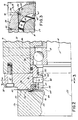
- Fig. 2 is an enlarged longitudinal cross-sectional view of the area bracketed in Fig. 1.
- Fig. 3 is a transverse cross-sectional view taken along lines 3-3 of Fig. 2.
- Fig. 4 is an enlarged longitudinal cross sectional view, similar to Fig. 2, showing a second preferred embodiment of the invention.
- Fig. 5 is another enlarged longitudinal cross sectional view, similar to Figs. 2 and 4, showing a third preferred embodiment of the invention.
- Fig. 1 schematically shows a machine tool, designated generally by reference numeral 10, supported on a support surface 11 and partially enclosed by a shroud 12 to contain the machining area.
- the machine tool 10 includes a spindle shaft 14, housed within a spindle housing 16 and rotatable with respect thereto via spaced bearings 18.
- a first end 20 of the spindle shaft 14 is operatively connected to a rotatable drive mechanism.
- the first end 20 is operatively connected to a belt 22 which is in turn connectable to a motor (not shown), for rotatably driving the spindle shaft 14 about an axis 23.
- spindle shaft 14 may be rotatably driven by an integral motor, or by gears which are in turn operatively connected to a gear motor, or any other type of rotatable drive mechanism, which could be located within the housing 16.
- An opposite second end 24 of the spindle shaft 14 includes a chuck 26 or other tool holding device, which in turn holds a tool 28 for machining the workpiece 30.
- Fig. 1 shows a tubular workpiece 30 and a tool 28 shaped to accommodate the tubular workpiece 30.
- the invention contemplates various other types of machining tools 28 or tool holding devices 26 located at the working end 24 of a spindle shaft 14.
- the machine tool 10 includes a coolant hose 32 mounted adjacent the machining area, for directing a flow of coolant stream 34 toward the location where the tool 28 contacts the workpiece 30, to reduce friction and heat build up during machining of the workpiece 30.
- a coolant hose 32 mounted adjacent the machining area, for directing a flow of coolant stream 34 toward the location where the tool 28 contacts the workpiece 30, to reduce friction and heat build up during machining of the workpiece 30.
- metal chips 35 During machining, it is common for metal chips 35 to fly off in all directions from the workpiece 30. This can result in accumulation of the chips 35 on nearby horizontal surfaces, such as the top surface of the spindle housing 16, as shown in Fig. 1.
- the second end 24 of the spindle shaft 14 includes a flange 36 which is axially spaced from an annular bearing cap 38 rigidly secured to the spindle housing 16 by bolts 40.
- annular refers to the radially internal shape, not necessarily the external.
- An annular, flat ring-shaped volume 42 resides between an internal surface 50 of the rotatable flange 36 and the stationary bearing cap 38.
- a seal 44 resides within a complementary-shaped recess 45 in the bearing cap 38, and the seal 44 includes a flexible lip 46 which spans the volume 42 and contacts a region 58 of the inwardly directed surface 50 of the flange 36.
- the radially internal surface dimensions of the bearing cap 38 define an annular volume 48 between the spindle shaft 14 and the bearing cap 38, or more particularly, the portion of the spindle shaft 14 which resides within the housing 16.
- An external passage 70 extends from the annular volume to the outside surface of the bearing housing 16.
- Fig. 2 shows the flange 36, the bearing cap 38 and the seal 44 in greater detail. It is to be understood that the sealing features shown in Fig. 2, i.e. primarily the flange 36 and the lip 46, extend circumferentially around the spindle shaft 14. More specifically, Fig. 2 shows the seal 44 in a static position with the lip 46 in contact with the internal surface 50 of the flange 36, during a condition of insufficient internal fluid pressure to cause deflection. Fig. 2 also shows, in phantom, via reference numeral 54, a flexed position for the lip 46 to indicate its capability for flexing out of contact with the internal surface 50 of flange 36. This occurs under sufficient purge fluid pressure within annular volume 48, or during rotation of shaft 14 under sufficient pressure build up in combination with centrifugal force. The open space behind the lip 46 also catches chips and prevents undesirable ingress.
- seals 44 may be suitable for this invention, so long as the seal 44 includes a flexible lip 46 capable of flexing outwardly out of contact with the flange 36.
- V-Ring seal supplied by C. R. Seals, particularly C. R. Stock No. 401104, which applicant understands is made of a material commercially available from DuPont under the name Viton®. To the best of applicant's knowledge, these V-Ring seals have not previously been mounted on the stationary portion, or stator, of a bearing seal.
- the structure is designed to be mounted on the rotor, because centrifugal force caused by rotation of the seal 44 (other than the lip 46) is what produces the flexing effect for the lip 46. It is important that the contacting region 58 and the lip 46 be in contact at a position radially outside of the annular volume 48. Thus, the lip 46 contacts the flange 36 at a radial dimension which is preferably greater than any other radial dimension of annular volume 48.
- seal 44 Because of the shape of the seal 44, coolant or contaminant flow directly into volume 42 will contact the lip 46, thereby urging the lip 46 into contact with region 58. This has the effect of making the seal 44 more rigid, to enhance the localized effectiveness of the seal 44 and to help prevent contaminant ingress into volume 48. If the seal 44 and lip 46 are made of a relatively stiff material, there will be less outward flow, less circumferential fluid flow, with higher pressure in volume 48. If the material for the lip 46 is more flexible, the pressure inside volume 48 will be somewhat lower and the outward flow of purge fluid and the circumferential flow will be greater.
- the hollow volume 48 is enclosed by a circumferential rib 49, which has a relatively tight clearance, i.e., about 0.002", with the shaft 14 to prevent excessive air flow between the volume 48 and the bearing 18.
- the ring-shaped volume 42 has its smallest axial dimension adjacent the outer periphery of flange 36.
- the outer diameters of the cap 38 and the flange 36 are equal, to minimize deflection of chips into volume 42. They may even be made to angle outwardly, to further minimize the occurrence of chip ingress.
- the internal surface 50 of flange 36 includes a chamfer 56 just peripherally outside of a contact region 58 of the internal surface 50. Having a thinner outer section for the flat ring-shaped volume 42 minimizes the volume for possible ingress of contaminants, while the chamfer 56 provides a deflection surface for outwardly expelled contaminants, and also provides additional space between the flange 36 and the cap 38 to permit flexing of the lip 46 of the seal 44.
- this circumferential contact region 58 of the flange 36 is provided with a ceramic surface treatment prior to assembly.
- this region 58 is heat sprayed with a self-bonding powder such as Metco 447NS, which is a mixture of aluminum, nickel and molybdenum.
- a ceramic bonding powder such as Metco ceramic powder no. 102, or another material which is believed to be an equivalent, such as PAC 702, a titanium dioxide powder.
- the powder is sprayed on with heat, as with a thermospray gun, and except for region 58, the rest of the internal surface 50 of the flange 36 is masked, thereby to confine this surface treatment to region 58.
- the region 58 is provided with a finish grind, such as a (32) finish grind.
- This treatment provides a circumferential ceramic coating with a thickness of about 0.010-0.012" for region 58 of flange 36.
- This ceramic coating reduces wear between the internal surface 50 and the lip 46, as would occur over time via operation of the spindle shaft 14 without sufficient fluid purge pressure to deflect lip 46. Treatments of this type are typically used in the industry to minimize surface wear when using rubbing seals. All other surfaces preferably are provided with a (63) finish, or finer.
- the invention contemplates mounting the seal 44 device on the rotor, i.e. the flange 36, rather than the stator, i.e. the cap 38.
- this variation would probably require that something other than the V-Ring be used as the seal 44, since rotation of the V-Ring causes flexing of the lip 46.
- Fig. 2 also shows that the annularly-shaped internal volume 48, which resides between the spindle shaft 14 and the bearing cap 38, actually has three distinct regions, a first region 62, a second region 64 and a third region 66. Again, each of these regions 62, 64, 66 has a radial dimension which is less than the radial dimension where the lip 46 contacts flange 36. The first region 62 of volume 48 has the greatest radial dimension. Optimum fluid purge effectiveness should be determined by varying the parameters of these regions. If region 62 or another part of the volume 48 has too great of a radial dimension, there may be an excessive circumferential pressure and a restricted overall purge fluid flow rate. On the other hand, too small of a radial dimension may inhibit the obtaining of a uniform pressure gradient within the annular volume 48.
- the bearing housing 16, which effectively includes the cap 38, has an external passage, designated generally by reference numeral 70, which extends from the internal volume 48 to outside the housing 16. More specifically, the external passage 70 includes, at its innermost section, a tangentially-directed bore 74 (tangential to first region 62, best shown in Fig. 3), and an axially-directed bore 76 formed in the bearing cap 38.
- the axially-directed bore 76 is aligned with an axially-directed bore 78 in the bearing housing 16, and an o-ring 82 is compressed at the interface between the bearing housing 16 and the bearing cap 38 to surround the aligned axial bores 76 and 78.
- the axial bore 78 in spindle housing 16 in turn communicates with a radially-oriented bore 86 in the spindle housing 16.
- a plug 84 (Fig. 3) caps off the end of bore 74.
- a pressurized fluid source (not shown) communicates with external passage 70 at an outer end thereof, outside the spindle housing 16, to supply pressurized purge fluid to the annular volume 48.
- Fig. 4 shows a second preferred embodiment of the invention, which is of slightly simpler construction. Components similar to those of the first embodiment have the same last two numerals, but are referred to with three digit numbers in the 100s.
- the seal 144 includes a stiff internal spine 147, such as steel or aluminum, encapsulated within a rubber or Viton type material, which is then press fit into a relatively simple ridge 145 machined in the cap 138.
- Fig. 5 shows a third preferred embodiment (with reference numerals in the 200s), wherein the seal 244 is entirely metal, such as steel or bronze. This construction may be needed if the environment will not permit a non-metallic seal.
- the lip 46 resides in contact with the flange 36 to provide a positive seal between the spindle flange 36 and the bearing cap 38 around the entire circumference.
- the spindle shaft 14 is mounted such that spindle flange 36 slightly compresses the lip 46 of the seal 44 when in the static position, to provide this positive seal around the circumference of the spindle shaft 14. It is important to maintain a positive seal when the spindle shaft 14 is not operating because the coolant stream 34 may be flowed continuously during intermittent machining operations, and/or metal chips 34 may inadvertently fall or be moved into the volume 42 between the flange 36 and the cap 38.
- the uniform purge fluid pressure is greatest at the circumference where lip 46 contacts region 58, so the purge fluid supplied to the external passage 70 at an effective flow rate and pressure will eventually cause the lip 46 to flex away from the region 58 of flange 36.
- the purge fluid In testing the invention, applicant used air with a dew point of -40°F filtered to 5 microns as the purge fluid, with a flow rate of 6-8 scfm and a pressure of 15 psig. Nevertheless, these parameters are subject to variation, depending upon the particular dimensions of the ring-shaped volume 42, the type of seal 44 and lip 46 and the internal dimensions of annular volume 48. There are also some circumstances where the purge fluid may be a liquid, such as a lubricating oil. In testing, at rotational speeds up to 3600 rpm, in both directions, the purge fluid flows did not adversely affect the shaft 14 rotation.
- the supply of purge fluid to external passage 70 could be coordinated with operation of the motor (not shown) which rotatably drives the spindle shaft 14, to affect automatic turn on and turn off of the supply of pressurized purge fluid via the passage 70, although there are many instances when it is desirable to maintain the flow of purge fluid, for example when the coolant chip wash is operated continuously.
- the flow rate and/or pressure of the purge fluid could be correlated to the rotational speed of the spindle shaft 14.
- the purge fluid could be heated or cooled, as desired, or part of an effort to accommodate or counteract temperature increases or decreases of the rotating spindle shaft 14.
- the invention contemplates retrofitting of failed seals.
- the flange 36/seal 44/cap 38 as a separate (rotor 36/seal 44/stator 38) component, with the stator 38 machined to a shape to conform to the bearing housing 16 with the external passage 70 extending entirely through the stator 38.
- the external passage 70 would communicate with an annular volume 48 of desired configuration.
- the rotor 36 could be press fit (with or without an O-ring therebetween) or threadably connected to the shaft 14. In this way, except for the added rotor 36, the shaft may be of uniform outer diameter. Even further, if desired the flange 36 and the cap 38 may be of uniform outer diameter.
- an additional step labyrinth could be added between the lip 46 of the seal 44 and the outer surface of flange 36.
Landscapes
- Engineering & Computer Science (AREA)
- General Engineering & Computer Science (AREA)
- Mechanical Engineering (AREA)
- Sealing Of Bearings (AREA)
- Sealing Using Fluids, Sealing Without Contact, And Removal Of Oil (AREA)
Applications Claiming Priority (2)
| Application Number | Priority Date | Filing Date | Title |
|---|---|---|---|
| US08/804,015 US5727095A (en) | 1997-02-21 | 1997-02-21 | Bearing seal with uniform fluid purge |
| US804015 | 1997-02-21 |
Publications (2)
| Publication Number | Publication Date |
|---|---|
| EP0860637A1 true EP0860637A1 (de) | 1998-08-26 |
| EP0860637B1 EP0860637B1 (de) | 2001-12-05 |
Family
ID=25187985
Family Applications (1)
| Application Number | Title | Priority Date | Filing Date |
|---|---|---|---|
| EP98102008A Expired - Lifetime EP0860637B1 (de) | 1997-02-21 | 1998-02-05 | Lagerdichtung mit gleichmässiger Flüssigkeitsspülung |
Country Status (4)
| Country | Link |
|---|---|
| US (2) | US5727095A (de) |
| EP (1) | EP0860637B1 (de) |
| CA (1) | CA2229669C (de) |
| DE (1) | DE69802722T2 (de) |
Cited By (3)
| Publication number | Priority date | Publication date | Assignee | Title |
|---|---|---|---|---|
| US5980115A (en) * | 1997-02-21 | 1999-11-09 | Setco Sales Co. | Bearing seal with uniform fluid purge |
| US6217219B1 (en) | 1997-02-21 | 2001-04-17 | Setco Sales Co. | Bearing seal with uniform fluid purge |
| US7549647B2 (en) | 2003-12-16 | 2009-06-23 | Sms Demag Ag | Sealing device |
Families Citing this family (15)
| Publication number | Priority date | Publication date | Assignee | Title |
|---|---|---|---|---|
| WO2001034359A1 (en) * | 1999-11-05 | 2001-05-17 | Wy Peron Lee | Power cutting saw with fluid cooling bearing assembly |
| US6485022B1 (en) * | 2000-03-31 | 2002-11-26 | Jm Clipper Corporation | Metallic labyrinth seal |
| JP2001066757A (ja) * | 2000-08-07 | 2001-03-16 | Seiko Epson Corp | 露光方法 |
| US6626575B2 (en) | 2001-06-07 | 2003-09-30 | Roller Bearing Company Of America | Spherical plain bearing with spread lock dual sealing means |
| US6709161B2 (en) | 2001-07-31 | 2004-03-23 | Nsk Ltd. | Angular contact ball bearing and spindle device |
| DE10323253A1 (de) * | 2003-05-23 | 2004-12-23 | Zf Friedrichshafen Ag | Abdichtung einer innerhalb eines Kraftfahrzeug-Antriebsstrangs angeordneten Elektromaschine |
| US7090220B2 (en) * | 2003-09-04 | 2006-08-15 | Setco Sales Co. | Cartridge-type bearing seal for machine tool spindle |
| DE102007035550B4 (de) * | 2007-07-28 | 2014-07-24 | Schaeffler Technologies Gmbh & Co. Kg | Dichtungselement für ein Lager, insbesondere ein Wälzlager |
| US8714559B2 (en) * | 2008-09-04 | 2014-05-06 | Setco Sales Company | Spindle seal with tangential flow-inducing distribution ring |
| SE535215C2 (sv) * | 2010-07-09 | 2012-05-22 | Sandvik Intellectual Property | Gyratorisk kross med tätningsanordning, samt förfarande för att skydda en arbetszon |
| EP3705703B1 (de) | 2013-03-15 | 2023-09-13 | Raytheon Technologies Corporation | Abschirmung zur anordnung zwischen einem lager und einem rotierenden dichtungselement |
| US9169929B2 (en) * | 2013-03-15 | 2015-10-27 | Little Engine, LLC | Conformal wear-resistant seal |
| EP3559518B1 (de) | 2016-12-22 | 2024-02-07 | Setco Sales Company | Fluidverbindungsvorrichtung |
| EP3425203B1 (de) * | 2017-07-04 | 2022-12-28 | Sulzer Management AG | Pumpengehäuse für eine kreiselpumpe sowie kreiselpumpe |
| CN113996216B (zh) * | 2021-12-31 | 2022-08-12 | 浙江汉信科技有限公司 | 具有气密结构的分散机 |
Citations (7)
| Publication number | Priority date | Publication date | Assignee | Title |
|---|---|---|---|---|
| US3934311A (en) * | 1973-07-13 | 1976-01-27 | Thompson John W | Oyster breaker operated by electric motor having bearing seal device |
| US4225144A (en) * | 1977-07-11 | 1980-09-30 | Vereinigte Osterreichische Eisen- Und Stahlwerke-Alpine Montan Aktiengesellschaft | Device for sealing the gap between component parts rotatable relative to each other |
| US4565378A (en) | 1983-12-21 | 1986-01-21 | Gmn Georg Muller Nurnberg Gmbh | Shaft seal with lip lifting in response to shaft rotation and gas pressure |
| US4568090A (en) * | 1984-10-22 | 1986-02-04 | Deere & Company | Oil seal for lubricated tracks on a crawler tractor |
| WO1988004379A1 (en) * | 1986-12-03 | 1988-06-16 | Sealing Devices Pty. Limited | Rotary seal |
| GB2253017A (en) * | 1991-02-19 | 1992-08-26 | Blohm Voss Ag | Sealing propeller shafts |
| US5378000A (en) | 1992-10-19 | 1995-01-03 | Inpro Companies, Inc. | Shaft seal assembly |
Family Cites Families (27)
| Publication number | Priority date | Publication date | Assignee | Title |
|---|---|---|---|---|
| US2981490A (en) * | 1957-12-27 | 1961-04-25 | Entoleter | Centrifugal impacting apparatus and support therefor |
| US3514114A (en) * | 1967-11-09 | 1970-05-26 | John C Monahan | Multiple sealing means |
| US3512853A (en) * | 1968-05-29 | 1970-05-19 | Mesta Machine Co | Water and lubricant sealing means for mill rolls |
| US3572855A (en) * | 1968-10-28 | 1971-03-30 | Apex Bearing Co | Fluid seals |
| US3576289A (en) * | 1968-12-26 | 1971-04-27 | Caterpillar Tractor Co | Combined spindle and internal chuck for friction welder |
| US4603865A (en) * | 1985-02-25 | 1986-08-05 | General Motors Corporation | Drive motor gear lubricant seal for locomotives and the like |
| US5038631A (en) * | 1985-11-04 | 1991-08-13 | Carol Ann Mackay | Lubricant restricting device |
| SE454909B (sv) * | 1986-11-12 | 1988-06-06 | Skf Ab | Centrifugalkraftreglerad tetningsanordning |
| US4817966A (en) * | 1988-02-03 | 1989-04-04 | Garlock Inc. | Rotary shaft bearing isolator seal |
| US4852890A (en) * | 1988-02-03 | 1989-08-01 | Garlock Inc. | Rotary shaft bearing isolator seal |
| JPH0535249Y2 (de) * | 1988-03-31 | 1993-09-07 | ||
| JPH0722532Y2 (ja) * | 1988-06-14 | 1995-05-24 | エヌオーケー株式会社 | 密封装置 |
| FI80512C (fi) * | 1988-12-21 | 1990-06-11 | Safematic Ltd Oy | Anordning vid en glidringstaetning. |
| US5069461A (en) * | 1989-06-14 | 1991-12-03 | Inpro Companies, Inc. | Static and dynamic shaft seal assembly |
| US5221095A (en) * | 1989-06-14 | 1993-06-22 | Inpro Companies, Inc. | Static and dynamic shaft seal assembly |
| US4989883A (en) * | 1989-06-14 | 1991-02-05 | Inpro Companies, Inc. | Static and dynamic shaft seal assembly |
| DE59104722D1 (de) * | 1991-10-19 | 1995-03-30 | Index Werke Kg Hahn & Tessky | Drehmaschine. |
| EP0541852B1 (de) * | 1991-11-14 | 1997-04-23 | Digital Equipment International Limited | Spindel- und Nabenausrüstung |
| US5261676A (en) * | 1991-12-04 | 1993-11-16 | Environamics Corporation | Sealing arrangement with pressure responsive diaphragm means |
| JPH0755440B2 (ja) * | 1992-03-05 | 1995-06-14 | 工業技術院長 | 精密加工機用静圧主軸の熱変位履歴改善方法 |
| JP3121915B2 (ja) * | 1992-06-01 | 2001-01-09 | 東京エレクトロン株式会社 | 封止装置 |
| US5380101A (en) * | 1993-01-05 | 1995-01-10 | Cheng-Chung; Chai | Rotary transmission mechanism |
| JP3517263B2 (ja) * | 1994-02-03 | 2004-04-12 | Ntn株式会社 | 静圧気体軸受スピンドル |
| US5499901A (en) * | 1994-03-17 | 1996-03-19 | Environamics Corporation | Bearing frame clearance seal construction for a pump |
| US5433529A (en) * | 1994-08-02 | 1995-07-18 | Synektron Corporation | Fluid bearing construction employing thrust plate with pressure compensation ports |
| US5513964A (en) * | 1994-10-11 | 1996-05-07 | Environamics Corporation | Pump oil mister with reduced windage |
| US5727095A (en) * | 1997-02-21 | 1998-03-10 | Setco Sales Co. | Bearing seal with uniform fluid purge |
-
1997
- 1997-02-21 US US08/804,015 patent/US5727095A/en not_active Expired - Lifetime
-
1998
- 1998-02-05 EP EP98102008A patent/EP0860637B1/de not_active Expired - Lifetime
- 1998-02-05 DE DE69802722T patent/DE69802722T2/de not_active Expired - Lifetime
- 1998-02-16 CA CA002229669A patent/CA2229669C/en not_active Expired - Lifetime
- 1998-03-09 US US09/036,438 patent/US5980115A/en not_active Expired - Lifetime
Patent Citations (7)
| Publication number | Priority date | Publication date | Assignee | Title |
|---|---|---|---|---|
| US3934311A (en) * | 1973-07-13 | 1976-01-27 | Thompson John W | Oyster breaker operated by electric motor having bearing seal device |
| US4225144A (en) * | 1977-07-11 | 1980-09-30 | Vereinigte Osterreichische Eisen- Und Stahlwerke-Alpine Montan Aktiengesellschaft | Device for sealing the gap between component parts rotatable relative to each other |
| US4565378A (en) | 1983-12-21 | 1986-01-21 | Gmn Georg Muller Nurnberg Gmbh | Shaft seal with lip lifting in response to shaft rotation and gas pressure |
| US4568090A (en) * | 1984-10-22 | 1986-02-04 | Deere & Company | Oil seal for lubricated tracks on a crawler tractor |
| WO1988004379A1 (en) * | 1986-12-03 | 1988-06-16 | Sealing Devices Pty. Limited | Rotary seal |
| GB2253017A (en) * | 1991-02-19 | 1992-08-26 | Blohm Voss Ag | Sealing propeller shafts |
| US5378000A (en) | 1992-10-19 | 1995-01-03 | Inpro Companies, Inc. | Shaft seal assembly |
Cited By (3)
| Publication number | Priority date | Publication date | Assignee | Title |
|---|---|---|---|---|
| US5980115A (en) * | 1997-02-21 | 1999-11-09 | Setco Sales Co. | Bearing seal with uniform fluid purge |
| US6217219B1 (en) | 1997-02-21 | 2001-04-17 | Setco Sales Co. | Bearing seal with uniform fluid purge |
| US7549647B2 (en) | 2003-12-16 | 2009-06-23 | Sms Demag Ag | Sealing device |
Also Published As
| Publication number | Publication date |
|---|---|
| US5727095A (en) | 1998-03-10 |
| CA2229669A1 (en) | 1998-08-21 |
| CA2229669C (en) | 2002-08-27 |
| EP0860637B1 (de) | 2001-12-05 |
| DE69802722T2 (de) | 2002-08-14 |
| DE69802722D1 (de) | 2002-01-17 |
| US5980115A (en) | 1999-11-09 |
Similar Documents
| Publication | Publication Date | Title |
|---|---|---|
| US5727095A (en) | Bearing seal with uniform fluid purge | |
| US4565378A (en) | Shaft seal with lip lifting in response to shaft rotation and gas pressure | |
| US6217219B1 (en) | Bearing seal with uniform fluid purge | |
| JP3806312B2 (ja) | スピンドルスルークーラントにおける主軸保護構造 | |
| US5487631A (en) | Machine tools | |
| US6234489B1 (en) | Bearing isolator | |
| US5918510A (en) | Rotary indexing apparatus | |
| US5558491A (en) | Unitized product seal for pumps | |
| WO1999064728A1 (en) | A system for delivering pressurized lubricant fluids to an interior of a rotating hollow shaft | |
| CN102343521A (zh) | 工作机械用主轴驱动装置 | |
| JP4028868B2 (ja) | 回転フィードスルー | |
| CA2735936C (en) | Spindle seal with tangential flow-inducing distribution ring | |
| JP4867682B2 (ja) | 回転軸のシール装置 | |
| AU668608B2 (en) | Nozzle head for a rotary spray device | |
| US7677847B2 (en) | Sealing assembly for a spindle | |
| CN211715768U (zh) | 透平机械干气密封用组合式流体动压型后置隔离密封装置 | |
| JPH0742594Y2 (ja) | シール構造 | |
| JP3451210B2 (ja) | 空圧回転装置のシール構造 | |
| US5046868A (en) | Bearing wiper seal | |
| JP2005521005A (ja) | スピンドル用密封装置 | |
| JPH07266101A (ja) | スピンドルヘッド | |
| JP3007033B2 (ja) | 工作機械のシール構造 | |
| JP2000130665A (ja) | ロータリジョイントのメカニカルシール構造 | |
| CA3120292C (en) | Shaft-sealing arrangement | |
| JP2025175694A (ja) | スピンドル装置、研削装置、および切削加工装置 |
Legal Events
| Date | Code | Title | Description |
|---|---|---|---|
| PUAI | Public reference made under article 153(3) epc to a published international application that has entered the european phase |
Free format text: ORIGINAL CODE: 0009012 |
|
| AK | Designated contracting states |
Kind code of ref document: A1 Designated state(s): CH DE FR GB IT LI NL |
|
| AX | Request for extension of the european patent |
Free format text: AL;LT;LV;MK;RO;SI |
|
| 17P | Request for examination filed |
Effective date: 19980818 |
|
| 17Q | First examination report despatched |
Effective date: 19990304 |
|
| AKX | Designation fees paid | ||
| RBV | Designated contracting states (corrected) | ||
| RBV | Designated contracting states (corrected) |
Designated state(s): CH DE FR GB IT LI NL |
|
| GRAG | Despatch of communication of intention to grant |
Free format text: ORIGINAL CODE: EPIDOS AGRA |
|
| GRAG | Despatch of communication of intention to grant |
Free format text: ORIGINAL CODE: EPIDOS AGRA |
|
| GRAH | Despatch of communication of intention to grant a patent |
Free format text: ORIGINAL CODE: EPIDOS IGRA |
|
| GRAH | Despatch of communication of intention to grant a patent |
Free format text: ORIGINAL CODE: EPIDOS IGRA |
|
| GRAA | (expected) grant |
Free format text: ORIGINAL CODE: 0009210 |
|
| AK | Designated contracting states |
Kind code of ref document: B1 Designated state(s): CH DE FR GB IT LI NL |
|
| REG | Reference to a national code |
Ref country code: CH Ref legal event code: EP |
|
| REG | Reference to a national code |
Ref country code: GB Ref legal event code: IF02 |
|
| REF | Corresponds to: |
Ref document number: 69802722 Country of ref document: DE Date of ref document: 20020117 |
|
| REG | Reference to a national code |
Ref country code: CH Ref legal event code: NV Representative=s name: SCHMAUDER & PARTNER AG PATENTANWALTSBUERO |
|
| ET | Fr: translation filed | ||
| PLBE | No opposition filed within time limit |
Free format text: ORIGINAL CODE: 0009261 |
|
| STAA | Information on the status of an ep patent application or granted ep patent |
Free format text: STATUS: NO OPPOSITION FILED WITHIN TIME LIMIT |
|
| 26N | No opposition filed | ||
| REG | Reference to a national code |
Ref country code: CH Ref legal event code: PCAR Free format text: SCHMAUDER & PARTNER AG PATENT- UND MARKENANWAELTE VSP;ZWAENGIWEG 7;8038 ZUERICH (CH) |
|
| REG | Reference to a national code |
Ref country code: FR Ref legal event code: PLFP Year of fee payment: 19 |
|
| REG | Reference to a national code |
Ref country code: FR Ref legal event code: PLFP Year of fee payment: 20 |
|
| PGFP | Annual fee paid to national office [announced via postgrant information from national office to epo] |
Ref country code: FR Payment date: 20170118 Year of fee payment: 20 Ref country code: DE Payment date: 20170227 Year of fee payment: 20 Ref country code: CH Payment date: 20170124 Year of fee payment: 20 |
|
| PGFP | Annual fee paid to national office [announced via postgrant information from national office to epo] |
Ref country code: GB Payment date: 20170126 Year of fee payment: 20 Ref country code: NL Payment date: 20170209 Year of fee payment: 20 |
|
| PGFP | Annual fee paid to national office [announced via postgrant information from national office to epo] |
Ref country code: IT Payment date: 20170210 Year of fee payment: 20 |
|
| REG | Reference to a national code |
Ref country code: DE Ref legal event code: R071 Ref document number: 69802722 Country of ref document: DE |
|
| REG | Reference to a national code |
Ref country code: NL Ref legal event code: MK Effective date: 20180204 |
|
| REG | Reference to a national code |
Ref country code: CH Ref legal event code: PL |
|
| REG | Reference to a national code |
Ref country code: GB Ref legal event code: PE20 Expiry date: 20180204 |
|
| PG25 | Lapsed in a contracting state [announced via postgrant information from national office to epo] |
Ref country code: GB Free format text: LAPSE BECAUSE OF EXPIRATION OF PROTECTION Effective date: 20180204 |