EP0860655A2 - Réflecteur pour lampe à décharge - Google Patents
Réflecteur pour lampe à décharge Download PDFInfo
- Publication number
- EP0860655A2 EP0860655A2 EP98102941A EP98102941A EP0860655A2 EP 0860655 A2 EP0860655 A2 EP 0860655A2 EP 98102941 A EP98102941 A EP 98102941A EP 98102941 A EP98102941 A EP 98102941A EP 0860655 A2 EP0860655 A2 EP 0860655A2
- Authority
- EP
- European Patent Office
- Prior art keywords
- reflector
- edge
- lens
- lamp
- metallized
- Prior art date
- Legal status (The legal status is an assumption and is not a legal conclusion. Google has not performed a legal analysis and makes no representation as to the accuracy of the status listed.)
- Withdrawn
Links
Images



Classifications
-
- F—MECHANICAL ENGINEERING; LIGHTING; HEATING; WEAPONS; BLASTING
- F21—LIGHTING
- F21S—NON-PORTABLE LIGHTING DEVICES; SYSTEMS THEREOF; VEHICLE LIGHTING DEVICES SPECIALLY ADAPTED FOR VEHICLE EXTERIORS
- F21S41/00—Illuminating devices specially adapted for vehicle exteriors, e.g. headlamps
- F21S41/10—Illuminating devices specially adapted for vehicle exteriors, e.g. headlamps characterised by the light source
- F21S41/14—Illuminating devices specially adapted for vehicle exteriors, e.g. headlamps characterised by the light source characterised by the type of light source
- F21S41/17—Discharge light sources
- F21S41/173—Fluorescent light sources
-
- F—MECHANICAL ENGINEERING; LIGHTING; HEATING; WEAPONS; BLASTING
- F21—LIGHTING
- F21S—NON-PORTABLE LIGHTING DEVICES; SYSTEMS THEREOF; VEHICLE LIGHTING DEVICES SPECIALLY ADAPTED FOR VEHICLE EXTERIORS
- F21S41/00—Illuminating devices specially adapted for vehicle exteriors, e.g. headlamps
- F21S41/30—Illuminating devices specially adapted for vehicle exteriors, e.g. headlamps characterised by reflectors
- F21S41/37—Illuminating devices specially adapted for vehicle exteriors, e.g. headlamps characterised by reflectors characterised by their material, surface treatment or coatings
-
- F—MECHANICAL ENGINEERING; LIGHTING; HEATING; WEAPONS; BLASTING
- F21—LIGHTING
- F21V—FUNCTIONAL FEATURES OR DETAILS OF LIGHTING DEVICES OR SYSTEMS THEREOF; STRUCTURAL COMBINATIONS OF LIGHTING DEVICES WITH OTHER ARTICLES, NOT OTHERWISE PROVIDED FOR
- F21V25/00—Safety devices structurally associated with lighting devices
-
- F—MECHANICAL ENGINEERING; LIGHTING; HEATING; WEAPONS; BLASTING
- F21—LIGHTING
- F21V—FUNCTIONAL FEATURES OR DETAILS OF LIGHTING DEVICES OR SYSTEMS THEREOF; STRUCTURAL COMBINATIONS OF LIGHTING DEVICES WITH OTHER ARTICLES, NOT OTHERWISE PROVIDED FOR
- F21V7/00—Reflectors for light sources
- F21V7/22—Reflectors for light sources characterised by materials, surface treatments or coatings, e.g. dichroic reflectors
- F21V7/24—Reflectors for light sources characterised by materials, surface treatments or coatings, e.g. dichroic reflectors characterised by the material
-
- F—MECHANICAL ENGINEERING; LIGHTING; HEATING; WEAPONS; BLASTING
- F21—LIGHTING
- F21V—FUNCTIONAL FEATURES OR DETAILS OF LIGHTING DEVICES OR SYSTEMS THEREOF; STRUCTURAL COMBINATIONS OF LIGHTING DEVICES WITH OTHER ARTICLES, NOT OTHERWISE PROVIDED FOR
- F21V7/00—Reflectors for light sources
- F21V7/22—Reflectors for light sources characterised by materials, surface treatments or coatings, e.g. dichroic reflectors
- F21V7/28—Reflectors for light sources characterised by materials, surface treatments or coatings, e.g. dichroic reflectors characterised by coatings
Definitions
- This invention relates to a lighting device, specifically to a lamp reflector used with gas discharge light sources. More particularly, the invention is directed to a reflector design intended to suppress radio frequency electro-magnetic radiation from a light source.
- EMI electro-magnetic interference
- EMR electro-magnetic radiation
- Opaque materials such as metals, metal filled plastics or metallic coatings are used for EMI shielding of electronic components, ballasts, etc.
- Discharge light sources emitting in the visible spectral range generate a certain amount of EMR due to the nature of the processes in the source and its excitation. The level of that EMR could cause serious interference with electronic devices.
- One example of such a source is a neon light tube.
- Opaque shielding materials are not applicable, since they would not pass the visible radiation.
- woven metal wire meshes with small cell size are widely used. Disadvantages of this approach include increased cost and performance limitations. Regarding increased costs, the addition of the wire mesh increases both component and assembly cost, affecting the overall cost of the finished product.
- the size of the mesh cells applies limitation on the high frequency range that can be efficiently shielded, and reduces the light output due to absorption and scattering from the mesh.
- ITO Indium Tin Oxide
- the goals are achieved by providing a lighting device comprising of a reflector that completely surrounds the light source so that there is no direct light emanating from the source. The visible spectral component of the source is escaping from the reflector cavity after at, least being once reflected. This reflector surface is grounded so that the EMR is effectively shielded by the same reflector surface.
- the reflector is composed from several individual portions that are relatively aligned for best performance, as shown in the embodiments.
- the embodiment of this invention which is illustrated in FIG. 1 is particularly suited for achieving the objects of this invention.
- the present invention relates to a lamp assembly which comprises a housing and an elongated lamp mounted to the housing, the housing including a first element connected to a second element, and the elongated lamp being mounted therebetween.
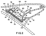
- a first element 10 is provided which includes a lens having a trough portion 12 and a transparent lens portion 14.
- the trough portion 12 comprises a reflective metallized inner surface 16.
- the first element 10 is made from a transparent plastic material which may be, for example, a red polycarbonate.
- the surface 16 may be covered with a reflective metallized material such as aluminum, the lens portion 14 being left transparent by not applying such aluminum thereto.
- the aluminum may be applied to the inner surface 16 by coating, if desired. It should be noted that all of the metallized surfaces described herein comprise a radio frequency absorbing material such as, for example, aluminum, which may be applied by coating.
- the housing of the lamp assembly of the present invention also includes a second element.
- the second element may include a single plastic piece which includes a backing portion and a reflector portion or may be formed from two separate pieces which form a backing portion and a reflector portion, repectively, which are coupled together.
- the second element 18 is formed from two separate pieces.
- One piece is the reflector portion 20 having a reflective metallized surface 22 which faces the metallized surface 16 of the trough portion 12 and the transparent lens portion 14.
- An elongated lamp 24 is mounted to the housing and extends in the trough portion 12.
- first element and the second element are connected and hermetically sealed together by tongue and groove segments at respective edge segments of the housing.
- first element 10 and the second element 18 are connected together by tongue and groove segments 26 and 28.
- first element 10 includes tongue members 30 and 32 at opposite edge segments 34 and 36 of the first element
- second element 18 includes respective mating groove members 38 and 40 at opposite edge segments 42 and 44 of the second element.
- the first and second elements 10, 18 may be connected together in this manner such that the reflective metallized surfaces 16 and 22 form a reflector having a predetermined reflective pattern.
- a sealing adhesive (not shown) may be provided at the tongue and groove interfaces to adhere and hermetically seal together the first element 10 and second element 18.
- elongated lamp 24 has an axis of discharge 46.
- the predetermined reflective pattern lies in a plane perpendicular to the axis of discharge 46 and forms a spiral relative to the axis of discharge.
- the predetermined reflective pattern is described in more detail hereinafter.
- the first element 10 includes a leg portion 48 which extends from the trough portion 12 to the edge segment 36.
- the leg portion 48 has a radio frequency absorbing inner surface such as a metallized inner surface 50 which extends from the metallized surface 16 towards the end of the leg portion 48.
- the second element 18 includes a leg portion 52 which extends from the reflector portion 20 towards the edge segment 44.
- the leg portion 52 has a radio frequency absorbing inner surface such as a metallized inner surface 54 which extends from the metallized surface 22 towards the end of the leg portion.
- the metallized surface 50 faces, and is in close proximity to, the metallized surface 54.
- the second element 18 comprises a separate backing portion 56.
- the reflector portion 20 extends away from the backing portion 56 to form a cavity 58 between the reflector portion 20 and the backing portion.
- a ballast member 60 is mounted in cavity 58.
- cavity 58 may comprise a recess 62 into which a mating ballast member 60 may be inserted.
- Recess 62 may be provided on the backing portion 56, or as depicted in the drawings, on the inner surface of the leg portion 52.
- a radio frequency absorbing surface may be provided at the inner surface of the leg portion 52 around the ballast recess. For example, such area may be provided with a metallized surface. As illustrated in FIG.
- the reflector portion 20 is held in place relative to the backing portion 56 and the lens portion 14 by sandwiching the leg portion 52 extending from the reflector portion 20 between the leg portion 48, extending from the trough portion 12, and an inner surface 64 of the backing portion 56.
- the cavity 58 comprises an inner boundary formed by inner surfaces 66, 68 and 70 of the reflector portion 20, leg portion 52 and backing portion 56, respectively.
- the inner boundary comprises a radio frequency absorbing surface such as an inner boundary metallized surface.
- a portion of inner surface 70 of the backing portion 56 forms a metallized surface 72.
- a conductive member is electrically connected between the inner boundary metallized surface, on the one hand, and the metallized surfaces 50 and 54, on the other. To this end, such conductive member is preferably sandwiched between the metallized surfaces 50 and 54.
- a stainless steel clip 74 is provided.
- Clip 74 includes a first arm 76 and second arm 78 which extends from, and is spring-biassed away from, the first arm.
- the first arm 76 is sandwiched between the metallized surfaces 50 and 54, and the second arm 78 extends into cavity 58 and is spring-biassed into engagement with the inner boundary metallized surface 72.
- Ballast member 60 includes two conductors (not shown) electrically connected to opposite ends of the elongated lamp 24, and a ground conductor 80 electrically and mechanically connected to the inner boundary metallized surface 72 by screw 82.
- the radio frequency absorbing materials formed about the ballast recess 62, on the backing 56 at 72, between leg portions 48, 52 at 50, 54, and on the reflector surface 22 and trough surface 16, may be coupled to the system electrical ground (not shown) to intercept all radio frequency broadcast before transmission through the lamp gap.
- a non-imaging optical set-up which includes a reflector which effectively completely surrounds the elongated lamp 24 so that there is no direct light emanating from the source.
- the visible spectral component of the lamp 24 comprises a maximum upper beam component 84, a maximum lower beam component 86 and a center beam component 88, the center beam component being approximately horizontal.
- Such visible spectral component of lamp 24 escapes from the reflector cavity 90 and through the lamp gap 92 after at least being once reflected.
- the lamp assembly may comprise a lamp 24 which is a low wattage, elongated neon discharge lamp tube which emits light and radio frequency noise.
- a lamp may be a 7 watt, 50 torr neon lamp which is fabricated from a gas filled tube having an inner diameter of 3 mm, an outer diameter of 5 mm and a length which extends in the direction of axis 46 of about 14 inches.
- the pulse rate is 15 kHz.
- Such a low wattage lamp has low heat production.
- the elongated lamp can be cradled by small protuberances extending from the trough portion 12 and the reflector portion 20 which allows both optimum centering of the lamp and close spacing between the lamp and metallized reflective surfaces. Such positioning of the lamp facilitates efficient trapping of all of the light and radio frequency.
- Such a configuration allows efficient radiation of the small level of light produced and good capture of the radio frequency.
- Elements 10 and 18 provide a sealed housing which encloses the lamp tube.
- the lens includes the lens portion 14 and the reflective trough portion 16 which extend approximately the length of lamp 24.
- Trough 16 has a first edge 94 and a second edge 96.
- Reflector portion 20 has an inner edge 98 and an outer edge 100. Inner edge 98 is positioned adjacent the lens along the first edge 94.
- the reflector portion 20 curves across and away from the trough 16 so that the outer edge 100 at least intersects a plane which extends through the first edge 94 and the outer edge while providing no direct line of sight to the trough.
- the large tube 24 is axially centered in trough 16 and is offset from the lens portion 14 and the reflector portion 20.
- the backing portion 56 is sealed to the lens along edges 42 and 44 to enclose the reflector portion 20 and define the cavity 58 which provides a wireway and the ballast recess 62 between the backing portion and the reflector portions.
- the light reflective material of surface 16 is formed on the inner surface of the lens between edges 94 and 96, and the light reflective material of surface 22 is formed between edges 98 and 100.
- metallized surfaces 16 and 22 comprise several individual portions that are relatively aligned for best performance.
- the reflector component formed by metallized surfaces 16 and 22 is composed of four individual surfaces including a first surface 102 which is part of a parabolic cylinder, a second surface 104 which is part of a circular cylinder, and third and fourth surfaces 106 and 108 which are part of a spiral cylinder, or in the alternative, part of an elliptical cylinder.
- break 110 is not depicted in FIGS. 3 to 5.
- elongated lamp 24 may be a neon lamp comprising a gas filled tube 24' having a diameter that is substantially smaller than the length of the tube.
- the diameter of the tube may be as small as, for example, 3 mm (inner diameter) and 5 mm (outer diameter).
- Such a characteristic implies one dimensioned reflector design wherein the reflector components may be obtained by sweeping a line parallel to the axis 46 of the lamp 24 along a composite curve to form a generally spiral pattern in a plane which is perpendicular to axis 46.
- Axis 46 is the axis of the discharge of lamp 24.
- a reflector of the type depicted in FIG. 4 wherein spiral surfaces which are part of a spiral cylinder are utilized.
- metallized surfaces 16 and 22 collectively consist of individual surfaces including a first surface 102 which is part of a parabolic cylinder, a second surface 104 which is part of a circular cylinder and opposes surface 102, and third and fourth surfaces 106' and 108' which are part of a spiral cylinder.
- Surfaces 102, 104, 106' and 108' are connected as depicted in FIG. 5 into one continuous composite curve.
- the focal point of the parabola associated with the surface 102 and the center of curvature of the circle associated with the surface 104 are located within the inner diameter of the glass tube 24'.
- such parabolic focal point and center point of the circular arc is the centerline of the discharge; that is, the axis 46 of lamp 24.
- the spiral surfaces 106' and 108' force the light emitted by lamp 24 not being initially intercepted by parabolic surface 102 or circular surface 104, to escape the reflector cavity 90 via multiple reflections from reflector surfaces.
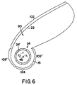
- the embodiment depicted schematically in FIG. 6 is identical to that of FIG. 5 with the exception that spiral-type surfaces 106' and 108' are replaced by surfaces 106'' and 108'' which are part of an elliptical cylinder.
- the elliptical surfaces 106'' and 108'' are aligned so that foci f1 of elliptical surface 106'' coincides with the centerline of the discharge, which as noted is the axis 46 of lamp 24, and the foci f2 of elliptical surface 108'' is displaced vertically above the centerline.
- the elliptical surfaces 106'' and 108'' force the light emitted by lamp 24, not being initially intercepted by parabolic surface 102 or circular surface 104, to escape the reflector cavity 90 via multiple reflections from reflector surfaces.
- FIG. 1 schematically illustrates the lamp assembly of the present invention placed in a spoiler 114 of a vehicle (not shown) to provide a signal lamp for the vehicle.
- the transparent lens portion 14 provides an output window for the light emitted by lamp 24, and in the preferred embodiment such output window will follow the contours of the spoiler 114.
- the lamp assembly may be inserted into a spoiler recess 116 which is configured to effect such a result.
- the lamp assembly of the present invention will comprise reflector components which will be aligned as described herein to achieve the necessary output light distribution complying to automotive signal lighting specifications.
- a lamp assembly wherein the reflector surrounds the tubular neon light source so that there is no direct radiation emitted by the source escaping the reflector cavity.
- the reflective coating, applied to the reflector component is connected to the system electrical ground. That assures that any direct EMR emitted by the source media is effectively absorbed by the conductive reflector coating assuring effective shielding of the EMR component of the emitted spectrum.
- the visible part of the emitted spectrum is reflected by the reflector coating and exits the reflector opening after at least one reflection from the reflector surfaces. The rays from the source emitted towards the parabolic portion of the reflector exit the lamp after one reflection from the reflector surface.
- FIG. 1 shows the light distribution from the lamp ray-trace model according to the present invention employing a neon tube with intensity of 11.7 CD in a direction orthogonal to the axis (centerline) of the source.
- the output light distribution complies with the requirements of FMVSS 108 for CHMSL (center high mounted stop lamp) applications.
- the reflector eliminates the need for any additional EMI shielding element, effectively reducing the cost of the entire assembly.
Landscapes
- Engineering & Computer Science (AREA)
- General Engineering & Computer Science (AREA)
- Non-Portable Lighting Devices Or Systems Thereof (AREA)
- Discharge Lamps And Accessories Thereof (AREA)
Applications Claiming Priority (2)
| Application Number | Priority Date | Filing Date | Title |
|---|---|---|---|
| US08/803,930 US5993034A (en) | 1997-02-21 | 1997-02-21 | Lamp reflector for use with gaseous discharge lighting |
| US803930 | 1997-02-21 |
Publications (2)
| Publication Number | Publication Date |
|---|---|
| EP0860655A2 true EP0860655A2 (fr) | 1998-08-26 |
| EP0860655A3 EP0860655A3 (fr) | 2000-03-22 |
Family
ID=25187787
Family Applications (1)
| Application Number | Title | Priority Date | Filing Date |
|---|---|---|---|
| EP98102941A Withdrawn EP0860655A3 (fr) | 1997-02-21 | 1998-02-20 | Réflecteur pour lampe à décharge |
Country Status (4)
| Country | Link |
|---|---|
| US (1) | US5993034A (fr) |
| EP (1) | EP0860655A3 (fr) |
| JP (1) | JP4034869B2 (fr) |
| CA (1) | CA2225769C (fr) |
Cited By (4)
| Publication number | Priority date | Publication date | Assignee | Title |
|---|---|---|---|---|
| GB2347995A (en) * | 1999-02-23 | 2000-09-20 | Koito Mfg Co Ltd | Vehicle lamp with a discharge bulb and a reflector with shielding of electromagnetic waves |
| WO2000071927A1 (fr) * | 1999-05-20 | 2000-11-30 | Zumtobel Staff Gmbh | Dispositif d'eclairage |
| EP1643538A3 (fr) * | 2004-09-29 | 2008-02-13 | Patent-Treuhand-Gesellschaft für elektrische Glühlampen mbH | Lampe à décharge à barrière dielectrique avec blindage électrique |
| US7573201B2 (en) | 2004-09-29 | 2009-08-11 | Osram Gesellschaft Mit Beschraenkter Haftung | Dielectric barrier discharge lamp having pluggable electrodes |
Families Citing this family (4)
| Publication number | Priority date | Publication date | Assignee | Title |
|---|---|---|---|---|
| US7052074B2 (en) * | 2003-10-03 | 2006-05-30 | All Sales Manufacturing, Inc. | Angularly adjustable illuminated spoiler |
| US7950836B2 (en) * | 2008-05-09 | 2011-05-31 | Osram Sylvania Inc. | EMI controlled integral HID reflector lamp |
| US20090289553A1 (en) * | 2008-05-23 | 2009-11-26 | Osram Sylvania, Inc. | Integrated ceramic metal halide high frequency ballast assembly |
| US8581482B2 (en) * | 2009-04-30 | 2013-11-12 | Osram Sylvania Inc. | PAR lamp and method of making same |
Family Cites Families (16)
| Publication number | Priority date | Publication date | Assignee | Title |
|---|---|---|---|---|
| US1826927A (en) * | 1928-12-05 | 1931-10-13 | Holophane Co Inc | Light projector |
| US1913517A (en) * | 1929-04-24 | 1933-06-13 | Harold E Smith | Light projection |
| US2316546A (en) * | 1940-05-31 | 1943-04-13 | Rambusch Decorating Company | Lighting apparatus |
| US2632842A (en) * | 1949-08-27 | 1953-03-24 | James L Grupen | Sealed headlight having auxiliary reflector |
| FR1072019A (fr) * | 1953-01-07 | 1954-09-07 | Perfectionnements aux lampes à décharge | |
| US2740103A (en) * | 1953-09-11 | 1956-03-27 | Fed Sign And Signal Corp | Signal lamp |
| US3588492A (en) * | 1968-10-01 | 1971-06-28 | Gen Motors Corp | Rectangular vehicle headlamp with collimating discs |
| AR214983A1 (es) * | 1976-10-28 | 1979-08-31 | Urbametal Soc Responsabilidad | Proyector luminoso |
| US4349866A (en) * | 1980-05-27 | 1982-09-14 | General Signal Corporation | Light reflection system with asymmetric reflector assembly |
| US4587601A (en) * | 1981-07-23 | 1986-05-06 | Collins Dynamics, Inc. | Combined flood and spot light incorporating a reflector member of circular and parabolic longitudinal cross section |
| US4947292A (en) * | 1988-11-08 | 1990-08-07 | Vlah John A | Lighting system |
| GB8917055D0 (en) * | 1989-07-26 | 1989-09-13 | Light Years Ahead Ltd | Space lighting fitting |
| US5347435A (en) * | 1992-12-22 | 1994-09-13 | Hughes Aircraft Company | Linear lamp holographic trapped beam center high mounted stoplight |
| US5471371A (en) * | 1993-01-08 | 1995-11-28 | Ford Motor Company | High efficiency illuminator |
| FR2717982B1 (fr) * | 1994-03-24 | 1996-05-15 | Valeo Vision | Dispositif de blindage électromagnétique de systèmes d'éclairage et/ou de signalisation de véhicule du type lampe à décharge tubulaire. |
| US5618102A (en) * | 1995-06-07 | 1997-04-08 | Adac Plastics, Inc. | Plasma discharge lamp |
-
1997
- 1997-02-21 US US08/803,930 patent/US5993034A/en not_active Expired - Lifetime
- 1997-12-23 CA CA002225769A patent/CA2225769C/fr not_active Expired - Lifetime
-
1998
- 1998-02-18 JP JP05126398A patent/JP4034869B2/ja not_active Expired - Fee Related
- 1998-02-20 EP EP98102941A patent/EP0860655A3/fr not_active Withdrawn
Cited By (7)
| Publication number | Priority date | Publication date | Assignee | Title |
|---|---|---|---|---|
| GB2347995A (en) * | 1999-02-23 | 2000-09-20 | Koito Mfg Co Ltd | Vehicle lamp with a discharge bulb and a reflector with shielding of electromagnetic waves |
| GB2347995B (en) * | 1999-02-23 | 2001-10-03 | Koito Mfg Co Ltd | Vehicle lamp with discharge bulb |
| US6309089B1 (en) | 1999-02-23 | 2001-10-30 | Koito Manufacturing Co., Ltd. | Vehicle lamp with discharge bulb, electrically-conductive cover, and reflector having electrically-conductive film on reflector surface |
| WO2000071927A1 (fr) * | 1999-05-20 | 2000-11-30 | Zumtobel Staff Gmbh | Dispositif d'eclairage |
| US6945670B2 (en) | 1999-05-20 | 2005-09-20 | Zumtobel Staff Gmbh | Luminaire |
| EP1643538A3 (fr) * | 2004-09-29 | 2008-02-13 | Patent-Treuhand-Gesellschaft für elektrische Glühlampen mbH | Lampe à décharge à barrière dielectrique avec blindage électrique |
| US7573201B2 (en) | 2004-09-29 | 2009-08-11 | Osram Gesellschaft Mit Beschraenkter Haftung | Dielectric barrier discharge lamp having pluggable electrodes |
Also Published As
| Publication number | Publication date |
|---|---|
| US5993034A (en) | 1999-11-30 |
| CA2225769C (fr) | 2007-01-30 |
| JP4034869B2 (ja) | 2008-01-16 |
| JPH10241427A (ja) | 1998-09-11 |
| CA2225769A1 (fr) | 1998-08-21 |
| EP0860655A3 (fr) | 2000-03-22 |
Similar Documents
| Publication | Publication Date | Title |
|---|---|---|
| CN1184432C (zh) | 用于紫外线灯系统的反射器 | |
| US3115309A (en) | Aperture fluorescent lamp | |
| US5130904A (en) | Automotive headlamp waving no ultraviolet output | |
| US5618102A (en) | Plasma discharge lamp | |
| US20050094393A1 (en) | Light assembly | |
| US5993034A (en) | Lamp reflector for use with gaseous discharge lighting | |
| CN1322034A (zh) | 微波天线 | |
| EP0775280A1 (fr) | Systeme de signalisation | |
| US6270241B1 (en) | Unit comprising at least one headlight and at least one indicator light, for a motor vehicle | |
| US5610472A (en) | Lamp assembly with resilient connector for locating and cushioning neon lamp | |
| US4985814A (en) | Warning light with quadruple reflective surfaces | |
| US6153982A (en) | Discharge lamp and lighting system having a discharge lamp | |
| GB2223300A (en) | Vehicle head lamp | |
| JP3162290B2 (ja) | 放電バルブを有する車両用灯具 | |
| EP0176103A1 (fr) | Projecteur d'automobile | |
| EP0773137A2 (fr) | Lampe néon avec écran antiparasite | |
| US4092705A (en) | Method of illuminating an object and a device for carrying out the method | |
| WO1999018597A1 (fr) | Tube fluorescent presentant deux couches de diffusion diametralement opposees | |
| US3801808A (en) | Light source with rf interference shield | |
| US6464372B1 (en) | Lamp device and assembly | |
| WO2002011171A1 (fr) | Lampe a fenetre, boitier de lampe a fenetre et ensemble de lampe a fenetre | |
| MXPA02003390A (es) | Aparato de iluminacion que utiliza microonda. | |
| JP3162300B2 (ja) | 放電バルブを有する車両用灯具 | |
| JPH1173928A5 (fr) | ||
| JPH04160701A (ja) | 自動車用ヘッドランプ |
Legal Events
| Date | Code | Title | Description |
|---|---|---|---|
| PUAI | Public reference made under article 153(3) epc to a published international application that has entered the european phase |
Free format text: ORIGINAL CODE: 0009012 |
|
| 17P | Request for examination filed |
Effective date: 19980318 |
|
| AK | Designated contracting states |
Kind code of ref document: A2 Designated state(s): BE DE FR GB IT NL |
|
| AX | Request for extension of the european patent |
Free format text: AL;LT;LV;MK;RO;SI |
|
| PUAL | Search report despatched |
Free format text: ORIGINAL CODE: 0009013 |
|
| AK | Designated contracting states |
Kind code of ref document: A3 Designated state(s): AT BE CH DE DK ES FI FR GB GR IE IT LI LU MC NL PT SE |
|
| AX | Request for extension of the european patent |
Free format text: AL;LT;LV;MK;RO;SI |
|
| RIC1 | Information provided on ipc code assigned before grant |
Free format text: 7F 21V 25/00 A, 7F 21V 7/12 B, 7B 60Q 1/30 B |
|
| AKX | Designation fees paid |
Free format text: BE DE FR GB IT NL |
|
| 17Q | First examination report despatched |
Effective date: 20020517 |
|
| 17Q | First examination report despatched |
Effective date: 20020517 |
|
| STAA | Information on the status of an ep patent application or granted ep patent |
Free format text: STATUS: THE APPLICATION HAS BEEN WITHDRAWN |
|
| 18W | Application withdrawn |
Effective date: 20070526 |