EP0860665A1 - Ausbaufähige Heizung - Google Patents
Ausbaufähige Heizung Download PDFInfo
- Publication number
- EP0860665A1 EP0860665A1 EP98400323A EP98400323A EP0860665A1 EP 0860665 A1 EP0860665 A1 EP 0860665A1 EP 98400323 A EP98400323 A EP 98400323A EP 98400323 A EP98400323 A EP 98400323A EP 0860665 A1 EP0860665 A1 EP 0860665A1
- Authority
- EP
- European Patent Office
- Prior art keywords
- cell
- boiler
- stove
- door
- ashtray
- Prior art date
- Legal status (The legal status is an assumption and is not a legal conclusion. Google has not performed a legal analysis and makes no representation as to the accuracy of the status listed.)
- Granted
Links
- 238000010438 heat treatment Methods 0.000 title claims abstract description 18
- 239000012530 fluid Substances 0.000 claims abstract description 10
- 239000002023 wood Substances 0.000 claims abstract description 9
- 239000007788 liquid Substances 0.000 claims abstract description 8
- 239000003245 coal Substances 0.000 claims abstract description 7
- 239000000446 fuel Substances 0.000 claims description 15
- 239000004449 solid propellant Substances 0.000 claims description 8
- 239000000779 smoke Substances 0.000 claims description 4
- XLYOFNOQVPJJNP-UHFFFAOYSA-N water Substances O XLYOFNOQVPJJNP-UHFFFAOYSA-N 0.000 claims description 4
- 238000002485 combustion reaction Methods 0.000 claims description 3
- 230000001105 regulatory effect Effects 0.000 claims description 2
- 230000000717 retained effect Effects 0.000 claims description 2
- 230000000149 penetrating effect Effects 0.000 claims 1
- 230000001737 promoting effect Effects 0.000 claims 1
- 239000003610 charcoal Substances 0.000 description 2
- 239000000295 fuel oil Substances 0.000 description 2
- 238000009434 installation Methods 0.000 description 2
- 235000002918 Fraxinus excelsior Nutrition 0.000 description 1
- 230000003044 adaptive effect Effects 0.000 description 1
- 239000002956 ash Substances 0.000 description 1
- 238000005452 bending Methods 0.000 description 1
- 239000002737 fuel gas Substances 0.000 description 1
- 239000003517 fume Substances 0.000 description 1
- 238000005065 mining Methods 0.000 description 1
- 239000000203 mixture Substances 0.000 description 1
- 239000003921 oil Substances 0.000 description 1
- 239000002245 particle Substances 0.000 description 1
- 238000007789 sealing Methods 0.000 description 1
- 238000000638 solvent extraction Methods 0.000 description 1
- 230000009466 transformation Effects 0.000 description 1
Images





Classifications
-
- F—MECHANICAL ENGINEERING; LIGHTING; HEATING; WEAPONS; BLASTING
- F24—HEATING; RANGES; VENTILATING
- F24H—FLUID HEATERS, e.g. WATER OR AIR HEATERS, HAVING HEAT-GENERATING MEANS, e.g. HEAT PUMPS, IN GENERAL
- F24H1/00—Water heaters, e.g. boilers, continuous-flow heaters or water-storage heaters
- F24H1/22—Water heaters other than continuous-flow or water-storage heaters, e.g. water heaters for central heating
- F24H1/24—Water heaters other than continuous-flow or water-storage heaters, e.g. water heaters for central heating with water mantle surrounding the combustion chamber or chambers
- F24H1/30—Water heaters other than continuous-flow or water-storage heaters, e.g. water heaters for central heating with water mantle surrounding the combustion chamber or chambers the water mantle being built up from sections
- F24H1/32—Water heaters other than continuous-flow or water-storage heaters, e.g. water heaters for central heating with water mantle surrounding the combustion chamber or chambers the water mantle being built up from sections with vertical sections arranged side by side
-
- F—MECHANICAL ENGINEERING; LIGHTING; HEATING; WEAPONS; BLASTING
- F24—HEATING; RANGES; VENTILATING
- F24H—FLUID HEATERS, e.g. WATER OR AIR HEATERS, HAVING HEAT-GENERATING MEANS, e.g. HEAT PUMPS, IN GENERAL
- F24H1/00—Water heaters, e.g. boilers, continuous-flow heaters or water-storage heaters
Definitions
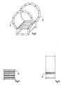
- the present invention relates to a scalable heating system having the particularity of having several different applications. (See fig. 1 and fig. 2).
- the basic function being a stove, it can be converted into a boiler intended for heat and circulate various fluids (Water, oil) to heating elements such as radiators or any other radiating system.
- This heating system can use either solid fuels, such as coal, wood, or liquid fuels such as fuel oil or gaseous fuels.
- This invention overcomes the above-mentioned drawbacks insofar as the system accepts various types of fuel through very adaptive simple.
- This heating system in its basic function, consists of an element standard, unique and monobloc called "cell” as shown in perspective fig. 3.
- This specifically shaped cell encloses the hearth where the fuel is consumed.
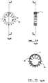
- This single cell is partitioned by a front face (fig. 6), fitted with a door main (fig. 1.1 and fig. 2.2) and a rear face (fig. 7) in which is arranged, among other things, an opening intended to receive the evacuation conduit for smoke (fig.7.3) and pre-equipped to receive a boiler (fig.8, fig.9 and fig.10) in the case of use in boiler mode.
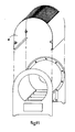
- the assembly is capped by a cover as shown in FIG. 11.4.
- the front face (fig. 6) is fitted with a movable main door (fig. 1.1) mounted on side hinges. This opening allows the introduction of fuel.
- a single cell thus equipped corresponds to the minimum of power.
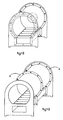
- the increase of this heating power can be achieved by adding one or more cells arranged after the first (fig. 13)
- This assembly is carried out, after dismantling of the rear face, by bolting a second cell behind the first (fig. 14 and fig. 15).
- the basic monobloc cell has at each of its ends of pierced square fins (n ° 5).
- the triple role of these angle fins is to ensure the rigidity of the assembly, during assembly (fig. 13), so that that the bending force exerted on the assembly is equivalent to that exercising on a single cell since each of them rests on the ground, it is also to seal the assembly and it is also to spare, after fixing the hood, a space in which the circulation of outside air is forced (fig. 11).
- Transformation of the system to switch from solid fuel (coal, wood) to a liquid fuel (fuel) or gaseous, is carried out by replacing the door main of the front face (fig. 1.1) by another (fig. 2.2) fitted with a burner suitable using liquid or gaseous fuel.
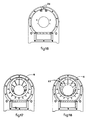
- a boiler (fig.8, fig.9 and fig.10) is fixed on the rear face of the assembly (fig.17.6).
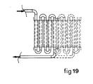
- the cold fluid enters the coil (fig. 19) located in the lower part of the cell. After having thus passed through this coil, it enters the boiler (fig. 9.7 and fig.10.7) in order to be brought to the desired temperature. The fluid thus heated is then ready to irrigate the elements of use such as radiators and water tank hot.
- the volume of the boiler located on the rear side to obtain the desired power.
- the present invention in its basic composition and as drawn in its together (fig. 1 and fig.2), is composed of:
- a main cell (fig. 3).
- Ducts (fig.4.8 and fig.5.8) intended to accommodate the coil in which the fluid passes into the "boiler" configuration.
- the front face (fig. 6) has the function of sealing off the face front of the cell while receiving either a so-called main door, glazed or full (fig. 1.1) in the case of solid fuel (wood, charcoal), i.e. a door main pledge of the burner in the case of fluid or gaseous fuel (fig. 2.2).
- the front panel also receives the secondary door giving access (fig. 1.9) to the ashtray (fig. 20, fig. 21 and fig. 22).
- the front side of the ashtray receives the wheel draw (fig.20.10, fig.21.10 and fig.22.10). It should be noted that in the event of functioning by means of a liquid or gaseous fuel, the function of said wheel becomes irrelevant and it remains permanently closed.
- This ashtray receives a selective grid (fig. 21.11 and fig. 22.11), arranged longitudinally with respect to the axis of the cell, intended to stop, on the one hand, embers still likely to radiate effectively in the cell's hearth and on the other hand, those whose combustion is completely carried out and which can go through said grid to go into the bottom of the ashtray provided for this purpose.
- a selective grid fig. 21.11 and fig. 22.11
- the ashtray which equips each cell is provided along its length with hollow ducts with diamond-shaped section (fig. 21.12 and fig. 22.12). It also has anterior side (fig.20.13, fig.21.13 and fig.22.13) and a posterior side (fig. 21.14 and fig. 22.14).
- the front side receives a wheel which controls two separate openings: one of these openings gives access to the primary air which enters the fireplace (fig.20.15 and fig.21.15), the other opens the access to the primary air to the hollow ducts (fig. 20.16 and fig. 21.16).
- These hollow conduits are arranged parallel and longitudinally so as to that two opposite edges determine a vertical plane.
- the upper walls are full, allowing the ashes to fall to the bottom of the ashtray without clog the duct.
- the lower walls are drilled (fig. 21.17) so that that the primary air can penetrate and favor the combustion of particles not totally consumed retained on the ashtray grate (fig. 21.11 and fig. 22.11).
- the ashtray is designed so as to fit in series and end to end with the ashtray of another cell.
- the rear face (fig. 7) also has the task of partitioning in a way seals the rear face of the cell while receiving the exhaust fumes via a baffle (fig. 23 and fig. 24) imposing the passage of smoke at a point precise (fig. 24.18) where the ducted, heated secondary air arrives (fig. 24.20) which causes them to re-burn.
- the intake of this secondary air is regulated by one or two taps, having the same functions, (fig. 24.19) fixed on the rear face of the cell.
- the rear face (fig. 25) of the cell receives a support (fig. 26.21) allowing the installation of said baffle (fig. 27.22).
- This circular-shaped boiler including the inner fins (fig. 8.24) and external (fig. 8.25) are designed to promote energy capture thermal function, has the function of receiving the fluid intended to be conveyed in the radiating elements.
- the plugs (fig. 16.23) are unscrewed to allow the elements (fig.9.7) of the boiler to be inserted.
- Figure 18 shows the assembly of the boiler (fig. 8) as well as the baffle (fig. 18.22).
Landscapes
- Engineering & Computer Science (AREA)
- Physics & Mathematics (AREA)
- Thermal Sciences (AREA)
- Chemical & Material Sciences (AREA)
- Combustion & Propulsion (AREA)
- Mechanical Engineering (AREA)
- General Engineering & Computer Science (AREA)
- Perforating, Stamping-Out Or Severing By Means Other Than Cutting (AREA)
- Resistance Heating (AREA)
- Earth Drilling (AREA)
- Solid-Fuel Combustion (AREA)
- Cookers (AREA)
Applications Claiming Priority (2)
| Application Number | Priority Date | Filing Date | Title |
|---|---|---|---|
| FR9702001 | 1997-02-20 | ||
| FR9702001A FR2745371B1 (fr) | 1996-02-22 | 1997-02-20 | Concept de chauffage evolutif |
Publications (2)
| Publication Number | Publication Date |
|---|---|
| EP0860665A1 true EP0860665A1 (de) | 1998-08-26 |
| EP0860665B1 EP0860665B1 (de) | 2000-08-16 |
Family
ID=9503957
Family Applications (1)
| Application Number | Title | Priority Date | Filing Date |
|---|---|---|---|
| EP98400323A Expired - Lifetime EP0860665B1 (de) | 1997-02-20 | 1998-02-12 | Ausbaufähige Heizung |
Country Status (3)
| Country | Link |
|---|---|
| EP (1) | EP0860665B1 (de) |
| AT (1) | ATE195586T1 (de) |
| DE (1) | DE69800253T2 (de) |
Citations (2)
| Publication number | Priority date | Publication date | Assignee | Title |
|---|---|---|---|---|
| CH492178A (de) * | 1968-05-21 | 1970-06-15 | Zent Ag | Gliederheizkessel |
| FR2590969A1 (fr) * | 1985-11-29 | 1987-06-05 | Roca Radiadores | Chaudiere de chauffage central |
-
1998
- 1998-02-12 DE DE69800253T patent/DE69800253T2/de not_active Expired - Lifetime
- 1998-02-12 AT AT98400323T patent/ATE195586T1/de not_active IP Right Cessation
- 1998-02-12 EP EP98400323A patent/EP0860665B1/de not_active Expired - Lifetime
Patent Citations (2)
| Publication number | Priority date | Publication date | Assignee | Title |
|---|---|---|---|---|
| CH492178A (de) * | 1968-05-21 | 1970-06-15 | Zent Ag | Gliederheizkessel |
| FR2590969A1 (fr) * | 1985-11-29 | 1987-06-05 | Roca Radiadores | Chaudiere de chauffage central |
Also Published As
| Publication number | Publication date |
|---|---|
| DE69800253D1 (de) | 2000-09-21 |
| DE69800253T2 (de) | 2001-10-18 |
| ATE195586T1 (de) | 2000-09-15 |
| EP0860665B1 (de) | 2000-08-16 |
Similar Documents
| Publication | Publication Date | Title |
|---|---|---|
| US7954438B2 (en) | Wood fired boiler | |
| FR2472141A1 (fr) | Poele destine notamment au camping, au caravaning et au nautisme | |
| WO2020249906A4 (fr) | Ensemble a boitier thermiquement controle, pour cellules electriques | |
| FR3013422B1 (fr) | Poele a granules et son procede de fonctionnement | |
| EP0860665B1 (de) | Ausbaufähige Heizung | |
| FR2745371A1 (fr) | Concept de chauffage evolutif | |
| KR101622275B1 (ko) | 컨테이너 바닥에 구비되는 조립형 구들보일러 | |
| EP1695010A1 (de) | Heiz- und luftklimatisierungsvorrichtung | |
| US6123064A (en) | Evolving heating concept | |
| US10371413B2 (en) | Boiler with access to heat exchangers | |
| CH621618A5 (en) | Wood-fired heating apparatus | |
| EP0034136B1 (de) | Raumheizungsanlagen | |
| FR2461893A1 (fr) | Generateur d'eau chaude, notamment chaudiere de chauffage central | |
| CA2926064C (en) | Boiler with access to heat exchangers | |
| KR100759037B1 (ko) | 벽난로 | |
| CA3034157C (en) | Boiler with access to heat exchangers | |
| FR2580785A1 (fr) | Avant-foyer pour bruler des combustibles solides | |
| KR101920568B1 (ko) | 난방기용 포터블 발전기 | |
| KR20190030448A (ko) | 펠릿공급장치 | |
| EP0883782B1 (de) | Heizgerät | |
| FR2881814A1 (fr) | Equipement pour cheminee | |
| CH184576A (fr) | Chaudière en fonte à combustible solide avec installation pour la transformer en une chaudière à combustible liquide ou gazeux. | |
| BE1009908A6 (fr) | Dispositif de combustion et de postcombustion permanentes stabilisees pour combustibles solides, liquides ou gazeux. | |
| FR2508607A1 (fr) | Chaudiere de chauffage central a paille ou bois | |
| BE404342A (de) |
Legal Events
| Date | Code | Title | Description |
|---|---|---|---|
| PUAI | Public reference made under article 153(3) epc to a published international application that has entered the european phase |
Free format text: ORIGINAL CODE: 0009012 |
|
| AK | Designated contracting states |
Kind code of ref document: A1 Designated state(s): AT BE CH DE DK ES FI GB IE IT LI LU NL |
|
| AX | Request for extension of the european patent |
Free format text: AL;LT;LV;MK;RO;SI |
|
| 17P | Request for examination filed |
Effective date: 19990218 |
|
| AKX | Designation fees paid |
Free format text: AT BE CH LI |
|
| RBV | Designated contracting states (corrected) |
Designated state(s): AT BE CH LI |
|
| REG | Reference to a national code |
Ref country code: DE Ref legal event code: 8566 |
|
| RBV | Designated contracting states (corrected) |
Designated state(s): AT BE CH DE DK ES FI GB IE IT LI LU NL |
|
| GRAG | Despatch of communication of intention to grant |
Free format text: ORIGINAL CODE: EPIDOS AGRA |
|
| 17Q | First examination report despatched |
Effective date: 19990906 |
|
| GRAG | Despatch of communication of intention to grant |
Free format text: ORIGINAL CODE: EPIDOS AGRA |
|
| GRAG | Despatch of communication of intention to grant |
Free format text: ORIGINAL CODE: EPIDOS AGRA |
|
| GRAH | Despatch of communication of intention to grant a patent |
Free format text: ORIGINAL CODE: EPIDOS IGRA |
|
| GRAH | Despatch of communication of intention to grant a patent |
Free format text: ORIGINAL CODE: EPIDOS IGRA |
|
| GRAA | (expected) grant |
Free format text: ORIGINAL CODE: 0009210 |
|
| AK | Designated contracting states |
Kind code of ref document: B1 Designated state(s): AT BE CH DE DK ES FI GB IE IT LI LU NL |
|
| PG25 | Lapsed in a contracting state [announced via postgrant information from national office to epo] |
Ref country code: IT Free format text: LAPSE BECAUSE OF FAILURE TO SUBMIT A TRANSLATION OF THE DESCRIPTION OR TO PAY THE FEE WITHIN THE PRESCRIBED TIME-LIMIT;WARNING: LAPSES OF ITALIAN PATENTS WITH EFFECTIVE DATE BEFORE 2007 MAY HAVE OCCURRED AT ANY TIME BEFORE 2007. THE CORRECT EFFECTIVE DATE MAY BE DIFFERENT FROM THE ONE RECORDED. Effective date: 20000816 Ref country code: FI Free format text: LAPSE BECAUSE OF FAILURE TO SUBMIT A TRANSLATION OF THE DESCRIPTION OR TO PAY THE FEE WITHIN THE PRESCRIBED TIME-LIMIT Effective date: 20000816 Ref country code: ES Free format text: THE PATENT HAS BEEN ANNULLED BY A DECISION OF A NATIONAL AUTHORITY Effective date: 20000816 |
|
| REF | Corresponds to: |
Ref document number: 195586 Country of ref document: AT Date of ref document: 20000915 Kind code of ref document: T |
|
| REG | Reference to a national code |
Ref country code: CH Ref legal event code: EP |
|
| REG | Reference to a national code |
Ref country code: IE Ref legal event code: FG4D Free format text: FRENCH |
|
| REF | Corresponds to: |
Ref document number: 69800253 Country of ref document: DE Date of ref document: 20000921 |
|
| PG25 | Lapsed in a contracting state [announced via postgrant information from national office to epo] |
Ref country code: DK Free format text: LAPSE BECAUSE OF FAILURE TO SUBMIT A TRANSLATION OF THE DESCRIPTION OR TO PAY THE FEE WITHIN THE PRESCRIBED TIME-LIMIT Effective date: 20001116 |
|
| GBT | Gb: translation of ep patent filed (gb section 77(6)(a)/1977) |
Effective date: 20001120 |
|
| PG25 | Lapsed in a contracting state [announced via postgrant information from national office to epo] |
Ref country code: LU Free format text: LAPSE BECAUSE OF NON-PAYMENT OF DUE FEES Effective date: 20010212 Ref country code: AT Free format text: LAPSE BECAUSE OF NON-PAYMENT OF DUE FEES Effective date: 20010212 |
|
| PG25 | Lapsed in a contracting state [announced via postgrant information from national office to epo] |
Ref country code: BE Free format text: LAPSE BECAUSE OF NON-PAYMENT OF DUE FEES Effective date: 20010228 |
|
| PG25 | Lapsed in a contracting state [announced via postgrant information from national office to epo] |
Ref country code: IE Free format text: LAPSE BECAUSE OF NON-PAYMENT OF DUE FEES Effective date: 20010419 |
|
| REG | Reference to a national code |
Ref country code: IE Ref legal event code: FD4D |
|
| PLBE | No opposition filed within time limit |
Free format text: ORIGINAL CODE: 0009261 |
|
| STAA | Information on the status of an ep patent application or granted ep patent |
Free format text: STATUS: NO OPPOSITION FILED WITHIN TIME LIMIT |
|
| 26N | No opposition filed | ||
| BERE | Be: lapsed |
Owner name: JACQUET PATRICE Effective date: 20010228 |
|
| REG | Reference to a national code |
Ref country code: GB Ref legal event code: IF02 |
|
| PG25 | Lapsed in a contracting state [announced via postgrant information from national office to epo] |
Ref country code: LI Free format text: LAPSE BECAUSE OF NON-PAYMENT OF DUE FEES Effective date: 20020228 Ref country code: CH Free format text: LAPSE BECAUSE OF NON-PAYMENT OF DUE FEES Effective date: 20020228 |
|
| PG25 | Lapsed in a contracting state [announced via postgrant information from national office to epo] |
Ref country code: NL Free format text: LAPSE BECAUSE OF NON-PAYMENT OF DUE FEES Effective date: 20020901 |
|
| REG | Reference to a national code |
Ref country code: CH Ref legal event code: PL |
|
| NLV4 | Nl: lapsed or anulled due to non-payment of the annual fee |
Effective date: 20020901 |
|
| PG25 | Lapsed in a contracting state [announced via postgrant information from national office to epo] |
Ref country code: DE Free format text: LAPSE BECAUSE OF NON-PAYMENT OF DUE FEES Effective date: 20100901 |
|
| PGFP | Annual fee paid to national office [announced via postgrant information from national office to epo] |
Ref country code: DE Payment date: 20110324 Year of fee payment: 14 |
|
| PGFP | Annual fee paid to national office [announced via postgrant information from national office to epo] |
Ref country code: GB Payment date: 20110216 Year of fee payment: 14 |
|
| GBPC | Gb: european patent ceased through non-payment of renewal fee |
Effective date: 20120212 |
|
| REG | Reference to a national code |
Ref country code: DE Ref legal event code: R119 Ref document number: 69800253 Country of ref document: DE Effective date: 20120901 |
|
| PG25 | Lapsed in a contracting state [announced via postgrant information from national office to epo] |
Ref country code: GB Free format text: LAPSE BECAUSE OF NON-PAYMENT OF DUE FEES Effective date: 20120212 |
|
| PG25 | Lapsed in a contracting state [announced via postgrant information from national office to epo] |
Ref country code: DE Free format text: LAPSE BECAUSE OF NON-PAYMENT OF DUE FEES Effective date: 20120901 |