EP0883782B1 - Heizgerät - Google Patents
Heizgerät Download PDFInfo
- Publication number
- EP0883782B1 EP0883782B1 EP97903161A EP97903161A EP0883782B1 EP 0883782 B1 EP0883782 B1 EP 0883782B1 EP 97903161 A EP97903161 A EP 97903161A EP 97903161 A EP97903161 A EP 97903161A EP 0883782 B1 EP0883782 B1 EP 0883782B1
- Authority
- EP
- European Patent Office
- Prior art keywords
- heating device
- intermediary part
- opening
- burnt
- housing
- Prior art date
- Legal status (The legal status is an assumption and is not a legal conclusion. Google has not performed a legal analysis and makes no representation as to the accuracy of the status listed.)
- Expired - Lifetime
Links
- 238000010438 heat treatment Methods 0.000 title claims abstract description 34
- 239000000446 fuel Substances 0.000 claims abstract description 16
- 238000004891 communication Methods 0.000 claims abstract description 7
- 239000007789 gas Substances 0.000 claims description 44
- 238000002309 gasification Methods 0.000 claims description 7
- 239000007788 liquid Substances 0.000 claims description 7
- 238000011084 recovery Methods 0.000 claims description 6
- 239000002023 wood Substances 0.000 claims description 6
- 239000004449 solid propellant Substances 0.000 claims description 5
- 238000004140 cleaning Methods 0.000 claims description 4
- 239000003245 coal Substances 0.000 claims description 4
- 239000000779 smoke Substances 0.000 claims description 4
- 230000008020 evaporation Effects 0.000 claims description 3
- 238000001704 evaporation Methods 0.000 claims description 3
- 239000002131 composite material Substances 0.000 claims description 2
- XEEYBQQBJWHFJM-UHFFFAOYSA-N Iron Chemical compound [Fe] XEEYBQQBJWHFJM-UHFFFAOYSA-N 0.000 claims 4
- 238000007599 discharging Methods 0.000 claims 2
- 229910052742 iron Inorganic materials 0.000 claims 2
- 230000001105 regulatory effect Effects 0.000 claims 1
- 229910052572 stoneware Inorganic materials 0.000 claims 1
- 239000003546 flue gas Substances 0.000 abstract description 5
- UGFAIRIUMAVXCW-UHFFFAOYSA-N Carbon monoxide Chemical compound [O+]#[C-] UGFAIRIUMAVXCW-UHFFFAOYSA-N 0.000 abstract description 4
- 238000007789 sealing Methods 0.000 abstract 1
- 125000006850 spacer group Chemical group 0.000 description 5
- 238000002485 combustion reaction Methods 0.000 description 4
- 239000003921 oil Substances 0.000 description 3
- 238000003860 storage Methods 0.000 description 3
- 229910001018 Cast iron Inorganic materials 0.000 description 2
- 230000002093 peripheral effect Effects 0.000 description 2
- 208000031968 Cadaver Diseases 0.000 description 1
- 229910000831 Steel Inorganic materials 0.000 description 1
- 240000008042 Zea mays Species 0.000 description 1
- 239000003610 charcoal Substances 0.000 description 1
- 238000010276 construction Methods 0.000 description 1
- 229910052571 earthenware Inorganic materials 0.000 description 1
- 230000000694 effects Effects 0.000 description 1
- 239000012634 fragment Substances 0.000 description 1
- 239000000295 fuel oil Substances 0.000 description 1
- 206010022000 influenza Diseases 0.000 description 1
- 238000004519 manufacturing process Methods 0.000 description 1
- 239000000463 material Substances 0.000 description 1
- 238000000034 method Methods 0.000 description 1
- 238000012986 modification Methods 0.000 description 1
- 230000004048 modification Effects 0.000 description 1
- 239000007800 oxidant agent Substances 0.000 description 1
- 230000001737 promoting effect Effects 0.000 description 1
- 239000010959 steel Substances 0.000 description 1
Images

Classifications
-
- F—MECHANICAL ENGINEERING; LIGHTING; HEATING; WEAPONS; BLASTING
- F24—HEATING; RANGES; VENTILATING
- F24B—DOMESTIC STOVES OR RANGES FOR SOLID FUELS; IMPLEMENTS FOR USE IN CONNECTION WITH STOVES OR RANGES
- F24B1/00—Stoves or ranges
- F24B1/02—Closed stoves
- F24B1/022—Closed stoves easily collapsible or easily removable
-
- F—MECHANICAL ENGINEERING; LIGHTING; HEATING; WEAPONS; BLASTING
- F24—HEATING; RANGES; VENTILATING
- F24C—DOMESTIC STOVES OR RANGES ; DETAILS OF DOMESTIC STOVES OR RANGES, OF GENERAL APPLICATION
- F24C15/00—Details
- F24C15/001—Details arrangements for discharging combustion gases
Definitions
- the present invention relates to a heater, comprising a heater formed of an assembly of several walls among which a rear wall, delimited by an edge, closes the rear heating element, one outlet for gases burned, and possibly a passage, which is provided in the rear wall and in which an inlet is arranged of air.
- any healthy space heater also requires the supply of combustion air and a burnt gas outlet.
- GB-1-1151741 describes a device heating for solid fuel which aims to regulate the combustion by means of an air supply, controlled in the solid fuel.
- the heater described in this document consists of an assembly of several walls comprising an outlet for burnt gases and an inlet passage of air.
- the present invention aims to solve these problems, especially to facilitate storage and reduce the cost of the "technical" part of heaters.
- the manufacturer when fashion evolves, the manufacturer only have to modify the outer casing of the stove always providing for the same in the rear wall opening for stoves of the same power. Then, in depending on the destination given to a stove, i.e. depending on the fuel it will have to burn, a spacer and the corresponding equipment are adapted in the above opening. For example, in its factory, the manufacturer can thus plan for all of its oil stoves of a given power, present and future, a spacer fitted in particular with a heat recovery unit that will always be the same, even if fashion evolves. This obviously results in ease quite remarkable storage and lowering manufacturing costs of technically useful parts stoves, since they can be manufactured in any large series.
- the present invention also covers a insert to adapt in the opening of the rear wall of a heater according to the invention.
- FIG. 1 represents an axonometric view, partially broken, from the back of an oil stove according to the invention.
- Figure 2 shows, schematically, a sectional view of a next charcoal stove the invention.
- Figure 3 shows, schematically, a sectional view of a next wood stove the invention.
- FIG. 4 represents, schematically, a sectional view of a liquid fuel stove gasification.
- FIG. 5 represents, schematically, a sectional view of a gas stove of the suction cup type.
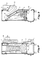
- the device shown is an oil stove 1, of which the heating body has several walls. Only one fragment of the rear wall 2 is shown.
- This rear wall 2 has a limit edge 40, 40 ′, 40 ", and, during assembly with the other walls of the body heating, it is intended to close on the rear side the heating body.
- the interior of it is, of a known manner, divided into two by means of a bottom plate 3. This supports, downwards, a pot with known liquid fuel gasification, not shown, and into which there is an air inlet oxidizer. This passes through a passage 4 provided at the bottom rear wall 2.
- the rear wall 2 is in its upper part also provided with an opening 6 whose peripheral edge 41 is located on all sides away from the edge limit 40, 40 ', 40 "from the rear wall.
- This opening has standard dimensions for all stoves alike power.
- a room tab 7 which closes it.
- the insert 7 has a passage opening 8 for the gases burned, orifice which allows communication between the inside of the heating body and the means of evacuation burnt gases.
- the insert has a shape suitable for use in a frying pan fuel oil and it supports a box 9 which includes a inlet opening 10 for flue gas, which is fitted in the passage opening 8 of the intermediate piece 7, and an outlet opening 11 to which is here connected a nozzle 12, which, in turn, can possibly be attached to a chimney flue by example. It is obvious that such a stove can also be provided without this housing 9 and, in this case, the nozzle 12 is directly connected to the passage opening 8.
- an additional opening 13 which connects the interior of the box 9 and the external environment.
- a valve possibly adjustable, can be arranged, which is not represented and which serves as a regulator of draw or cut-off and which, depending on the circumstances, lets air into the housing 9.
- the housing 9 is supported by the intermediate piece 7 of so as to leave a slight gap between these two elements.
- the external face of the intermediate piece 7 is provided with fins promoting heat exchange.
- the insert 7 supports thus a heat recovery unit where air entering 14 is evacuated in 15 after having undergone a heat exchange by convection.
- FIGS 2 to 6 show various stoves which all have an identical structure, and in particular an identical rear wall.
- this identical rear wall is provided standard opening cited above.
- the intermediate wall arranged in the standard hole in the rear wall 2 differs depending on the gas evacuation equipment burnt or heat recovery systems which must be supported on the back of the stove.
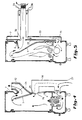
- FIG 3 In Figure 3 is shown a stove wood. On the rear wall 2 is provided the opening 6 standard according to the invention, which is closed by a insert 7 slightly inclined inwards from the stove. The insert is pierced with a passage orifice 8 for the burnt gases in which can be arranged a heat recovery unit 21. A the end thereof is provided with a nozzle 12 which communicates with a possible chimney flue.
- the insert 7 supports, on the side interior of the heater, an air duct secondary 22. This communicates an entry adjustable air outlet 23, located below the combustion chamber, and the upper part thereof.
- FIG 4 there is shown a stove liquid gasification fuel.
- the standard opening 6 according to the invention, which is closed by a piece tab 7 in which a hole is provided for passage 8 for burnt gases.
- An intermediate piece 24 guides these burnt gases to a nozzle 12.
- the stove may have a regulator draft 25, for example in the form of a valve arranged in a lower opening 26 provided in the room tab 7.
- this secondary air inlet is connected to the outside of the stove to the outside air intake 27, via a communication conduit 28.
- FIG 5 there is shown a stove suction cup gas.
- standard opening 6 according to the invention which is closed by an insert 7 in which is provided a passage orifice 8 for the burnt gases.
- a housing 29 is supported by the insert. This has an inlet opening 30 for gases burnt and an outlet opening 31 which is for example arranged outside the house in which the stove is installed.
- This box 29 supports an air box 33 comprising an air intake 34 and a preheated air outlet 35.
- This air box envelops the housing 29 and performs a heat exchange between the outgoing burnt gases and incoming air from the outlet air 34.
Landscapes
- Engineering & Computer Science (AREA)
- Chemical & Material Sciences (AREA)
- Combustion & Propulsion (AREA)
- Mechanical Engineering (AREA)
- General Engineering & Computer Science (AREA)
- Solid-Fuel Combustion (AREA)
- Yarns And Mechanical Finishing Of Yarns Or Ropes (AREA)
- Air-Conditioning For Vehicles (AREA)
- General Preparation And Processing Of Foods (AREA)
- Resistance Heating (AREA)
- Gas Burners (AREA)
Claims (22)
- Heizapparat (1), aufweisendund dadurch gekennzeichnet, daß der Heizkörper außerdem aufweisteinen Heizkörper, der aus einem Zusammenbau von mehreren Wänden gebildet ist, darunter eine durch einen Rand (40, 40', 40") begrenzte, hintere Wand (2), die den Heizkörper hinten verschließt,einen Ausgang für die verbrannten Gase,eine in der hinteren Wand vorgesehene Öffnung (6), die mit einem peripheren Rand (41) versehen ist, der in einem gewissen Abstand von dem Rand (40, 40', 40") der hinteren Wand (2) gelegen ist, wobei die Öffnung (6) vorher bestimmte Standardabmessungen für eine bestimmte Leistung des Heizapparates aufweist, aber ohne Rücksicht auf das Modell des Heizapparates oder auf den Brennstoff, der bei dem Heizapparat verwendet wird, undein Zwischenstück (7) von Standardform in Abhängigkeit von dem verwendeten Brennstoff, das in die obenerwähnte Standardöffnung (6) so eingepaßt ist, daß sie dicht verschlossen wird, und das eine Durchgangsöffnung (8) aufweist, die eine Verbindung zwischen dem Inneren des Heizkörpers und dem Ausgang für die verbrannten Gase über Mittel zur Abführung der verbrannten Gase (9, 20, 21, 24, 25 und 29) ermöglicht.
- Heizapparat gemäß Anspruch 1, dadurch gekennzeichnet, daß die Verkleidung aus emailliertem oder lackiertem Blech, mit Wänden aus Kunststoff, eventuell Verbundwänden, aus emailliertem oder lackiertem Gußeisen, oder aus Fayence ist, wobei der Apparat vom einbaubaren oder nicht einbaubaren Typ, in Säulenform, eventuell mit oberem, mittlerem oder unterem Ofen ist.
- Heizapparat gemäß Anspruch 1 oder 2, dadurch gekennzeichnet, daß der Heizköper einen Durchgang aufweist, der in der hinteren Wand (2) vorgesehen ist, und in dem ein Lufteinlaß angebracht ist.
- Heizapparat gemäß irgendeinem der vorhergehenden Ansprüche, dadurch gekennzeichnet, daß die Abführungsmittel (9, 20, 21, 24, 25, 29) für die verbrannten Gase von dem Zwischenstück getragen werden.
- Heizapparat gemäß irgendeinem der vorhergehenden Ansprüche, dadurch gekennzeichnet, daß der Ausgang für die verbrannten Gase aus einem von dem Zwischenstück (7) auf der Durchgangsöffnung (8) direkt getragenen Abführungs-Rohrstutzen (12, 31) besteht, der eventuell an einen Kaminschacht angeschlossen ist.
- Heizapparat gemäß irgendeinem der vorhergehenden Ansprüche, dadurch gekennzeichnet, daß die Abführungsmittel für die verbrannten Gase einen von dem Zwischenstück (7) getragenen Zugregler (25) aufweisen.
- Heizapparat gemäß Anspruch 6, dadurch gekennzeichnet, daß das Zwischenstück (7) eine zusätzliche Öffnung (26) umfaßt, die einen oberen Teil des Heizkörpers und einen Lufteingang (27, 28) miteinander verbindet, und in der der Zugregler (25) angebracht ist.
- Heizapparat gemäß irgendeinem der vorhergehenden Ansprüche, dadurch gekennzeichnet, daß die Abführungsmittel für die verbrannten Gase ein Gehäuse (9, 29) aufweisen, das von dem Zwischenstück (7) getragen wird, und daß dieses Gehäuse (9, 29) eine Eingangsöffnung (10, 30) für die verbrannten Gase, die in die Durchgangsöffnung (8) des Zwischenstücks (7) eingepaßt ist, und eine Ausgangsöffnung (11, 31) für die verbrannten Gase umfaßt.
- Heizapparat gemäß Anspnich 8, dadurch gekennzeichnet, daß das Gehäuse (9) eine zusätzliche Öffnung (13) umfaßt, die das Innere des Gehäuses (9) und die äußere Mitte miteinander verbindet, und in der ein Zugregler angebracht ist.
- Heizapparat gemäß Anspruch 8 oder 9, dadurch gekennzeichnet, daß das Gehäuse (9, 29) ein Wärmerekuperator ist.
- Heizapparat gemäß Anspruch 8, dadurch gekennzeichnet, daß das Gehäuse (9, 29) ein Rauchgasekasten ist.
- Heizapparat gemäß Anspruch 11, dadurch gekennzeichnet, daß das Gehäuse (29) einen Luftkasten (33) trägt, der eine Kaltluftansaugung (34) umfaßt, und einen Ausgang (35) für vorerhitzte Luft umfaßt, der in Verbindung mit einem Verbrennungslufteingang des Heizkörpers steht, wobei der Luftkasten (33) das Gehäuse (29) so umhüllt, daß ein Wärmeaustausch zwischen den in dem Gehäuse strömenden, verbrannten Gasen, und der in dem Luftkasten strömenden Luft erfolgt.
- Heizapparat gemäß irgendeinem der Ansprüche 1 bis 5, dadurch gekennzeichnet, daß der Heizkörper einen Sekundärluftschacht (22) aufweist, der von dem Zwischenstück (7) innerhalb des Heizkörpers getragen wird, und einen Lufteingang (23) und einen oberen Teil des Heizkörpers miteinander verbindet.
- Heizapparat gemäß irgendeinem der vorhergehenden Ansprüche, dadurch gekennzeichnet, daß er in der Gruppe gewählt wird, die Gasapparate, insbesondere von dem Typ mit Kamin oder von dem Typ mit Auslaßöffnung, Apparate für flüssigen Brennstoff, insbesondere mit Verdampfung unter Druck oder mit Vergasung unter Atmosphärendruck, und Apparate für Holz oder Apparate für festen Brennstoff umfaßt.
- Heizapparat gemäß irgendeinem der vorhergehenden Ansprüche, dadurch gekennzeichnet, daß das Zwischenstück (7) auf einer nach außen gerichteten Fläche Rippen aufweist, die einen Wärmeaustausch begünstigen.
- Zwischenstück (7) zum Einsetzen in eine Öffnung, die in der hinteren Wand (2) eines Heizkörpers eines Heizapparates (1) vorgesehen ist, gemäß irgendeinem der vorhergehenden Ansprüche, dadurch gekennzeichnet, daß es mindestens eine Durchgangsöffnung (8) aufweist, die eine Verbindung zwischen dem Inneren des Heizkörpers und dem Ausgang für die verbrannten Gase ermöglicht, wobei die Form des Zwischenstücks (7) ausgelegt ist, um Abführungsmittel für verbrannte Gase (9, 20, 21, 24, 25 und 29) aufzunehmen, welche die Abführung der Wäremaustauschgase und die Regelung des Zuges in Abhängigkeit von dem zu verbrennenden Brennstoff ermöglichen.
- Zwischenstück gemäß Anspruch 16, dadurch gekennzeichnet, daß die Abführungsmittel für die verbrannten Gase ein Gehäuse (9) aufweisen, das eine Eingangsöffnung (10) umfaßt, die in die Durchgangsöffnung (8) des Zwischenstücks (7) eingepaßt ist, und eine Öffnung (11) umfaßt, an die ein Rohrstutzen (12) zur Abführung der verbrannten Gase angeschlossen ist, und die eine zusätzliche Öffnung (13) umfaßt, in der eine Klappe angebracht werden kann, um den Zug zu regeln.
- Zwischenstück gemäß Anspruch 16, dadurch gekennzeichnet, daß die Abführungsmittel für die verbrannten Gase einen Reinigungskanal (20) aufweisen, um einen Kohleofen zu reinigen und die verbrannten Gase abzuführen.
- Zwischenstück gemäß Anspruch 16, dadurch gekennzeichnet, daß die Abführungsmittel für die verbrannten Gase einen Wärmerekuperator (21) für die abgeführten verbrannten Gase aufweisen.
- Zwischenstück gemäß Anspruch 16, dadurch gekennzeichnet, daß die Abführungsmittel für die verbrannten Gase ein Verbindungsstück (24) aufweisen, das die verbrannten Gase eines Ofens für flüssigen Brennstoff und Vergasung abführt, und einen Zugregler (25) in Form einer Klappe aufweisen, die in einer unteren Öffnung (26) in dem Zwischenstück (7) angeordnet ist.
- Zwischenstück gemäß Anspruch 16, dadurch gekennzeichnet, daß die Abführungsmittel für die verbrannten Gase ein Gehäuse (29) in Form eines Rauchgasekastens aufweisen, um die verbrannten Gase aus einem Gasofen von dem Typ mit Auslaßöffnung abzuführen, wobei der Rauchgasekasten eine Luftansaugung (34) und einen Ausgang (35) für die vorerhitzte Luft umfaßt.
- Verwendung eines Zwischenstücks gemäß den Ansprüchen 16 bis 21 bei einer Öffnung, die in der hinteren Wand eines Heizkörpers vorgesehen ist, bei:Heizapparaten,entweder von dem Typ mit Kamin,oder von dem Typ mit Auslaßöffnung;Heizapparaten für flüssigen Brennstoff, insbesonderemit Verdampfung unter Druck, odermit Vergasung unter Atmosphärendruck;Heizapparaten für Holz; undHeizapparaten für festen Brennstoff.
Applications Claiming Priority (3)
| Application Number | Priority Date | Filing Date | Title |
|---|---|---|---|
| BE9600172A BE1010021A3 (fr) | 1996-02-28 | 1996-02-28 | Appareil de chauffage. |
| PCT/BE1997/000018 WO1997032164A1 (fr) | 1996-02-28 | 1997-02-24 | Appareil de chauffage |
| BE9600172 | 1998-02-28 |
Publications (2)
| Publication Number | Publication Date |
|---|---|
| EP0883782A1 EP0883782A1 (de) | 1998-12-16 |
| EP0883782B1 true EP0883782B1 (de) | 2000-11-02 |
Family
ID=3889572
Family Applications (1)
| Application Number | Title | Priority Date | Filing Date |
|---|---|---|---|
| EP97903161A Expired - Lifetime EP0883782B1 (de) | 1996-02-28 | 1997-02-24 | Heizgerät |
Country Status (7)
| Country | Link |
|---|---|
| EP (1) | EP0883782B1 (de) |
| AT (1) | ATE197345T1 (de) |
| BE (1) | BE1010021A3 (de) |
| CA (1) | CA2248174C (de) |
| DE (1) | DE69703432T2 (de) |
| IL (1) | IL125870A (de) |
| WO (1) | WO1997032164A1 (de) |
Family Cites Families (5)
| Publication number | Priority date | Publication date | Assignee | Title |
|---|---|---|---|---|
| FR553427A (de) * | 1923-05-24 | |||
| FR709454A (fr) * | 1930-04-16 | 1931-08-07 | Chaboche Et Cie E | Perfectionnements aux cheminées à feu continu et autres appareils de chauffage analogues |
| FR950719A (fr) * | 1946-03-26 | 1949-10-05 | Haardenfabriek Jan Jaarsma N V | Foyer |
| GB1151741A (en) * | 1965-04-14 | 1969-05-14 | Radiation Ltd | Solid Fuel Heating Appliance |
| US4258692A (en) * | 1979-01-30 | 1981-03-31 | Washington Stove Works | Combination wood and coal stove |
-
1996
- 1996-02-28 BE BE9600172A patent/BE1010021A3/fr not_active IP Right Cessation
-
1997
- 1997-02-24 IL IL12587097A patent/IL125870A/xx not_active IP Right Cessation
- 1997-02-24 WO PCT/BE1997/000018 patent/WO1997032164A1/fr not_active Ceased
- 1997-02-24 EP EP97903161A patent/EP0883782B1/de not_active Expired - Lifetime
- 1997-02-24 AT AT97903161T patent/ATE197345T1/de not_active IP Right Cessation
- 1997-02-24 DE DE69703432T patent/DE69703432T2/de not_active Expired - Fee Related
- 1997-02-24 CA CA002248174A patent/CA2248174C/fr not_active Expired - Fee Related
Also Published As
| Publication number | Publication date |
|---|---|
| IL125870A0 (en) | 1999-04-11 |
| EP0883782A1 (de) | 1998-12-16 |
| IL125870A (en) | 2000-08-13 |
| DE69703432T2 (de) | 2001-04-19 |
| ATE197345T1 (de) | 2000-11-15 |
| CA2248174C (fr) | 2007-01-09 |
| WO1997032164A1 (fr) | 1997-09-04 |
| DE69703432D1 (de) | 2000-12-07 |
| BE1010021A3 (fr) | 1997-11-04 |
| CA2248174A1 (fr) | 1997-09-04 |
Similar Documents
| Publication | Publication Date | Title |
|---|---|---|
| CA1141607A (fr) | Chaudiere, notamment pour installation de chauffage | |
| EP1563228B1 (de) | Heizung mit hohem wirkungsgrad | |
| FR3013422B1 (fr) | Poele a granules et son procede de fonctionnement | |
| EP2923152B1 (de) | Vorrichtung zur verbesserung der verbrennung in einem kamin | |
| EP0883782B1 (de) | Heizgerät | |
| EP1640663A2 (de) | Verbesserter Gasbrenner mit nur interner Flamme | |
| BE1013297A3 (fr) | Foyer multifonctionnel. | |
| FR2473157A1 (fr) | Cheminee a foyer ouvert et foyer ferme incorpore dans le socle | |
| BE1003590A3 (fr) | Chaudiere a gaz amelioree pour montage mural du type a circulation d'air forcee et etancheite dans le local pour utilisation domestique. | |
| FR2464435A1 (fr) | Installation de chauffage | |
| FR2619893A1 (fr) | Appareil de chauffage a generation d'air chaud utilisable dans un environnement quelconque, meme combustible | |
| EP4563891A1 (de) | Ofen | |
| EP4048953B1 (de) | Kamin mit aufgehängtem herd | |
| CH652478A5 (en) | Self-contained hearth device for hot-air circulation for fireplaces | |
| FR2609157A1 (fr) | Perfectionnements a des tubes radiants a gaz | |
| FR2597197A1 (fr) | Recipient de combustion du type cheminee | |
| FR2881814A1 (fr) | Equipement pour cheminee | |
| EP1985928A1 (de) | Rundum-Heizgerät mit vorgeheizter Primärluft | |
| EP0323921A1 (de) | Gasheizkessel des gasdichten Typs mit verstellbarem Abgasventilator und damit verbundenen von einem Druckschalter Überwachten Sicherheitssystem | |
| FR2618526A1 (fr) | Coupe-tirage pour appareil de chauffage, en particulier pour cheminee equipee d'un foyer insert | |
| BE1014824A7 (fr) | Dispositf de chauffage. | |
| EP1111308A1 (de) | Heizgerät mit Luftumwälzung | |
| FR3034846A1 (fr) | Dispositif de recuperation de chaleur pour un poele et poele a bois ou charbon equipe d'un tel dispositif | |
| FR2687214A1 (fr) | Chaudiere a combustible solide, et particulierement chaudiere a bois. | |
| FR2814534A1 (fr) | Poele a bois comportant des amenagements pour la productio d'eau chaude et pour son ramonage |
Legal Events
| Date | Code | Title | Description |
|---|---|---|---|
| PUAI | Public reference made under article 153(3) epc to a published international application that has entered the european phase |
Free format text: ORIGINAL CODE: 0009012 |
|
| 17P | Request for examination filed |
Effective date: 19980813 |
|
| AK | Designated contracting states |
Kind code of ref document: A1 Designated state(s): AT BE CH DE DK ES FI FR GB GR IE IT LI LU MC NL PT SE |
|
| GRAG | Despatch of communication of intention to grant |
Free format text: ORIGINAL CODE: EPIDOS AGRA |
|
| 17Q | First examination report despatched |
Effective date: 19990913 |
|
| GRAG | Despatch of communication of intention to grant |
Free format text: ORIGINAL CODE: EPIDOS AGRA |
|
| GRAG | Despatch of communication of intention to grant |
Free format text: ORIGINAL CODE: EPIDOS AGRA |
|
| GRAH | Despatch of communication of intention to grant a patent |
Free format text: ORIGINAL CODE: EPIDOS IGRA |
|
| GRAH | Despatch of communication of intention to grant a patent |
Free format text: ORIGINAL CODE: EPIDOS IGRA |
|
| GRAA | (expected) grant |
Free format text: ORIGINAL CODE: 0009210 |
|
| AK | Designated contracting states |
Kind code of ref document: B1 Designated state(s): AT BE CH DE DK ES FI FR GB GR IE IT LI LU MC NL PT SE |
|
| PG25 | Lapsed in a contracting state [announced via postgrant information from national office to epo] |
Ref country code: FR Free format text: LAPSE BECAUSE OF FAILURE TO SUBMIT A TRANSLATION OF THE DESCRIPTION OR TO PAY THE FEE WITHIN THE PRESCRIBED TIME-LIMIT Effective date: 20001102 Ref country code: FI Free format text: LAPSE BECAUSE OF FAILURE TO SUBMIT A TRANSLATION OF THE DESCRIPTION OR TO PAY THE FEE WITHIN THE PRESCRIBED TIME-LIMIT Effective date: 20001102 Ref country code: ES Free format text: THE PATENT HAS BEEN ANNULLED BY A DECISION OF A NATIONAL AUTHORITY Effective date: 20001102 Ref country code: AT Free format text: LAPSE BECAUSE OF FAILURE TO SUBMIT A TRANSLATION OF THE DESCRIPTION OR TO PAY THE FEE WITHIN THE PRESCRIBED TIME-LIMIT Effective date: 20001102 |
|
| REF | Corresponds to: |
Ref document number: 197345 Country of ref document: AT Date of ref document: 20001115 Kind code of ref document: T |
|
| REG | Reference to a national code |
Ref country code: CH Ref legal event code: EP |
|
| REG | Reference to a national code |
Ref country code: CH Ref legal event code: NV Representative=s name: CABINET ROLAND NITHARDT CONSEILS EN PROPRIETE INDU |
|
| REF | Corresponds to: |
Ref document number: 69703432 Country of ref document: DE Date of ref document: 20001207 |
|
| GBT | Gb: translation of ep patent filed (gb section 77(6)(a)/1977) |
Effective date: 20001116 |
|
| REG | Reference to a national code |
Ref country code: IE Ref legal event code: FG4D Free format text: FRENCH |
|
| ITF | It: translation for a ep patent filed | ||
| PG25 | Lapsed in a contracting state [announced via postgrant information from national office to epo] |
Ref country code: SE Free format text: LAPSE BECAUSE OF FAILURE TO SUBMIT A TRANSLATION OF THE DESCRIPTION OR TO PAY THE FEE WITHIN THE PRESCRIBED TIME-LIMIT Effective date: 20010202 Ref country code: PT Free format text: LAPSE BECAUSE OF FAILURE TO SUBMIT A TRANSLATION OF THE DESCRIPTION OR TO PAY THE FEE WITHIN THE PRESCRIBED TIME-LIMIT Effective date: 20010202 Ref country code: DK Free format text: LAPSE BECAUSE OF FAILURE TO SUBMIT A TRANSLATION OF THE DESCRIPTION OR TO PAY THE FEE WITHIN THE PRESCRIBED TIME-LIMIT Effective date: 20010202 |
|
| PG25 | Lapsed in a contracting state [announced via postgrant information from national office to epo] |
Ref country code: GR Free format text: LAPSE BECAUSE OF FAILURE TO SUBMIT A TRANSLATION OF THE DESCRIPTION OR TO PAY THE FEE WITHIN THE PRESCRIBED TIME-LIMIT Effective date: 20010203 |
|
| PG25 | Lapsed in a contracting state [announced via postgrant information from national office to epo] |
Ref country code: LU Free format text: LAPSE BECAUSE OF NON-PAYMENT OF DUE FEES Effective date: 20010224 |
|
| PG25 | Lapsed in a contracting state [announced via postgrant information from national office to epo] |
Ref country code: MC Free format text: LAPSE BECAUSE OF NON-PAYMENT OF DUE FEES Effective date: 20010228 Ref country code: LI Free format text: LAPSE BECAUSE OF NON-PAYMENT OF DUE FEES Effective date: 20010228 Ref country code: CH Free format text: LAPSE BECAUSE OF NON-PAYMENT OF DUE FEES Effective date: 20010228 |
|
| PLBE | No opposition filed within time limit |
Free format text: ORIGINAL CODE: 0009261 |
|
| STAA | Information on the status of an ep patent application or granted ep patent |
Free format text: STATUS: NO OPPOSITION FILED WITHIN TIME LIMIT |
|
| REG | Reference to a national code |
Ref country code: CH Ref legal event code: PL |
|
| 26N | No opposition filed | ||
| REG | Reference to a national code |
Ref country code: GB Ref legal event code: IF02 |
|
| PGFP | Annual fee paid to national office [announced via postgrant information from national office to epo] |
Ref country code: IE Payment date: 20030212 Year of fee payment: 7 |
|
| PGFP | Annual fee paid to national office [announced via postgrant information from national office to epo] |
Ref country code: GB Payment date: 20030213 Year of fee payment: 7 |
|
| PGFP | Annual fee paid to national office [announced via postgrant information from national office to epo] |
Ref country code: NL Payment date: 20030217 Year of fee payment: 7 |
|
| PGFP | Annual fee paid to national office [announced via postgrant information from national office to epo] |
Ref country code: DE Payment date: 20030821 Year of fee payment: 7 |
|
| PG25 | Lapsed in a contracting state [announced via postgrant information from national office to epo] |
Ref country code: IE Free format text: LAPSE BECAUSE OF NON-PAYMENT OF DUE FEES Effective date: 20040224 Ref country code: GB Free format text: LAPSE BECAUSE OF NON-PAYMENT OF DUE FEES Effective date: 20040224 |
|
| PG25 | Lapsed in a contracting state [announced via postgrant information from national office to epo] |
Ref country code: NL Free format text: LAPSE BECAUSE OF NON-PAYMENT OF DUE FEES Effective date: 20040901 Ref country code: DE Free format text: LAPSE BECAUSE OF NON-PAYMENT OF DUE FEES Effective date: 20040901 |
|
| GBPC | Gb: european patent ceased through non-payment of renewal fee |
Effective date: 20040224 |
|
| NLV4 | Nl: lapsed or anulled due to non-payment of the annual fee |
Effective date: 20040901 |
|
| REG | Reference to a national code |
Ref country code: IE Ref legal event code: MM4A |
|
| PG25 | Lapsed in a contracting state [announced via postgrant information from national office to epo] |
Ref country code: IT Free format text: LAPSE BECAUSE OF NON-PAYMENT OF DUE FEES;WARNING: LAPSES OF ITALIAN PATENTS WITH EFFECTIVE DATE BEFORE 2007 MAY HAVE OCCURRED AT ANY TIME BEFORE 2007. THE CORRECT EFFECTIVE DATE MAY BE DIFFERENT FROM THE ONE RECORDED. Effective date: 20050224 |
|
| PGFP | Annual fee paid to national office [announced via postgrant information from national office to epo] |
Ref country code: BE Payment date: 20080125 Year of fee payment: 12 |
|
| BERE | Be: lapsed |
Owner name: *THERMIC INVESTMENTS Effective date: 20090228 |
|
| PG25 | Lapsed in a contracting state [announced via postgrant information from national office to epo] |
Ref country code: BE Free format text: LAPSE BECAUSE OF NON-PAYMENT OF DUE FEES Effective date: 20090228 |