EP0860828A2 - Enregistrement et reproduction d'information - Google Patents
Enregistrement et reproduction d'information Download PDFInfo
- Publication number
- EP0860828A2 EP0860828A2 EP98301318A EP98301318A EP0860828A2 EP 0860828 A2 EP0860828 A2 EP 0860828A2 EP 98301318 A EP98301318 A EP 98301318A EP 98301318 A EP98301318 A EP 98301318A EP 0860828 A2 EP0860828 A2 EP 0860828A2
- Authority
- EP
- European Patent Office
- Prior art keywords
- recording medium
- file
- information
- recording
- block
- Prior art date
- Legal status (The legal status is an assumption and is not a legal conclusion. Google has not performed a legal analysis and makes no representation as to the accuracy of the status listed.)
- Withdrawn
Links
Images








Classifications
-
- G—PHYSICS
- G06—COMPUTING OR CALCULATING; COUNTING
- G06F—ELECTRIC DIGITAL DATA PROCESSING
- G06F12/00—Accessing, addressing or allocating within memory systems or architectures
-
- G—PHYSICS
- G11—INFORMATION STORAGE
- G11B—INFORMATION STORAGE BASED ON RELATIVE MOVEMENT BETWEEN RECORD CARRIER AND TRANSDUCER
- G11B27/00—Editing; Indexing; Addressing; Timing or synchronising; Monitoring; Measuring tape travel
- G11B27/10—Indexing; Addressing; Timing or synchronising; Measuring tape travel
- G11B27/19—Indexing; Addressing; Timing or synchronising; Measuring tape travel by using information detectable on the record carrier
- G11B27/28—Indexing; Addressing; Timing or synchronising; Measuring tape travel by using information detectable on the record carrier by using information signals recorded by the same method as the main recording
- G11B27/32—Indexing; Addressing; Timing or synchronising; Measuring tape travel by using information detectable on the record carrier by using information signals recorded by the same method as the main recording on separate auxiliary tracks of the same or an auxiliary record carrier
- G11B27/327—Table of contents
- G11B27/329—Table of contents on a disc [VTOC]
-
- G—PHYSICS
- G11—INFORMATION STORAGE
- G11B—INFORMATION STORAGE BASED ON RELATIVE MOVEMENT BETWEEN RECORD CARRIER AND TRANSDUCER
- G11B27/00—Editing; Indexing; Addressing; Timing or synchronising; Monitoring; Measuring tape travel
- G11B27/02—Editing, e.g. varying the order of information signals recorded on, or reproduced from, record carriers
- G11B27/031—Electronic editing of digitised analogue information signals, e.g. audio or video signals
-
- G—PHYSICS
- G11—INFORMATION STORAGE
- G11B—INFORMATION STORAGE BASED ON RELATIVE MOVEMENT BETWEEN RECORD CARRIER AND TRANSDUCER
- G11B27/00—Editing; Indexing; Addressing; Timing or synchronising; Monitoring; Measuring tape travel
- G11B27/10—Indexing; Addressing; Timing or synchronising; Measuring tape travel
- G11B27/102—Programmed access in sequence to addressed parts of tracks of operating record carriers
- G11B27/105—Programmed access in sequence to addressed parts of tracks of operating record carriers of operating discs
-
- G—PHYSICS
- G11—INFORMATION STORAGE
- G11B—INFORMATION STORAGE BASED ON RELATIVE MOVEMENT BETWEEN RECORD CARRIER AND TRANSDUCER
- G11B2220/00—Record carriers by type
- G11B2220/20—Disc-shaped record carriers
- G11B2220/25—Disc-shaped record carriers characterised in that the disc is based on a specific recording technology
- G11B2220/2525—Magneto-optical [MO] discs
-
- G—PHYSICS
- G11—INFORMATION STORAGE
- G11B—INFORMATION STORAGE BASED ON RELATIVE MOVEMENT BETWEEN RECORD CARRIER AND TRANSDUCER
- G11B2220/00—Record carriers by type
- G11B2220/60—Solid state media
- G11B2220/61—Solid state media wherein solid state memory is used for storing A/V content
Definitions
- the present invention relates to recording and reproducing information.
- Fig. 1 of the accompanying drawings illustrates an outer appearance of apparatus for recording and reproducing information as proposed in the foregoing publications.
- the information recording and reproducing apparatus 200A provides a coupling terminal 201 to be coupled with an information feeding apparatus (not shown), through which information is allowed to be copied from the information feeding apparatus to a recording medium (not shown) provided inside of the information recording and reproducing apparatus 200A.
- This apparatus does not specify a type of the recording medium.
- This information recording and reproducing apparatus 200A includes a display panel 202 for displaying text and pictures and a function selector 203 composed of push buttons. This information recording and reproducing apparatus 200A is arranged so that the information recorded in the recording medium may be displayed on the display panel 202. Hence, the user can select any desired information with the function selector 203 and reproduce the selected information.
- the content of the information fed by the information feeding apparatus contains text information, speech information, picture information, and computer programs but is not specifically limited.
- the reproduction of the program indicates execution of the program. In this case, during the execution, the user may enter information as required. If the reproduction signal is text information or a video signal, it may be displayed on the display panel 202 composed of a liquid crystal display panel. Further, if it is speech information, it may be outputted to an earphone 204. Though not shown, in place of the earphone 204, a speaker may be equipped therewith. In addition, an output terminal for the reproduction signal maybe provided so that the apparatus may be connected to an external display or a speaker therethrough.
- Fig.2 illustrates an outer appearance of another apparatus for recording and reproducing information proposed in the foregoing publications.
- the information recording and reproducing apparatus 200B shown in Fig.2 is arranged by separating the information recording and reproducing apparatus 200A shown in Fig.1 into the information recording apparatus 210 and the information reproducing information 220.
- This information recording and reproducing apparatus 200B is arranged so that an information recording apparatus 210 is inserted into an insertion port 221 of an information reproducing apparatus 220.
- the information may be transmitted from the information recording apparatus 210 to the information reproducing apparatus 220 so that the information may be reproduced therein.
- the information recording apparatus 210 provides a coupling terminal 212 to be coupled with the information reproducing apparatus 220. Further, the information reproducing apparatus provides the corresponding coupling terminal (not shown) to the terminal 212. When the information recording apparatus 210 is mounted with the information reproducing apparatus 220, both of the coupling terminals are coupled with each other.
- the information recording apparatus 210 provides two coupling terminals, the coupling terminal 211 to be coupled with the information feeding apparatus and the coupling terminal 212 to be coupled with the information reproducing apparatus. In place, the apparatus 210 may provide a single coupling terminal to be switched for each purpose.
- the information recording apparatus 210 may be composed of only the recording medium. If it is composed of only the recording medium, the resulting information recording apparatus 210 is small and lightweight. In this case, the control of reading or writing the information from or to the recording medium is executed on the information reproducing apparatus 220 or the information feeding apparatus side.
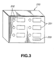
- Fig.3 illustrates an outer appearance of the information feeding apparatus proposed in the foregoingpublication.
- This information feeding apparatus 230 provides display units 231 for indicating the content and the price ofinformation to be fed, for example, and output selectors 232 for selecting information desired by the user.
- the user connects the information recording apparatus 210 shown in Fig.2 into an insertion port 233 of the information feeding apparatus 230.
- the coupling terminal (not shown) provided in the information feeding apparatus 230 may be connected to the coupling terminal 201 of the information recording and reproducing apparatus 200A shown in Fig.1.
- the information feeding apparatus 230 provides a recording medium for saving information to be fed and an information copy control unit (not shown) for reading information desired by the user from the recording medium and writing the read information into the information recording apparatus 210 and the information recording and reproducing apparatus 200A.
- the information feeding apparatus 230 is connected to an information feeding center (not shown) by wired or wireless communicating means. The user may request his or her desired information through the communicating means.
- the recording medium is not required to provide in the information feeding apparatus 230. If the recording medium is provided inside of the information feeding apparatus 230, by updating the information saved in the recording medium, the information feeding apparatus 230 may feed the latest information though it can suppress the communication cost.
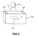
- Fig.4 illustrates an outer appearance of another information feeding apparatus 240 proposed in the foregoing publication.
- This information feeding apparatus 240 provides an insertion port 241 and an ejection port 242 used for the information recording apparatus 210, both of which ports and outlet are separated by a certain distance.
- This information feeding apparatus 240 provides moving means (not shown) for conveying the information recording apparatus 210 inserted from the insertion port 241. The information to be fed is copied in the inserted information recording apparatus 210. Then, the information recording apparatus 210 is ejected from the ejection port 242.
- a person H who wants to obtain information can obtain a copy of information as he or she is walking in the direction of an arrow A in Fig.4.
- This information feeding apparatus 240 thus provides a capability of swiftly feeding information to many persons.
- Japanese Patent Application No. Hei 8-228966 means for managing a file in the case of using a recording medium whose erasing unit (referred to as a block) is larger than a writing unit (referred to as a page).
- This file managing means is a system of recording all files containing divided files from a head address of a block or if a recording medium is composed of plural recording medium pieces, regularly and vertically recording all files from the logically head medium piece.
- Fig.5 illustrates the state of recording files if the recording medium is composed of plural recording medium pieces and the file managing means 300.
- the description will be expanded with an example of the recording medium 303 composed of four recording medium pieces 303a, 303b, 303c and 303d in which one block is composed of four pages.
- the block denotes an erasing unit of data.
- the page denotes a writing unit of data.
- C denotes a number c of a memory chip
- B denotes a number b of a block, that is, a minimum erasing unit
- P denotes a number p of a page, that is, a minimum writing unit.
- the physical address is represented as CBP[c:b:p].
- one page has the same capacitance as one sector, that is, 512 bytes, for the purpose of facilitating the correspondence with the so-called FAT (File Allocation Table) file system or the like.
- F denotes a number f of files
- S denotes a number s of sectors composing one file.
- the data is represented as FS [f:s].
- each of the recording medium pieces C[0], C[1], C[2] and C[3] is composed of four blocks from B[0] to B[3], each of which is composed of four pages from P[0] to P[3].
- the file managing means 300 is arranged to record and manage a name (File), a number, a size, a head address (Loc) or the like of each file recorded on the recording medium 303 from the recording medium M[0] to M[m-1] as well as manage a logical sequence of each file.
- m denotes a number of maximum files to be managed by the file managing means 300.
- a value described in the file managing means 300 in Fig.5 minus 1 indicates invalid file management data.
- the sector data of each file is recorded regularly over four recording medium pieces in the sequence of 303b, 303c, and 303d from the recording medium piece 303a as a head.
- the file managing means 300 indicates the following information. Three files are recorded inside of the recording medium 303, in which the logical sequence of these files are F[1], F[2] and F[0].
- the file F[1] is recorded on the capacitance of 23 sectors started from the head address CBP[0:1:0] of the block B[1].
- the file F[2] is recorded on the capacitance of 13 sectors started from the head address CBP[0:3:0] of the block B[3].
- the file F[0] is recorded on the capacitance of 12 sectors started from the head address CBP[0:0:0] of the block B[0].
- the description will be oriented to the rewrite of the file F[1] in Fig.5.
- the recording medium 303 is composed of four recording medium pieces and each recording medium piece is composed of four blocks each of which is composed of four pages.
- the file managing means 300 that the file F[1] contains a capacitance of 23 sectors started from the head address CBP[0:1:0] of the block B[1]. That is, the file F[1] is made up of eight blocks over four recording medium pieces.
- the block erasing operation is executed for the blocks CB[0:1], CB[1:1], CB[2:1], CB[3:1], C3[0:2], CB[1:2], CB[2:2] and CB[3:2].
- the write of a new file is started.
- the sector data from FS[1:0] to FS[1:22] in the sequence of FS[1:0], FS[1:1], FS[1:2], FS[1:3], FS[1:4],... illustrated in Fig.5 are recorded over the recording medium pieces 303a, 303b, 303c and 303d.
- the reading sequence of the sector data for the reading operation is executed in the same manner as that for the foregoing writing operation.
- the file F[1] includes a capacitance of 23 sectors started from the head address CBP [0:1:0] of the block B[1].
- the sector data from FS[1:0] to FS[1:22] in the sequence of FS[1:0], FS[1:1], FS[1:2], FS[1:3], FS[1:4]... illustrated in Fig.5 are vertically read out of four recording medium pieces.
- Nonvolatile memory As a recording medium used in the case of requesting the information recording and reproducing apparatus to be portable, by using a nonvolatile memory that does not need to back up the information with a cell, no recorded information is lost. This is favorable.
- This kind of nonvolatile memory may be the so-called EEPROM (Electrically Erasable and Programmable ROM) described in Iwata, et.al., "32-Mbits NAND flash memory” (Electronic Material Magazine, June, 1995, pp.32 to 37).
- the means 300 for managing file recording states and files is executed to realize parallel control of the recording medium pieces and easy file management by following the condition that only one kind of file is recorded in one block and the condition that the regular control sequence is executed for plural recording medium pieces.
- the file F[1] of Fig.5 is recorded on eight blocks, it may be stored in the capacitance of 23 sectors, that is, six blocks. Likewise, the file F[0] is recorded over four blocks though it just needs the capacitance of 12 sectors stored in three blocks.
- This recording system has tendency to having empty blocks reduced though empty pages are left in the recording medium 303. Hence, it may be in some cases difficult to secure an empty area (empty block) for recording a new file.
- the blocks to be erased is made numerous when rewriting the file. Hence, it needs a longer erasing operation than the system in which the data is packed inside of the block. This is unfavorable for the system that is essential to fast rewriting operation.
- the recording system arranged to sequentially pack the sector data pieces of one file inside of a block has difficulty in parallel control of the recording medium pieces and speeding up the rewrite of the data.
- Embodiments of the present invention can provide an information recording and reproducing apparatus provided with a recording medium composed of plural recording medium pieces which provides a capability of more efficiently and flexibly managing a memory without lowering a reading speed and a writing one.
- the information recording and reproducing apparatus is arranged to manage the recording area of the recording medium composed of plural information-rewritable recording medium pieces as a one-dimensional sequence (block sequence) of blocks located regularly and circularly in the vertical direction and control the recording medium based on the file management information.
- the file is composed of a block sequence (file block sequence) of any length and is written in the recording medium from any head address together with the file management information stored therein.
- the information recording and reproducing apparatus makes it possible to read from the recording medium a file composed of a block sequence of any length (file block sequence) recorded from any head address.
- the method and the apparatus for recording and reproducing information which are composed of plural recording medium pieces such as a flash memory, are arranged to consider the memory area as a one-dimensional block sequence regularly and vertically located over plural recording medium pieces and compose the file of a file block sequence of a block sequence of any length. Further, by enabling the write at any head address, the method and apparatus provide a capability of doing fast parallel control and efficiently using a memory through the use of simple file managing means.
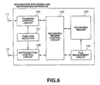
- Fig.6 is a block diagram showing an overall arrangement of an apparatus for recording and reproducing information according to an embodiment of the invention.
- a numeral 1 denotes an information recording and reproducing apparatus.
- This apparatus 1 includes a function selector 101, a recording medium 103, a file management circuit 104, a recording medium control circuit 102, a transfer control circuit 105, and a reproduction control circuit 106.
- the function selector 101 is inputted with a function desired and selected by a user, such as a recording or a reproduction.
- the recording medium 103 is composed of plural recording medium pieces.
- the file management circuit 104 operates to manage files recorded on the recording medium 103.
- the recording medium control circuit 102 operates to control operations of reading, writing and erasing a file relative to the recording medium 103 in concert with the file management circuit 104.
- the transfer control circuit 105 operates to control the input of data to the apparatus 1 or the output of data from the apparatus 1 through a terminal 11.
- the reproduction control circuit 106 operates to reproduce the file recorded on the recording medium and output it to the terminal 12.
- the function selector 101 is set to write the file inputted and transferred from the terminal 11 onto the recording medium 103.
- the recording medium control circuit 102 operates to exert the file management circuit 104 to retrieve an empty area inside of the recording medium 103.
- the transfer control circuit 105 operates to execute a low-order transfer protocol (to be discussed below) so that it may read the input data.
- the recording medium control circuit 102 operates to execute a high-order transfer protocol (to be discussed below) so that it may enter the input data on the recording medium 103 as a file.
- the recording medium control circuit 102 operates to record file management information corresponding to the written file onto the file management circuit 104.
- the low-order transfer protocol may be the ANSI X3.131-1986 standards called SCSI (Small Computer System Interface), the so-called IEEE 1394 standards, or the standards containing a physical layer such as PC card standards of PCMCIA (Personal Computer Memory Card International Association).
- SCSI Serial Computer System Interface
- IEEE 1394 the standards containing a physical layer
- PC card standards of PCMCIA Personal Computer Memory Card International Association
- the recording medium control circuit 102 preferably provides a capability of controlling the recording medium 103 without impairing a data transfer performance held by the transfer control circuit 105. That is, the whole data transfer performance of the information recording and reproducing apparatus 1 depends on the lower one of the transfer control capability of the transfer control circuit 105 and the recording medium control capability of the recording medium control circuit 102. Hence, the information recording and reproducing apparatus 1 is inevitably required to have highly efficient transfer control circuit and recording medium control circuit.
- the present applicant has disclosed the technique of "Means for Transferring Information and Means for Recording Information" in the Japanese Laid-open No. Hei 7-200181 as this kind of system of writing a file in the high-order transfer protocol, employed in the recording medium control circuit 102. This technique makes it possible to write a file on the recording medium 103 at fast speed. That is, the recording medium control circuit 102 operates to write the data on plural recording medium pieces composing the recording medium 103 in parallel as will be discussed below.
- the recording medium 103 composed of plural recording medium pieces is composed of a semiconductor memory such as the foregoing NAND type flash memory
- a chip select signal is given to a memory chip where data is to be written.
- a command is given to the recording medium 103 for indicating an input operation of serial data.
- the operation is executed to enter an address where data is to be written and transfer and input the data of one page, that is, 512 bytes from the transfer control circuit 105 to an internal register of the memory chip.
- the operation is executed to enter a command for doing a writing operation. As a result of those operations, a specific time later, the data of 512 bytes is written from the internal register to the memory cell, where the writing operation of one page is completed.
- the recording medium control circuit 102 operates to sequentially enter the similar command address and data onto another recording medium piece before the specific time.
- the file management circuit 104 operates to update the file management information.
- the function selector 101 is set to read the file recorded on the recording medium 103 and transfer and output it onto the terminal 11.
- a user of the apparatus 1 specifies a file to be transferred and outputted to the terminal 11 by referring to the file management circuit 104.
- the recording medium control circuit 102 exerts the file management circuit 104 to retrieve the management information about the file for recognizing a recording address and a capacitance.
- the recording medium control circuit 102 operates to execute a high-order transfer protocol for reading out a file specified, and the transfer control circuit 105 executes a low-order transfer protocol for outputting the file through the terminal 11.
- the recording medium control circuit 102 preferably provides a capability of controlling the recording medium 103 without impairing a data transfer performance held by the transfer control circuit 105.
- the high-order transfer protocol is executed to read data in parallel.
- a chip select signal is given to a memory chip from which data is read. Then, a command for a reading operation is given to the memory chip. Next, by entering an address from which data is to be read, the operation is executed to read the data of one page, that is, 512 bytes from the address of the memory cell specified after a specific time to the internal register of the memory chip. Lastly, by transferring the data to the transfer control circuit 105, the operation of reading the data of one page is completed.
- the recording medium control circuit 102 operates to execute the parallel input of the similar command and address to another recording medium piece before the specific time, for the purpose of enhancing a data reading speed.
- the function selector 101 is set to read the data recorded on the recording medium 103 and reproduce and output it to the terminal 12.
- the user of this apparatus 1 refers to the file management circuit 104 for specifying a file to be reproduced and outputted.
- the recording medium control circuit 102 exerts the file management circuit 104 to retrieve the management information about the file and recognize the recording address and the capacitance of the file.
- the recording medium control circuit 102 operates to execute the high-order transfer protocol and read the data composing the specified file.
- the reproduction control circuit 106 executes the reproducing process about the data read by the recording medium control circuit 102 and then outputs the reproduced data from the terminal 12.
- the reproducing process depends on the type of information recorded on the recording medium. If the file is coded, the corresponding decoding process is executed with respect to the data. For example, if the file of the recording medium 103 is encoded by the so-called MPEG algorithm, the reproduction control circuit 106 operates to decode the file according to the MPEG algorithm.
- the recording medium 103 of the information recording and reproducing apparatus 1 a disk medium such as a semiconductor memory medium, a magneto-optical disk, or a magnetic disk to be accessed at random.
- a nonvolatile memory results in eliminating the necessity of providing a power supply for holding information, thereby reducing the apparatus in size.
- the memory may be a rewritable nonvolatile memory such as a flash memory.
- Fig.7 shows the file recording state and the file management circuit 104 according to the embodiment of the invention, for the purpose of solving the problems of the prior art shown in Fig.5.
- each file is recorded regularly and vertically on plural recording medium pieces, while unlike the prior art of Fig.5, each file is not necessarily required to be vertically recorded on the sequential recording medium pieces.
- the file recorded on the four recording medium pieces 103a, 103b, 103c and 103d has the same recording content (sector data) as the file recorded as shown in Fig.5 though the recording locations of the file shown in Fig.7 are different from those of the file shown in Fig.5.
- the oblique portions of the recording medium pieces 103a and 103b indicate a block (invalid block) caused in manufacturing the recording medium piece or excessive rewriting or a block whose file is inhibited to be rewritten (system block) for the purpose of securing a system area or a spare area.
- the recording medium 103 of this embodiment is composed of four recording medium pieces 103a, 103b, 103c and 103d.
- one block is composed of four pages.
- the block refers to a data erasing unit and the page refers to a data writing unit as described above.
- C denotes a number c of a memory chip
- B denotes a number b of the block, that is, a minimum erasing unit
- P denotes a number p of the page, that is, a minimum writing unit.
- the physical address is represented as CBP[c:b:p].
- the description will be expanded on that the capacitance for one page is 512 bytes that is the same as the capacitance of one sector, for the purpose of facilitating the correspondence with the so-called FAT (File Allocation Table) file system.
- F F denotes a number f of the file
- S denotes a number s of the sectors composing the file.
- the recorded data is represented as FS[f:s].
- each of the recording medium pieces C[0], C[1], C[2] and C[3] (that is, 103a, 103b, 103c, 103d) is composed of four blocks from B[0] to B[3]. Each block is composed of four pages from P[0] to P[3].
- the file management circuit 104 operates to record the information of each file recorded on the recording medium 103 such as a name (File), a number, a size, and a location on M[0] to m[m-1] and manage the information as well as manage the logical sequence of each file, in which m denotes a maximum number of files to be managed by the file management circuit 104.
- the value described in the file management circuit 104 minus 1 indicates invalid file management data.
- the file management information contained in this file management circuit 104 indicates the following. Three files are recorded on the recording medium 103. The logical sequence of these files are F[1], F[2], and F[0].
- the file F[1] has a capacitance of 23 sectors.
- the file F[2] has a capacitance of 13 sectors.
- the file F[0] has a capacitance of 12 sectors.
- the file F[1] is recorded on the capacitance of 23 sectors started from the block CB[2:1] of the recording medium piece C[2] (103c) as the head address CBP[2:1:0].
- the file F[2] is recorded on the capacitance of 13 sectors started from the b1ock ⁇ CB[0:3] of the recording medium piece C[0] (103a) as the head address address CBP[0:3:0].
- the file F[0] is recorded on the capacitance of 12 sectors started from the block [1:0] of the recording medium piece C[1] (103b) as the head address CBP[1:0:0].
- the number of blocks composing each file can be easily grasped from the fact that one block is composed of four pages and a capacitance value (page number) described in the file management circuit 104.
- page number page number
- the file management circuit 104 records the capacitance of the file F[0] as 12 pages, it is easily grasped that the file F[0] is composed of three blocks. Hence, it is grasped that the file F[0] is composed of a block sequence of CB[1:0], CB[2:0] and CB[3:0].
- Fig.5 which illustrates the foregoing prior art
- the file F[0] is recorded vertically on four blocks
- Fig.7 the file F[0] is recorded vertically on three blocks.
- the block CB[0:0] is used as a system block
- the blocks CB[1:0], CB[2:0], and CB[3:0] are unable to record and manage the file.
- the use of the file management circuit 104 makes it possible to identify only the block CB[0:0] as the system block. Further, the circuit 104 operates to individually manage the file F[0] composed of the adjacent three blocks.
- the file F[1] is recorded vertically on eight blocks, while it is recorded on six blocks. Further, in Fig.5, if the block CB[1:1] is an invalid block, the files recorded on the blocks CB[0:1], CB[2:1] and CB[3:1] are not allowed to be managed. However, by introducing the block management circuit 104 shown in Fig.7, it is possible to record and manage the files recorded on these blocks.
- the recording medium is composed of plural recording medium pieces
- the recording area is regarded as a one-dimensional block sequence vertically and regularly located on the recording medium pieces and the file is composed of a file block sequence of any length. Further, by enabling the write at any head address, it is possible to efficiently implement the parallel control of writing and the retrieval of an empty area as well as to use the recording area through the effect of a simple file management circuit.
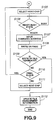
- Figs.8 and 9 are flowcharts for illustrating the operation of the recording medium control circuit 102 if a transfer input operation for a file is specified by the function selector 101.
- the block sequence composing a file to be controlled is called as follows.
- the block being controlled is referred to as a current block.
- the block adjacent to the current block and to be controlled next is referred to as a next block.
- the recording medium piece containing the current block is referred to as a current chip.
- the recording medium piece containing the next block is referred to as a next chip.
- the head block of the block sequence is referred to as a head block.
- the recording medium piece containing the head block is referred to as a head chip.
- the tail block of the block sequence is referred to as a last black.
- the recording medium piece containing the current block if the next block is contained in the head chip is referred to as a last chip.
- the recording medium control circuit 102 recognizes the operation of writing the data transmitted from the transfer control circuit 105 to the recording medium 103.
- the user specifies the information about a file to be written, such as a file name and a capacitance through the information recording and reproducing apparatus 1.
- the file management circuit 104 is executed to retrieve an empty area of the recording medium 103. Then, at the next step S104, If it is determined that there exists an empty area (Yes), the process of writing a file on the recording medium 103 is started from the next step. On the other hand, at the step S104, if it is determined that there exists no empty area (No), an operation of erasing a block (to be discussed below) is executed for securing an empty area.
- the file management circuit 104 it is possible to calculate out a total capacitance of the files recorded on the recording medium 103. Hence, it is possible to easily determine if there exists an empty area.
- the file to be erased for securing an empty area is made to be the logically oldest file. In place, the user of the apparatus 1 may select the file to be erased through the function selector 101.
- a chip select signal is inputted to the head chip for controlling the write.
- a ready/busy state is checked as the status information of the current chip. Until the current chip reaches the ready state, the operation is waiting at this step.
- the recording medium piece selected for the first time since the operation of writing the file is started normally keeps the ready state.
- the step S104 if the operation is branched into an erasing operation (No), it may not keep the ready state (Busy) because the medium piece is being erased.
- the write of the sector data is executed along the foregoing writing procedure.
- the sector data written at the step S108 is written sequentially from the head address of the current block.
- step S109 it is determined if the write for all the blocks composing a file is terminated. If it is terminated (Yes), at a step S112, the management information of the written file is updated and newly recorded in the file management circuit 104, and then the operation of inputting and transferring the file is terminated.
- next step S110 it is determined if the current block is the last block. If at the step S110 it is determined that the current block is the last block (Yes), the operation returns to the step S105 at which the head chip is selected. Then, the foregoing process is repeated from the next page at the head block. On the other hand, if it is determined that it is not the last block (NO), at the next step S111, the next chip is selected. Then, from the step S106, the foregoing process is repeated.
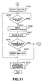
- Figs.10 and 11 are flowcharts for illustrating the operation of the information recording and reproducing apparatus 1 if the operation of erasing the file is specified by the function selector 101.
- the recording medium control circuit 102 operates to recognize execution.of an erasing operation for a file specified at the next step S202.
- the user of the information recording reproducing apparatus 1 specifies information about a file to be erased, such as a file name.
- the file management circuit 104 is executed to retrieve the specified file.
- a chip select signal is inputted to the head chip for erasing control.
- the step S104 of the writing operation shown in Fig.8 if it is determined that no empty area is left (No), the operation is branched into the step S204.
- the next step S205 it is checked if the current chip is a ready or a busy state. The operation is waiting until the current chip reaches the ready state.
- the recording medium Piece to be selected for the first time since the operation of erasing the file is started is normally kept ready.
- the erasion of the block is executed. During this execution, the operation may go to the next step without having to wait for the termination of the erasion.
- next step S208 it is determined if the erasion for all blocks composing the file is completed. If completed (Yes), at a step S210, the file management circuit 104 is executed to delete the management information about the erased file, and then the operation of erasing the file is terminated. During the writing operation described in Figs.8 and 9, if the operation is branched into the step S204, without doing the process at the step S210, the operation goes back to the step S105 contained in the writing operation shown in Fig.9. On the other hand, if it is determined that the write of the file is not terminated (No), at the next step S209, the next chip is selected, and the foregoing process is repeated from the step S205.
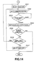
- Figs.12 to 14 are flowcharts for illustrating the operation of the information recording and reproducing apparatus 1 if the function selector 101 is executed to specify the operation of reading the file.
- the operation of reading the file in the case of transferring it is different from that in the case of reproducing it.
- the recording medium control circuit 102 operates to recognize execution of the operation of reading a file specified at the next step S302.
- the user of the apparatus 1 specifies information about the file to be read for transferred output or reproduced output, such as a file name.
- the file management circuit 104 is executed to retrieve management information about the specified file, such as an address and a capacitance of the recording medium 301 and performs the process of reading the file at the next step S304 or later based on the management information.
- step S304 if the function selector 101 is specified for the transferred output, the operation is branched into a step S401 (to be discussed below). On the other hand, if the function selector 101 is specified for the reproduced output, the operation is branched into a step S501 (to be discussed below).
- the operation shifts from the step S304 to the step S401, at which a chip select signal is inputted to the head chip for reading control.
- a command for indicating the read of a page and an address where the page is to be read are sequentially inputted to the current chip.
- next step S403 it is determined if the current block is the last block of the block sequence and the current chip is the last chip. If neither is yes (No), from the next step S404, the command and the address for the next chip are repetitively inputted. On the other hand, if at the step S403 it is determined that the current block is the final block or the current block is the final chip (Yes), from the step S405, the operation of reading the sector data is started.
- the head chip selected for the first time at the step S401 is selected again.
- the operation is waiting at this step while the recording medium piece is in the busy state.
- the operation is executed for reading the sector data held in the internal register of the recording medium piece and then transmitting it to the transfer control circuit 105.
- next step S408 it is determined if the operation of reading all sector data composing the file is terminated. If terminated (Yes), the foregoing transfer operation is terminated. On the other hand, if it is determined that the operation is not terminated (No), at the next step S409, it is determined if the current chip is the last chip and the current block is the last block. If neither is yes (No), at the next step S410, the next chip is selected, and the foregoing operation of reading the sector data is repeated from the step S406. At a step S409, if it is determined that the block corresponds to the final block or the chip corresponds to the final chip (Yes), the similar process is repeated since the step S401.
- the operation shifts from the step S304 to the step S501 at which a chip select signal is inputted to the head chip for reading.
- a command for indicating page reading and an address where the page is to be read are sequentially inputted to the current chip.
- next step S502 it is checked if the current chip is in the ready or busy state. The operation is waiting at this step if the recording medium piece is busy. On the other hand, if it is determined that the recording medium piece is in the ready state, at the next step S504, the operation is executed for reading the sector data held in the internal register of the recording medium piece and transmitting it to the reproduction control circuit 106.
- next step S505 it is determined if the operation of reading all sector data composing a file is terminated. If terminated (Yes), the foregoing operation for the reproduced output is terminated. On the other hand, if not terminated (No), at the next step S506, it is determined if the current chip is the last chip and the current block is the last block. If neither is yes, at the next step S507, the next chip is selected. Then, the read of the sector data is repeated from the step S502. At the step S506, if it is determined that the current block is the final chip or corresponds to the final chip (Yes), at the step S501, the similar process is repeated.
- the file treated in this embodiment may be composed of various kinds of information such as voice information, music information, text information, and picture information.
Landscapes
- Engineering & Computer Science (AREA)
- Theoretical Computer Science (AREA)
- Multimedia (AREA)
- Physics & Mathematics (AREA)
- General Engineering & Computer Science (AREA)
- General Physics & Mathematics (AREA)
- Information Retrieval, Db Structures And Fs Structures Therefor (AREA)
Applications Claiming Priority (2)
| Application Number | Priority Date | Filing Date | Title |
|---|---|---|---|
| JP40905/97 | 1997-02-25 | ||
| JP9040905A JPH10240601A (ja) | 1997-02-25 | 1997-02-25 | 情報記録方法及び装置、情報再生方法及び装置 |
Publications (1)
| Publication Number | Publication Date |
|---|---|
| EP0860828A2 true EP0860828A2 (fr) | 1998-08-26 |
Family
ID=12593533
Family Applications (1)
| Application Number | Title | Priority Date | Filing Date |
|---|---|---|---|
| EP98301318A Withdrawn EP0860828A2 (fr) | 1997-02-25 | 1998-02-24 | Enregistrement et reproduction d'information |
Country Status (3)
| Country | Link |
|---|---|
| EP (1) | EP0860828A2 (fr) |
| JP (1) | JPH10240601A (fr) |
| KR (1) | KR19980071621A (fr) |
Cited By (1)
| Publication number | Priority date | Publication date | Assignee | Title |
|---|---|---|---|---|
| EP0973169A3 (fr) * | 1998-05-13 | 2000-05-17 | Sony Corporation | Elément magnétique et méthode d'addressage |
-
1997
- 1997-02-25 JP JP9040905A patent/JPH10240601A/ja active Pending
-
1998
- 1998-02-24 EP EP98301318A patent/EP0860828A2/fr not_active Withdrawn
- 1998-02-24 KR KR1019980005690A patent/KR19980071621A/ko not_active Withdrawn
Cited By (2)
| Publication number | Priority date | Publication date | Assignee | Title |
|---|---|---|---|---|
| EP0973169A3 (fr) * | 1998-05-13 | 2000-05-17 | Sony Corporation | Elément magnétique et méthode d'addressage |
| US6178112B1 (en) | 1998-05-13 | 2001-01-23 | Sony Corporation | Element exploiting magnetic material and addressing method therefor |
Also Published As
| Publication number | Publication date |
|---|---|
| KR19980071621A (ko) | 1998-10-26 |
| JPH10240601A (ja) | 1998-09-11 |
Similar Documents
| Publication | Publication Date | Title |
|---|---|---|
| US6094693A (en) | Information recording apparatus using erasure units | |
| US20060187738A1 (en) | Memory management device and memory device | |
| WO2005050453A1 (fr) | Dispositif d'enregistrement de fichiers | |
| JP2010515162A (ja) | 連続論理アドレス空間インターフェイスを備えるダイレクトデータファイルシステムの使用 | |
| US6625626B1 (en) | Recording apparatus and recording method, reproducing apparatus and reproducing method, and recording medium | |
| US20100228905A1 (en) | Memory controller, memory card, and nonvolatile memory system | |
| JPH04263386A (ja) | Icメモリカード | |
| JP3603079B2 (ja) | カメラレコーダおよびデータ記録媒体 | |
| US20050278480A1 (en) | Method of writing data into flash memory | |
| JP2000122923A (ja) | 記録装置および記録方法、再生装置および再生方法、記録媒体、並びにプログラム記録媒体 | |
| US20010032326A1 (en) | Recording method and apparatus, transferring method and apparatus, reproducing method and apparatus, and recording medium | |
| US5925112A (en) | Information transfer apparatus and information recording apparatus including transfer control means for determining a transfer sequence of plural information blocks | |
| JP2002202912A (ja) | 記録装置、記録制御方法、及びプログラム | |
| JP2000132982A (ja) | 情報記録媒体素子、情報記録装置及び情報記録方法、並びに情報再生装置及び情報再生方法 | |
| EP0860828A2 (fr) | Enregistrement et reproduction d'information | |
| EP0874368A2 (fr) | Appareil et méthode d'enregistrement d'information et appareil et méthode de reproduction d'information | |
| JP3525734B2 (ja) | 情報記録装置及び方法、情報再生装置及び方法 | |
| US6523105B1 (en) | Recording medium control device and method | |
| JP3552280B2 (ja) | 情報転送装置及び情報記録装置 | |
| JP2000132983A (ja) | 情報記録媒体素子、情報記録装置及び情報記録方法、並びに情報再生装置及び情報再生方法 | |
| JP2000057038A (ja) | 記録装置および記録方法、並びに再生装置および再生方法、並びに記録媒体 | |
| KR100592859B1 (ko) | 기록매체제어장치및방법 | |
| JP2000122917A (ja) | 記録装置および記録方法、再生装置および再生方法、記録媒体、並びにプログラム記録媒体 | |
| JPS59116838A (ja) | カ−ド情報の読出し書込み制御方式 | |
| JP2001109582A (ja) | 転送方法及び装置、記録方法及び装置、再生方法及び装置、記録媒体 |
Legal Events
| Date | Code | Title | Description |
|---|---|---|---|
| PUAI | Public reference made under article 153(3) epc to a published international application that has entered the european phase |
Free format text: ORIGINAL CODE: 0009012 |
|
| AK | Designated contracting states |
Kind code of ref document: A2 Designated state(s): AT BE CH DE DK ES FI FR GB GR IE IT LI LU MC NL PT SE |
|
| AX | Request for extension of the european patent |
Free format text: AL;LT;LV;MK;RO;SI |
|
| STAA | Information on the status of an ep patent application or granted ep patent |
Free format text: STATUS: THE APPLICATION HAS BEEN WITHDRAWN |
|
| 18W | Application withdrawn |
Withdrawal date: 20020409 |