EP0860859A1 - Spectroscope de masse a ionisation par laser et procede d'analyse par spectroscopie de masse - Google Patents
Spectroscope de masse a ionisation par laser et procede d'analyse par spectroscopie de masse Download PDFInfo
- Publication number
- EP0860859A1 EP0860859A1 EP97937847A EP97937847A EP0860859A1 EP 0860859 A1 EP0860859 A1 EP 0860859A1 EP 97937847 A EP97937847 A EP 97937847A EP 97937847 A EP97937847 A EP 97937847A EP 0860859 A1 EP0860859 A1 EP 0860859A1
- Authority
- EP
- European Patent Office
- Prior art keywords
- laser beam
- vacuum
- ionization chamber
- mass
- oscillator
- Prior art date
- Legal status (The legal status is an assumption and is not a legal conclusion. Google has not performed a legal analysis and makes no representation as to the accuracy of the status listed.)
- Withdrawn
Links
Images




Classifications
-
- H—ELECTRICITY
- H01—ELECTRIC ELEMENTS
- H01J—ELECTRIC DISCHARGE TUBES OR DISCHARGE LAMPS
- H01J49/00—Particle spectrometers or separator tubes
- H01J49/26—Mass spectrometers or separator tubes
-
- H—ELECTRICITY
- H01—ELECTRIC ELEMENTS
- H01J—ELECTRIC DISCHARGE TUBES OR DISCHARGE LAMPS
- H01J49/00—Particle spectrometers or separator tubes
- H01J49/02—Details
- H01J49/10—Ion sources; Ion guns
- H01J49/16—Ion sources; Ion guns using surface ionisation, e.g. field-, thermionic- or photo-emission
- H01J49/161—Ion sources; Ion guns using surface ionisation, e.g. field-, thermionic- or photo-emission using photoionisation, e.g. by laser
- H01J49/162—Direct photo-ionisation, e.g. single photon or multi-photon ionisation
-
- H—ELECTRICITY
- H01—ELECTRIC ELEMENTS
- H01J—ELECTRIC DISCHARGE TUBES OR DISCHARGE LAMPS
- H01J49/00—Particle spectrometers or separator tubes
- H01J49/02—Details
- H01J49/04—Arrangements for introducing or extracting samples to be analysed, e.g. vacuum locks; Arrangements for external adjustment of electron- or ion-optical components
- H01J49/0422—Arrangements for introducing or extracting samples to be analysed, e.g. vacuum locks; Arrangements for external adjustment of electron- or ion-optical components for gaseous samples
-
- H—ELECTRICITY
- H01—ELECTRIC ELEMENTS
- H01J—ELECTRIC DISCHARGE TUBES OR DISCHARGE LAMPS
- H01J49/00—Particle spectrometers or separator tubes
- H01J49/26—Mass spectrometers or separator tubes
- H01J49/34—Dynamic spectrometers
- H01J49/40—Time-of-flight spectrometers
- H01J49/401—Time-of-flight spectrometers characterised by orthogonal acceleration, e.g. focusing or selecting the ions, pusher electrode
-
- H—ELECTRICITY
- H01—ELECTRIC ELEMENTS
- H01J—ELECTRIC DISCHARGE TUBES OR DISCHARGE LAMPS
- H01J2237/00—Discharge tubes exposing object to beam, e.g. for analysis treatment, etching, imaging
- H01J2237/05—Arrangements for energy or mass analysis
-
- H—ELECTRICITY
- H01—ELECTRIC ELEMENTS
- H01J—ELECTRIC DISCHARGE TUBES OR DISCHARGE LAMPS
- H01J49/00—Particle spectrometers or separator tubes
- H01J49/004—Combinations of spectrometers, tandem spectrometers, e.g. MS/MS, MSn
- H01J49/0086—Accelerator mass spectrometers
Definitions
- This invention relates to a laser ionization mass spectrometric technique for conducting mass spectrometric analysis of a sample to be measured by ionizing the sample molecule by laser beam irradiation, and measuring mass spectra of the ion.
- Combustion exhaust gases of coal, heavy oil, etc., combustion exhaust gases of municipal waste or industrial waste, gases generated by the pyrolysis of plastics and so on contain various compounds, such as nitrogen oxides, sulfur oxides, aromatic compounds, chlorine-containing organic compounds, chlorinated aromatic compounds and other halogen-containing compounds, although their contents are minor. In many cases, two or more of them coexist, i.e. exist in a mixed state. As a rapid measurement technique of these compounds, there is a method of laser multiphoton ionization mass spectrometry which has detection selectivity of compounds to be measured.
- ions are produced and exist in the space in proportion to the size of the slit opening and the diameter (size) of irradiated laser beam. That is, to enlarge the slit opening relates to the space distribution of molecular ions upon delivered in a mass spectrometer, and it does not contribute to the increase of signal/noise ratio (S/N ratio) by a portion in proportion to ion production. Moreover, a load on exhaust system must be considered, and accordingly, the slit opening cannot be enlarged to an extreme. That is, only the central portion along the major axis of the slit opening contributes signal, and molecules existing on the periphery do not contribute signal, and nevertheless lower the degree of vacuum.
- an ionization chamber, related portions thereto, and so on must be made in high vacuum conditions, and in general, a diffusion pump, i.e. oil diffusion pump, is frequently used for the exhaust system, as disclosed in Ed. by The Chemical Society of Japan, “Jikken Kagaku Koza", 4th Ed., vol. 8, p119, 1993.
- a diffusion pump i.e. oil diffusion pump
- an oil rotary pump or the like or a combination of both pumps are also used.
- Exhaust velocity of an oil diffusion pump and an oil rotary pump is, in general, high, i.e. high vacuum conditions can be maintained.
- the oil used in the pumps exists in the ionization chamber, although the amount is very small. As a result, it is a problem that the oil is ionized as it is or ionized through decomposition reaction, by the irradiation of pulsed laser beam, and causes to increase background.
- An object of the invention is in a laser multiphoton ionization mass spectrometry technique with a sample introducing system by supersonic molecular jet, to provide an apparatus and a method capable of detecting in high sensitivity and of measuring stably.
- Another object of the invention is, to provide an apparatus, although intending to introduce a sample in quantity, capable of detecting in high sensitivity by not lowering a S/N ratio.
- Still another object of the invention is, in a laser multiphoton ionization mass spectrometry technique with a sample introducing system by supersonic molecular jet, to provide a measuring apparatus which lowers background and thereby increases signal strength.
- a laser ionization mass spectrometric apparatus comprising a sample introducing portion provided with a pulse value which forms molecular jet, a pulsed laser beam oscillator, a vacuum ionization chamber or a corresponding portion thereto having a window capable of passing the laser beam radiated from the oscillator, and a mass spectrometer which analyzes mass of molecules ionized by the laser beam, wherein said pulse laser oscillator has an ability of oscillating ultrashort pulsed laser beam having a peak output of 1 MW or more.
- a mass spectrometry which comprises forming pulsed molecular jet by injecting a sample gas through a pulse valve capable of forming molecular jet into a vacuum ionization chamber or a corresponding portion thereto, irradiating ultrashort pulsed laser beam having a peak output of 1 MW or more to the molecular jet to ionize, and analyzing mass of molecules ionized by the laser beam.
- a laser ionization mass spectrometric apparatus comprising a sample introducing portion provided with a nozzle which forms molecular jet, a pulsed laser beam oscillator, a vacuum ionization chamber or a corresponding portion thereto having a window capable of passing the laser beam radiated from the oscillator, and a mass spectrometer which analyzes mass of molecules ionized by the laser beam, wherein said nozzle of the sample introducing portion comprises two or more pinhole nozzles.
- the central portion of molecular jet contributes to signals (improvement in sensitivity) upon ionized because of having directional property and of uniform flow of molecules, but peripheral molecules do not contribute to signals because of small directional property.
- a load on the exhaust system of a mass spectrometer can be decreased by removing peripheral molecules by a skimmer so as not to be delivered to the mass spectrometer.
- a laser ionization mass spectrometric apparatus comprising a sample introducing portion provided with a slit nozzle which forms molecular jet, a pulsed laser beam oscillator, a vacuum ionization chamber or a corresponding portion thereto having a window capable of passing the laser beam radiated from the oscillator, and a mass spectrometer which analyzes mass of molecules ionized by the laser beam, wherein said slit nozzle is partitioned from the vacuum ionization chamber by a slit skimmer which inhibits stream of molecules on periphery of the molecular jet from entering the vacuum ionization chamber.
- exhaust velocity of oil-free turbo-molecular pump is, in general, low. Accordingly, when continuous measurement is carried out using only this type pump, small amount of previous sample remains in an ionization chamber. As a result, there is a problem that the sample and/or decomposition product thereof are ionized and detected which elevate background.
- the inventors also succeeded in decreasing background by using a pulse valve having a short working time as a sample introducing means in addition to the turbo-molecular pump so as to accommodate introduced sample amount to the capacity of turbo-molecular pump.
- a laser ionization mass spectrometric apparatus comprising a sample introducing portion provided with a pulse valve which forms molecular jet, a pulsed laser beam oscillator, a vacuum ionization chamber or a corresponding portion thereto having a window capable of passing the laser beam radiated from the oscillator, and a mass spectrometer which analyzes mass of molecules ionized by the laser beam, wherein a turbo-molecular vacuum pump is used as a pump which evacuates said vacuum ionization chamber.
- Figure 1 is a drawing illustrating construction of an apparatus which is an example of the invention.
- Figure 2 is a graph showing variation of molecular ion peak strength of chlorobenzene obtained in Example 1.
- Figure 3 is a graph showing variation of molecular ion peak strength of chlorobenzene obtained in Example 2.
- Figure 4 is a graph showing variation of molecular ion peak strength of bromobenzene obtained in Example 2.
- Figure 5 is a graph showing variation of molecular ion peak strength of iodobenzene obtained in Example 2.
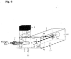
- Figure 6 is a drawing illustrating construction of an apparatus which is another example of the invention.
- Figure 7 is a graph showing variation with time of ion strength of o-chlorophenol and signal of detection system upon cutting laser beam (short period sample introduction ⁇ turbo-molecular pump exhaust) measured by using the apparatus of Figure 6.
- Figure 8 is a graph showing variation with time of ion strength of o-chlorophenol and signal of detection system upon cutting laser beam (short period sample introduction ⁇ oil diffusion pump exhaust).
- Figure 9 is a graph showing variation with time of ion strength of o-chlorophenol and signal of detection system upon cutting laser beam (conventional sample introduction ⁇ turbo-molecular pump exhaust).
- Figure 10 is a drawing illustrating construction of an apparatus which is another example of the invention.
- Figure 11 is a section of a sample introducing portion, a pulsed laser beam oscillator and a vacuum ionization chamber portion of the apparatus.
- Figure 12 is a graph showing mass spectra of chlorobenzene obtained by using the apparatus of Figure 10.
- Figure 13 is a drawing illustrating construction of an apparatus which is another example of the invention.
- Figure 14 is a section of a sample introducing portion, a slit skimmer, a pulsed laser beam oscillator and a vacuum ionization chamber portion of the apparatus.
- Figure 15 is a section of slit portion of two types slit skimmers used in the above apparatus.
- Figure 16 is a graph showing mass spectra of chlorobenzene obtained by using the apparatus of Figure 13.
- a nozzle or a pulse valve provided with an orifice capable of producing supersonic molecular jet is used.
- Pulse valves are used for fuel injection in engines, etc., and as described in "Jikken Kagaku Koza", 4th Ed., vol. 8, pp 127-129, 1993, in general, a plunger enforced on a sealing surface by a spring is attracted backward electromagnetically by applying an electric current in a moment to a solenoid (electromagnetic coil) located backward of the plunger, and the valve opens only for that time.
- Gentry-Giese type pulse valve and a pulse valve switching by using a piezo element have been developed, and these valves are also utilizable.
- the time since the time, while laser beam for ionization interacts with compound molecules to be measured, depends on the oscillation time of pulse laser beam, preferable pulse valves are those working in an extremely short time up to a similar degree to the oscillation time (irradiation time) of pulsed laser beam to be used.
- the lower limit is 0.1 ⁇ s or more, preferably 1 ⁇ s or more, more preferably 10 ⁇ s or more, particularly preferably 10 ⁇ s or more, and the upper limit is 5 ms or less, preferably 2 ms or less, more preferably 500 ⁇ s or less, particularly preferably 200 ⁇ s or less.
- the working time of the valve can be made shorter by lengthening the length of the spring and simultaneously raising the strength of spring, or by decreasing the electric resistance of the coil so that a great electric current can be applied and simultaneously raising working voltage.
- the size of the opening of the nozzle is designed so as to produce supersonic molecular jet. Although the size depends on the exhaust capacity of a vacuum ionization chamber, etc., about 0.01 to 1 mm 3 , particularly about 0.2 to 0.5 mm 3 as opening area is, in general, suitable.
- sample introduction may be either continuous introduction or pulse introduction, pulse introduction type is preferable in view of the load on exhaust system such as pump.
- Preferable valves are aforementioned ones.
- Respective pinhole nozzles may be mounted either on the same valve or the like or on separate valves or the like. That is, the valve or the like of a sample introducing portion may be one or plural.
- the size of the opening of each nozzle is designed so as to produce supersonic molecular jet. Although the size depends on exhaust capacity of a vacuum ionization chamber, etc., about 0.05 to 3 mm, particularly 0.1 to 1 mm as diameter is, in general, suitable.
- the distance between respective nozzles may be about 5 to 200 mm, usually about 20 to 50 mm. In the case that the number of nozzles is 3 or more, each nozzle may be arranged in straight or at random.
- the direction of the nozzles is preferably set so as to meat molecular jets ejected from respective nozzles in the range of from the front side of a ripeller electrode to an accelerating electrode, preferably around the ripeller electrode. That is, an important matter is that ionized molecules do not diffuse into space. For that purpose, it is necessary that the area of ionized molecules is as small as possible at the entrance of mass spectrometer, i.e. at the ripeller electrode. As an actual means, it is preferable so as to meet molecular jets ejected from 2 or more nozzles around the ripeller electrode.
- a skimmer may be not used.
- a skimmer is preferable because of decreasing disturbance of other molecular jet to a certain degree and of decreasing the load on the exhaust system of mass spectrometer.
- the skimmer is located so as to partition between the nozzle and the vacuum ionization chamber, so as to inhibit peripheral molecular jet stream from entering the vacuum ionization chamber, and so as to pass only the central portion of the molecular jet stream. Accordingly, the skimmer is, in principle, arranged so that the center of its opening is almost consistant with that of the opening of a nozzle.
- a suitable distance between the exhaust opening of the nozzle which forms molecular jet and the skimmer slit is about 2 to 300 mm, particularly about 7 to 100 mm.
- a suitable opening diameter of the skimmer is about 0.1 to 1 mm, particularly about 0.2 to 0.8 mm.
- the skimmer is projected toward sample introducing side.
- the skimmer isolates the vacuum ionization chamber so as not to pass except the opening.
- metals such as SUS and aluminum, glass, heat-resistant plastic and the like are usable.
- An exhaust means is provided which inhibits the molecular jet portion cut by the skimmer from entering the vacuum ionization chamber.
- the size of the slit of the slit nozzle is designed so as to produce supersonic molecular jet. Although the size depends on the exhaust capacity, etc., in general, it is about 0.01 to 1.0 mm, particularly about 0.1 to 0.8 mm in width, about 5 to 200 mm, particularly about 10 to 30 mm in length, and a ratio of width : length of about 1 : 1 to 1 : 1000, particularly about 1 : 10 to 1 : 300.
- As the mounting method of the nozzle there is an assembly composed of a slit nozzle and valves, i.e.
- a presser provided with a slit and a cord which seals the slit, rendered to work by 3 commercial pulse valve driving mechanisms, as disclosed in the aforementioned Review Science Instrumentation, vol. 67, pp 410-417, 1996. If the length is not so long, i.e. about 30 mm or less, the number of the driving mechanism can be one.
- a slit skimmer which partitions between the slit nozzle and the vacuum ionization chamber and inhibits peripheral portions of the stream of molecules of the molecular jet from entering the vacuum ionization chamber.
- the slit of the skimmer is designed so as to pass only the central portion of the molecular jet ejected from the nozzle of the sample introducing portion. Accordingly, the skimmer is, in principle, arranged so that the center of the slit is almost consistent with that of the slit of the nozzle.
- a suitable distance between the exhaust opening of the slit nozzle which forms molecular jet and the slit of the slit skimmer is about 3 to 30 mm, particularly about 7 to 25 mm.
- the width and length of the slit of the skimmer is preferably not shorter than the width and the length of that of the slit nozzle, and at the maximum, twice or less of that of the slit nozzle.
- a more preferable size is 1.2 to 1.5 times.
- a suitable size of the slit of the skimmer is about 0.01 to 1.2 mm, particularly about 0.1 to 1.0 mm in width, about 5 to 200 mm, particularly about 10 to 30 mm in length, and a ratio of width : length of about 1 : 4 to 1 : 1000, particularly about 1 : 10 to 1 : 150.
- the slit of the skimmer is formed on a planar skimmer or the slit is projected on the side of the vacuum ionization chamber, the effects of the invention are still exhibited. Nevertheless, it is preferable that the slit is projected on the sample introducing side, in view of not diffusing or disturbing by convergence or collision of the flow of the molecular jet which has passed the slit.
- Preferable projected forms are that both sides of the slit come close to each other from their bases toward the top of the slit in a form of straight or convex plane.
- a preferable angle between the center of the top of the slit and both bases of the slit is about 20 to 70 degrees, particularly about 40 to 50 degrees.
- the skimmer isolates the vacuum ionization chamber so as not to pass except the slit.
- metals such as SUS and aluminum, glass, heat-resistant plastic and the like are usable.
- An exhaust means is provided which inhibits the molecular jet portion cut by the slit skimmer from entering the vacuum ionization chamber.
- the pulsed laser beam oscillator may be any one capable of oscillating a high output pulsed laser beam.
- the oscillator oscillating nanosecond order pulsed laser beam the following ones can be used. That is, dye lasers are most commonly used. In the dye lasers, wavelength can be continuously varied from 330 to 1000 nm by using excimer laser or yag laser as a pumping light source, and exchanging laser dyes. Recently, light parametric oscillation laser was commercialized, and this laser can be used as the oscillator instead of dye laser. Generation region can be enlarged up to 220 nm by using multiple wave generation, mixing or the like of dye lasers.
- Femtosecond order laser beam can be oscillated by a system roughly composed of Xell excimer laser excited femtosecond pulsed dye laser and KrF excimer laser which is an amplifier.
- a nanosecond dye laser is quenched, and further, short cavity laser is excited.
- the excited laser passes a supersaturated absorber, and generates pulses of 9 pS.
- the pulsed beam is amplified by a dye amplifier, and is used as a pumping beam of distribution feedback type dye laser.
- femtosecond order pulsed laser beam having a wavelength in ultraviolet region and an output of about 20 mJ at the maximum is obtained.
- nanosecond order laser beam can be oscillated.
- ultrashort pulsed laser beam having a peak output of 1 MW or more oscillated by a pulsed laser beam oscillator.
- a preferable peak output is 10 MW to 100 GM, particularly preferably 100 MW to 10 GM.
- the peak output represents strength of laser beam, and is laser beam energy (J)/oscillation time (s).
- laser multiphoton ionization is a process of transferring a molecule of a compound to be measured from the ground state to an excitation state by a photon having an energy corresponding to the energy difference between the ground state and the excitation state, and then ionizing by the energy of photon.
- a preferable irradiation time is 3 times of the excitation life or less, more preferably twice or less, particularly preferably similar degree or less.
- the lower limit of preferable irradiation time is 1/10000 or more, more preferably 1/4000 or more, particularly preferably 1/2000 or more.
- preferable irradiation time is about 100 to 500 fs, more preferably 200 to 300 fs.
- a preferable pulsed laser beam energy is 5 mJ or less, more preferably 4 mJ or less, particularly preferably 3 mJ or less.
- a preferable lower limit is 1 mJ or more, more preferably 2 mJ or more.
- the wavelength of the laser beam to be irradiated preferably corresponds, in principle, to the energy difference between the intrinsic ground state and the intrinsic excitation state of each molecule to be measured, i.e. resonance wavelength.
- resonance wavelength the energy difference between the intrinsic ground state and the intrinsic excitation state of each molecule to be measured.
- ionization still occurs by non-resonance wavelength, and enough effects can be obtained.
- the condensation means of laser beam is not limited, and various forms can be used, such as conventional one having a circle beam section, planar one formed by using a special lens (cylindrical lens), etc.
- the irradiation position of laser beam is preferably prior to that the molecular jet is influenced by another molecular jet.
- the reason is, when the molecular jet meets another molecular jet, flow of molecules varies and/or molecular motion begins. Accordingly, to make molecular jet becomes meaningless, and moreover, the S/N ratio lowers.
- molecules become in a state of ion even if the ionized molecules interact with the molecules derived from another molecular jet to some degree, to lower the S/N ratio is rare.
- By mounting a skimmer only the molecules contributing to the signal of uniform flow of molecules can be taken out, and interference between molecular jets is delayed because of narrowing the diameter of the molecular jet. As a result, freedoms of irradiation point and form of laser beam are occasionally enlarged.
- the ionization chamber has a structure capable of forming high vacuum conditions, and is provided with a window which is made of a material capable of passing laser beam.
- the vacuum ionization chamber is occasionally connected with the vacuum chamber of a mass spectrometer without a partition. In such a case, the portion where ionization occurs corresponds to the vacuum ionization chamber.
- the mass spectrometer may be any type of time-of-flight type, quadropole type, double convergence type or so on.
- the ionization chamber, the mass spectrometer adjacent thereto and further the molecular jet ejecting portion isolated by a slit skimmer are rendered to maintain vacuum conditions of about 10 -6 to 10 -8 torr by connecting an oil rotary pump, a mechanical booster pump, an oil diffusion pump, a turbo-molecular pump or the like.
- the ionization chamber is evacuated by an oil-free turbo-molecular.
- the turbo-molecular pump has a structure where rotor disc blades provided with oblique slit(s) and fixed disc blades of which the direction of the slit(s) is opposite are arranged alternately, and in general, the inlet port is located on the upper side, the outlet port is located on the underside, and the shaft of the rotor blades is set vertically.
- the rotor blades rotate at a high speed (2000 to 7000 rpm) in a similar degree to the translational movement of molecules.
- the molecules collide with the rotor blade, and are struck down toward downstream side, and conveyed to the outlet port.
- the compression ratio (the ratio of exhaust pressure to intake pressure) is a measure of pump performance.
- the vacuum degree in the vacuum chamber is made about 10 -6 to 10 -8 torr by the turbo-molecular pump, and a pump having the capacity corresponding thereto is selected.
- turbo-molecular pump as the exhaust means of the vacuum chamber of the mass spectrometer.
- the sample introduction in general, since the ionization chamber (or corresponding portion thereto) or the front chamber, when using a skimmer, is maintained at a pressure of 10 -6 torr or less, around ordinary pressure is enough for the sample so long as it becomes gas, and the sample can be introduced by the pressure as a driving force. Accordingly, the sample may be not pressurized, but high pressure samples can also be introduced directly without problems. On the other hand, to reduce pressure is in some cases preferable, because of increasing the density of molecular jet which is well-known and improving sensitivity, although the degree is minor.
- the determination of mass number and detection of molecular ions can be conducted through the operation of a mass spectrometer under usual working conditions, and recorded by a usual digital oscilloscope, recorder.
- a laser ionization mass spectrometric apparatus shown in Figure 1 was prepared. Most of parts used for the apparatus were commercial goods. That is, a pulse valve made by General Valve Company (PN91-47-900 (85 kg/cm 2 )) was used for the sample introducing portion 1, a LPD 500 fs type laser system using dye laser made by Lambda Physik Company was used for the pulsed laser beam oscillator 2, a time-of-flight type mass spectrometer having a flight tube 450 mm in length was used for the mass spectrometer 4, a F 1094 type microchannel plate made by Hamamatsu Photonics Co., Ltd. was used for the detector 46, and a 9360 type digital oscilloscope made by Lecroy Company was used for the recorder (not illustrated). The opening of the nozzle 12 of the pulse valve 11 was a circular hole 0.8 mm in inside diameter.
- the vacuum chamber 40 of the mass spectrometer was evacuated by a UTM 150 type turbo-molecular pump made by Nippon Shinku Gijutsu Kabushiki Kaisha having an exhaust velocity of 190 l/s.
- the ionization chamber 3 by laser beam irradiation was evacuated by a ULK-06A type oil diffusion pump made by Nippon Shinku Gijutsu Kabushiki Kaisha having an exhaust velocity of 1200 l/s.
- the pulsed laser beam 22 generated from the oscillator 2 was condensed by the lens 21, and entered the vacuum ionization chamber 3 through the window 31.
- the sample gas was introduced intermittently by the pulse valve 11 of the sample introducing portion 1, and ejected from the nozzle 12 to form molecular jet 13.
- the molecular jet 13 entered the vacuum ionization chamber 3.
- the molecular jet 13 was radiated with the laser beam 22 and ionized there, and entered the mass spectrometer 4.
- the direction of the molecular jet was turned at 90 degrees by the ripeller electrode 42, and then, accelerated by the high voltage accelerating electrode 43.
- the molecular jet passed the ion passing hole 44 provided on the partition wall 41, and each ion was detected by the ion detector 46.
- the detection signal was measured by the digital oscilloscope.
- laser beam of 4 ns to 1 ps, 1 to 1000 MW was oscillated.
- the wavelength was 248 nm.
- Chlorobenzene was streamed together with argon gas at a constant concentration, and introduced into the vacuum ionization chamber in a molecular jet state through the pulse valve.
- Laser beam was irradiated with varying energy of 1 mJ and 4 mJ, peak output of 1 MW, 10 MW, 100 MW and 1000 MW, to induce.
- irradiation time of the laser beam was in the range of 1 ps to 4 ns.
- the pulsed laser beam was irradiated while synchronized with sample introduction.
- Produced ions were detected by the microchannel plate of the time-of-flight type mass spectrometer, and integrated 200 times by the digital oscilloscope to obtain spectra. The results are shown in Figure 2.
- Example 2 Using the same apparatus as Example 1, the same experiment as Example 1 was carried out except that the oscillation of the femtosecond laser portion was intercepted and pulsed laser beams having an energy of 1 mJ or 4 mJ and a peak output of 100 KW or 400 KW were irradiated (irradiation time : 10 ns). The results are shown in Figure 2.
- Example 1 Femtosecond order pulsed dye laser beam was oscillated by the LPD 500 fs type laser system made by Lambda Physik Company. The wavelength was 248 nm which was the same as Example 1.
- Chlorobenzene, bromobenzene or iodobenzene was introduced into the high vacuum ionization chamber together with argon gas as supersonic molecular jet at a constant concentration. Taking excitation life of each molecule into consideration, laser beam was irradiated for 500 fs, 150 fs with varying peak output and irradiation energy in the range of 0.2 to 1.5 mJ, to induce ionization. At that time, the peak output was 0.4 to 10 GW. Produced ions were detected by the microchannel plate of the time-of-flight type mass spectrometer, and integrated 200 times by the 9360 type digital oscilloscope made by Lecroy Company to obtain spectra. The results are shown in Figure 3, Figure 4 and Figure 5.
- Example 2 Using the same apparatus as Example 1, the same experiments as Example 2 were carried out except that the oscillation of the femtosecond laser portion was intercepted and pulsed laser beam of 15 ns was irradiated. The results are shown in Figure 3 to 5.
- the excitation life of chlorobenzene is 600 ps, and 500 fs, 150 fs, 15 ns of laser beam irradiation time correspond to 1/1200, 1/4000, 25 times, respectively.
- the excitation life of bromobenzene is 30 ps, and accordingly, correspond to 1/60, 1/200, 500 times, respectively.
- the excitation life of iodobenzene is reported to be about 400 fs, and accordingly, correspond to about 1/1.3, about 1/2.7, about 37500 times, respectively.
- Example 1 and Example 2 were carried out using the same apparatus under the same conditions except that peak output, irradiation time and energy of laser beam were varied, ion strength valves can be compared, although they are relative valves. Accordingly, it can be seen from Figure 2 and Figure 3 that ionization efficiency improves greater with increasing peak output by the energy so far as fragmentation of molecules does not occur. That is, the laser beam energy of 1 mJ and the irradiation time of 500 fs, 150 fs in Figure 3 correspond to peak output of 2 GW (2000 MW), 6, 7 GW (6700 MW). At that time, ion strength is read 1.5 and 1.7, respectively. Upon looking Figure 2, the ion strength at 1 mJ laser beam energy increases with increasing peak output, and is 1.4 at 1000 MW. It is apparent that ionization efficiency is improved by the increase of peak output.
- ionization efficiency is improved by the irradiation of ultrashort pulsed laser beam having a great peak output, but extreme fragmentation does not occur because irradiation energy does not become great due to short irradiation time. Accordingly, a high sensitivity detection is possible, and the lower limit of determination (detection) can be lowered.
- a laser ionization mass spectrometric apparatus shown in Figure 6 was prepared. Most of parts used for the apparatus were commercial goods. That is, a pulse valve made by General Valve Company (PN91-47-900 (85 kg/cm 2 )) was used for the sample introducing portion 1, a MOPO-730 type laser system made by General Valve Company was used for the pulsed laser beam oscillator 2, a reflectron time-of-flight type mass spectrometer having a flight tube 1200 mm in length was used for the mass spectrometer 4, a F 1094 type microchannel plate made by Hamamatsu Photonics Co., Ltd. was used for the detector 46, and a 9360 type digital oscilloscope made by Lecroy Company was used for the recorder (not illustrated). The opening of the nozzle 12 of the pulse valve 11 was a circular hole 0.8 mm in inside diameter.
- the vacuum chamber 40 and the ionization chamber 3 by laser beam irradiation of the mass spectrometer were evacuated by UTM 150 type turbo-molecular pump made by Nippon Shinku Gijutsu Kabushiki Kaisha having an exhaust velocity of 190 l/s.
- the pulsed laser beam 22 generated from the oscillator 2 was condensed by the lens 21, and entered the vacuum ionization chamber 3 through the window 31.
- the sample gas was introduced intermittently by the pulse valve 11 of the sample introducing portion 1, and ejected from the nozzle 12 to form molecular jet 13.
- the molecular jet 13 entered the vacuum ionization chamber 3.
- the molecular jet 13 was radiated with the laser beam 22 and ionized there, and entered the mass spectrometer 4.
- the direction of the molecular jet was turned at 90 degrees by the ripeller electrode 42, and then, accelerated by the high voltage accelerating electrode 43. Thereafter, the molecular jet passed the ion passing hole 44.
- the molecular jet was reflected by the ion reflector 45, and each ion was detected by the ion detector 46.
- the detection signal was measured by the digital oscilloscope.
- Used nanosecond order pulsed laser beam had a wavelength of 278.5 nm and a pulse width of 5 ns.
- the energy of the pulsed laser beam was 1 mJ.
- a definite amount of o-chlorophenol was dropped to a 500 ml flask where argon gas was streamed (initial concentration : about 200 ppm). The dropping rate was 1 time/20 minutes.
- the above pulse valve which was connected to the outlet of the flask in a form of dispensing a part of the discharge gas, was opened for 200 ⁇ s at a rate of 10 times/second, and o-chlorophenol was introduced into the high vacuum ionization chamber as supersonic molecular jet. Synchronizing therewith, pulsed laser beam was irradiated, and produced ions were detected by the microchannel plate of the time-of-flight type mass spectrometer. Spectra were obtained by the digital oscilloscope, and variation with time was recorded. Further, after 20 minutes from the termination of o-chlorophenol dropping, laser beam was cut. The results are shown in Figure 7.
- Example 3 As can be seen from the comparison of Example 3 with Comparative Examples 3, 4, according to the invention, since background caused by oil or residual sample can be reduced due to shortening of sample introduction time and using an oil-free pump for the exhaust of the ionization chamber, high sensitivity detection is possible and determination (detection) lower limit can be lowered.
- a laser ionization mass spectrometric apparatus shown in Figures 10-11 was prepared. Most of parts used for the apparatus were commercial goods. That is, a pulse valve made by General Valve Company (PN91-47-900 (85 kg/cm 2 )) was used for the sample introducing portion 1, a MOPO-730 type laser system made by General Valve Company was used for the pulsed laser beam oscillator 2, a reflectron time-of-flight type mass spectrometer having a flight tube 1200 mm in length was used for the mass spectrometer 4, a F 1094 type microchannel plate made by Hamamatsu Photonics Co., Ltd. was used for the detector 46, and a 9360 type digital oscilloscope made by Lecroy Company was used for the recorder (not illustrated).
- PN91-47-900 85 kg/cm 2
- MOPO-730 type laser system made by General Valve Company
- a reflectron time-of-flight type mass spectrometer having a flight tube 1200 mm in length was used
- the pulse valve 11 shown in Figure 11 was mounted on the sample introducing portion.
- the pulse valve was made of stainless steel, and two pinhole nozzles 12 having an opening diameter of 0.2 mm were provided apart from each other at a distance between there centers of 30 mm.
- the skimmer 14 was made of stainless steel having a thickness of 0.8 mm, a hole diameter of 0.3 mm, an outer wall angle of 55 degrees and inner wall angle of 45 degrees at the top.
- the position of the skimmer was 25 mm apart from the nozzle.
- Two same form nozzles and skimmers were located so that their molecular jets were met at an angle of 20 degrees so as to meet at the position of the ripeller electrode of the mass spectrometer, and the two nozzles were worked together while synchronized with laser beam.
- the pulsed laser beam 22 generated from the oscillator 2 was condensed by the lens 21, and entered the vacuum ionization chamber 3 through the window 31.
- the sample gas was introduced intermittently by the pulse valve 11 of the sample introducing portion 1, and ejected from the nozzle 12 to form molecular jet 13.
- the molecular jet 13 collided with the skimmer 14, and only the central portion passed the hole 15 of the skimmer 14, and entered the vacuum ionization chamber 3.
- the molecular jet 16 was irradiated with the laser beam 22 and ionized there, and entered the mass spectrometer 4.
- the irradiation direction of the laser beam 22 was in the same plane as the plane made by the 2 molecular jets, and was at a right angle to the symmetry axis of the 2 molecular jets.
- the direction of the molecular jet 16 was turned at 90 degrees by the ripeller electrode 42, and then, accelerated by the high voltage accelerating electrode 43.
- the molecular jet was reflected by the ion reflector 45 and each ion was detected by the ion detector 46.
- the detection signal was measured by the digital oscilloscope.
- the front chamber 17 isolated by the skimmer 14, the vacuum ionization chamber 3 and the vacuum chamber 40 of the mass spectrometer were connected to an exhaust system, respectively, and their insides were kept in vacuum conditions.
- Chlorobenzene was introduced into the high vacuum ionization chamber 4 together with argon gas at a definite concentration as supersonic jet. Produced ions were detected by the microchannel plate, and integrated 10 times by the digital oscilloscope to obtain spectra. The results are shown in Figure 12.
- Example 4 As can be seen from the comparison of Example 4 with Comparative Example 5, according to the invention, since a large amount of sample can be introduced without raising capacity of mass spectrometer, i.e. using an inexpensive compact mass spectrometer, sensitivity can be improved while a laser ionization mass spectrometric apparatus is kept compact.
- a laser ionization mass spectrometric apparatus shown in Figure 13-14 was prepared. Most of parts used for the apparatus were commercial goods. That is, a pulse valve made by General Valve Company (PN91-47-900 (85 kg/cm 2 )) was used for the sample introducing portion 1, a MOPO-730 type laser system made by General Valve Company was used for the pulsed laser beam oscillator 2, a reflectron time-of-flight type mass spectrometer having a flight tube 1200 mm in length was used for the mass spectrometer 4, a F 1094 type microchannel plate made by Hamamatsu Photonics Co., Ltd. was used for the detector 46, and a 9360 type digital oscilloscope made by Lecroy Company was used for the recorder (not illustrated).
- PN91-47-900 85 kg/cm 2
- MOPO-730 type laser system made by General Valve Company
- a reflectron time-of-flight type mass spectrometer having a flight tube 1200 mm in length was used for
- the slit nozzle 12 of the sample introducing portion was made of SUS, and the size of the slit opening was 0.1 mm ⁇ 10 mm.
- slit skimmers 14 having a section shown in Figure 15 were prepared.
- One of the angle between the center of the top of the slit and both bases of the slit was 40 degrees, and the other one was 50 degrees.
- the skimmers were made of aluminum having a maximum thickness of 1.2 mm.
- the top of the slit was sharpened, and the size of the opening of the slit 18 was 0.2 mm ⁇ 12 mm.
- the position of the slit skimmer 14 was 25 mm apart from the nozzle 12, and the nozzle 12 and the skimmer 14 were located so that the direction of the major axis and the center of them confirmed to each other.
- the pulsed laser beam 22 generated from the oscillator 2 was condensed by the lens 21, and entered the vacuum ionization chamber 3 through the window 31.
- the sample gas was introduced intermittently by the pulse valve 11 of the sample introducing portion 1, and ejected from the slit nozzle 12 to form molecular jet 13.
- the molecular jet 13 collided with the skimmer 14, and only the central portion passed the slit 18 of the skimmer 14, and almost only parallel streams entered the vacuum ionization chamber 3.
- the molecular jet 13 was irradiated with the laser beam 22 and ionized there, and entered the mass spectrometer 4.
- the direction of the molecular jet 16 was turned at 90 degrees by the ripeller electrode 42, and then, accelerated by the high voltage accelerating electrode 43. Thereafter, the molecular jet passed the ion passing hole 44, and reflected by the ion reflector 45, and then, each ion was detected by the ion detector 46. The detection signal was measured by the digital oscilloscope.
- the front chamber 17 isolated by the slit skimmer 14, the vacuum ionization chamber 3 and the vacuum chamber 40 of the mass spectrometer were connected to an exhaust system, respectively, and their insides were kept in vacuum conditions.
- Chlorobenzene was introduced into the high vacuum ionization chamber 3 together with argon gas at a definite concentration as supersonic jet. Produced ions were detected by the microchannel plate, and integrated 10 times by the digital oscilloscope to obtain spectra. The results are shown in Figure 16.
- Example 5 As can be seen from the comparison of Example 5 with Comparative Example 6, according to the invention, since a large amount of sample can be introduced without raising the capacity of mass spectrometer, i.e. by using an inexpensive compact mass spectrometer, the improvement in sensitivity can achieve with keeping a laser ionization mass spectrometer compact.
- ionization efficiency is improved by the irradiation of ultrashort pulsed laser beam having a great peak output, but extreme fragmentation does not occur because irradiation energy does not become great due to short irradiation time. Accordingly, a high sensitivity detection is possible, and the lower limit of determination (detection) can be lowered. Since background caused by oil or residual sample can be reduced due to shortening of sample introduction time and using an oil-free pump for the exhaust of the ionization chamber, high sensitivity detection is possible and determination (detection) lower limit can be lowered.
- the apparatus and method of the invention are suitable for rapid analysis of various compounds, such as nitrogen oxides, sulfur oxides, aromatic compounds, chlorine-containing organic compounds, chlorinated aromatic compounds and other halogen-containing compounds contained in combustion exhaust gases of coal, heavy oil, etc., combustion exhaust gases of municipal waste or industrial waste, gases generated by the pyrolysis of plastics and so on.
- various compounds such as nitrogen oxides, sulfur oxides, aromatic compounds, chlorine-containing organic compounds, chlorinated aromatic compounds and other halogen-containing compounds contained in combustion exhaust gases of coal, heavy oil, etc., combustion exhaust gases of municipal waste or industrial waste, gases generated by the pyrolysis of plastics and so on.
Landscapes
- Chemical & Material Sciences (AREA)
- Analytical Chemistry (AREA)
- Physics & Mathematics (AREA)
- Optics & Photonics (AREA)
- Engineering & Computer Science (AREA)
- Plasma & Fusion (AREA)
- Other Investigation Or Analysis Of Materials By Electrical Means (AREA)
- Electron Tubes For Measurement (AREA)
Applications Claiming Priority (9)
| Application Number | Priority Date | Filing Date | Title |
|---|---|---|---|
| JP228284/96 | 1996-08-29 | ||
| JP228283/96 | 1996-08-29 | ||
| JP8228284A JPH1069878A (ja) | 1996-08-29 | 1996-08-29 | レーザイオン化質量分析装置 |
| JP22828396A JP3765434B2 (ja) | 1996-08-29 | 1996-08-29 | レーザーイオン化質量分析装置 |
| JP8230866A JPH1074479A (ja) | 1996-08-30 | 1996-08-30 | レーザーイオン化質量分析装置及び質量分析方法 |
| JP230866/96 | 1996-08-30 | ||
| JP230867/96 | 1996-08-30 | ||
| JP8230867A JPH1074480A (ja) | 1996-08-30 | 1996-08-30 | レーザーイオン化法質量分析装置 |
| PCT/JP1997/003029 WO1998009316A1 (fr) | 1996-08-29 | 1997-08-29 | Spectroscope de masse a ionisation par laser et procede d'analyse par spectroscopie de masse |
Publications (1)
| Publication Number | Publication Date |
|---|---|
| EP0860859A1 true EP0860859A1 (fr) | 1998-08-26 |
Family
ID=27477321
Family Applications (1)
| Application Number | Title | Priority Date | Filing Date |
|---|---|---|---|
| EP97937847A Withdrawn EP0860859A1 (fr) | 1996-08-29 | 1997-08-29 | Spectroscope de masse a ionisation par laser et procede d'analyse par spectroscopie de masse |
Country Status (4)
| Country | Link |
|---|---|
| US (1) | US5977541A (fr) |
| EP (1) | EP0860859A1 (fr) |
| KR (1) | KR19990067163A (fr) |
| WO (1) | WO1998009316A1 (fr) |
Cited By (6)
| Publication number | Priority date | Publication date | Assignee | Title |
|---|---|---|---|---|
| WO2000058996A3 (fr) * | 1999-03-25 | 2001-04-19 | Gsf Forschungszentrum Umwelt | Dispositif d'admission de gaz destine a admettre un jet de gaz dirige et refroidi |
| WO2001051917A3 (fr) * | 2000-01-10 | 2002-04-04 | Mds Inc | Appareil et procede discriminants contre des especes ionisees non desirees en spectrometrie de masse avec des dispositifs de collision et de reaction |
| WO2001093305A3 (fr) * | 2000-05-31 | 2002-08-08 | Univ Johns Hopkins | Echantillonnage par laser pulse destine a un systeme de spectrometre de masse |
| AU757797B2 (en) * | 1999-10-26 | 2003-03-06 | Mitsubishi Heavy Industries, Ltd. | Method and apparatus for laser analysis of dioxins |
| CN102466655A (zh) * | 2010-11-16 | 2012-05-23 | 上海华质生物技术有限公司 | 一种微流控芯片与质谱联用检测装置及方法 |
| WO2018019837A1 (fr) * | 2016-07-26 | 2018-02-01 | Bundesrepublik Deutschand, Vertreten Durch Den Bundesminister Für Wirtschaft Und Energie, Dieser Vertreten Durch Den Präsidenten Der Bundesanstalt Für Materialforschung Und -Prüfung (Bam) | Dispositif d'analyse d'échantillons gazeux et procédé de mise en évidence d'analytes dans un gaz |
Families Citing this family (13)
| Publication number | Priority date | Publication date | Assignee | Title |
|---|---|---|---|---|
| DE19822674A1 (de) * | 1998-05-20 | 1999-12-09 | Gsf Forschungszentrum Umwelt | Gaseinlaß für eine Ionenquelle |
| AUPR474801A0 (en) * | 2001-05-03 | 2001-05-31 | University Of Sydney, The | Mass spectrometer |
| US20040036018A1 (en) * | 2001-06-06 | 2004-02-26 | Yoshihiro Deguchi | Device and method for detecting trace amounts of organic components |
| US6703610B2 (en) | 2002-02-01 | 2004-03-09 | Agilent Technologies, Inc. | Skimmer for mass spectrometry |
| JP2006003167A (ja) | 2004-06-16 | 2006-01-05 | Shimadzu Corp | 生体試料分析用質量分析装置 |
| JP5604165B2 (ja) * | 2010-04-19 | 2014-10-08 | 株式会社日立ハイテクノロジーズ | 質量分析装置 |
| WO2014063246A1 (fr) * | 2012-10-26 | 2014-05-01 | Fluidigm Canada Inc. | Analyse d'un échantillon par cytométrie de masse |
| CN113851230B (zh) * | 2020-06-28 | 2023-06-13 | 核工业西南物理研究院 | 一种聚变超声分子束加料强束流聚束装置 |
| CN113340972B (zh) * | 2021-05-06 | 2023-11-21 | 清华大学 | 基于快速压缩机的超快时间分辨质谱诊断系统 |
| US11667992B2 (en) | 2021-07-19 | 2023-06-06 | Agilent Technologies, Inc. | Tip for interface cones |
| CN114280005A (zh) * | 2021-12-28 | 2022-04-05 | 中国工程物理研究院材料研究所 | 一种氢及氢同位素的快速分析检测装置及方法 |
| EP4706078A1 (fr) * | 2023-05-02 | 2026-03-11 | Agilent Technologies, Inc. | Transport basé sur l'advection de matériau ablaté |
| KR102822876B1 (ko) * | 2023-05-22 | 2025-06-18 | 강원대학교산학협력단 | 고분해능 진공 자외선 질량분석 문턱 이온화 질량 분광계 |
Family Cites Families (3)
| Publication number | Priority date | Publication date | Assignee | Title |
|---|---|---|---|---|
| CA2101237C (fr) * | 1992-09-11 | 1999-04-13 | Stephen Ward Downey | Appareil muni d'un spectrometre de masse |
| US5631462A (en) * | 1995-01-17 | 1997-05-20 | Lucent Technologies Inc. | Laser-assisted particle analysis |
| JPH08203468A (ja) * | 1995-01-27 | 1996-08-09 | Hitachi Ltd | 大気圧イオン化質量分析計 |
-
1997
- 1997-08-29 EP EP97937847A patent/EP0860859A1/fr not_active Withdrawn
- 1997-08-29 US US09/065,089 patent/US5977541A/en not_active Expired - Fee Related
- 1997-08-29 KR KR1019980703112A patent/KR19990067163A/ko not_active Ceased
- 1997-08-29 WO PCT/JP1997/003029 patent/WO1998009316A1/fr not_active Ceased
Non-Patent Citations (1)
| Title |
|---|
| See references of WO9809316A1 * |
Cited By (10)
| Publication number | Priority date | Publication date | Assignee | Title |
|---|---|---|---|---|
| WO2000058996A3 (fr) * | 1999-03-25 | 2001-04-19 | Gsf Forschungszentrum Umwelt | Dispositif d'admission de gaz destine a admettre un jet de gaz dirige et refroidi |
| US6772649B2 (en) | 1999-03-25 | 2004-08-10 | GSF-Forschaungszenfrum für Umwelt und Gesundheit GmbH | Gas inlet for reducing a directional and cooled gas jet |
| AU757797B2 (en) * | 1999-10-26 | 2003-03-06 | Mitsubishi Heavy Industries, Ltd. | Method and apparatus for laser analysis of dioxins |
| US6573493B1 (en) | 1999-10-26 | 2003-06-03 | Mitsubishi Heavy Industries, Ltd. | Method and apparatus for laser analysis of dioxins |
| WO2001051917A3 (fr) * | 2000-01-10 | 2002-04-04 | Mds Inc | Appareil et procede discriminants contre des especes ionisees non desirees en spectrometrie de masse avec des dispositifs de collision et de reaction |
| WO2001093305A3 (fr) * | 2000-05-31 | 2002-08-08 | Univ Johns Hopkins | Echantillonnage par laser pulse destine a un systeme de spectrometre de masse |
| US6734423B2 (en) | 2000-05-31 | 2004-05-11 | The Johns Hopkins University | Pulsed laser sampling for mass spectrometer system |
| CN102466655A (zh) * | 2010-11-16 | 2012-05-23 | 上海华质生物技术有限公司 | 一种微流控芯片与质谱联用检测装置及方法 |
| CN102466655B (zh) * | 2010-11-16 | 2015-12-16 | 上海华质生物技术有限公司 | 一种微流控芯片与质谱联用检测装置及方法 |
| WO2018019837A1 (fr) * | 2016-07-26 | 2018-02-01 | Bundesrepublik Deutschand, Vertreten Durch Den Bundesminister Für Wirtschaft Und Energie, Dieser Vertreten Durch Den Präsidenten Der Bundesanstalt Für Materialforschung Und -Prüfung (Bam) | Dispositif d'analyse d'échantillons gazeux et procédé de mise en évidence d'analytes dans un gaz |
Also Published As
| Publication number | Publication date |
|---|---|
| WO1998009316A1 (fr) | 1998-03-05 |
| KR19990067163A (ko) | 1999-08-16 |
| US5977541A (en) | 1999-11-02 |
Similar Documents
| Publication | Publication Date | Title |
|---|---|---|
| US5977541A (en) | Laser ionization mass spectroscope and mass spectrometric analysis method | |
| Galloway et al. | Pathways and kinetic energy disposal in the photodissociation of nitrobenzene | |
| Huber et al. | Laser–ion coaxial beams spectrometer | |
| Chen et al. | Photofragmentation of ketene to CH2 (~ X3B1)+ CO. 1. Barrier height and dissociation rate constant | |
| Walter et al. | Spectroscopy of the benzene cation: Resonance-enhanced multiphoton dissociation spectra of the B̃ (E2g)← X̃ (E1g) transition | |
| Rockney et al. | Resonant multiphoton ionization detection of the NO2 fragment from infrared multiphoton dissociation of CH3NO2 | |
| Ni et al. | Photodissociation of propyne and allene at 193 nm with vacuum ultraviolet detection of the products | |
| Carrington et al. | Laser-induced predissociation spectrum of O2+ in an ion beam | |
| Buzza et al. | Femtosecond excitation dynamics of acetone: Dissociation, ionization, and the evolution of multiply charged elemental species | |
| Lubman et al. | Isotopically selective resonant two-photon ionization in supersonic beams | |
| Schmid et al. | Photodissociation of rovibrationally excited C 2 H 2: Observation of two pathways | |
| Buck et al. | Infrared photodissociation of size selected internally excited ethylene clusters | |
| Kolodney et al. | NO (X 2Π) product state distributions in molecule–surface collision‐induced dissociation: Direct inelastic scattering of n, i‐C3F7NO from MgO (100) at E incident≤ 7.0 eV | |
| Melchior et al. | The photodissociation of ground and vibrationally excited halogenated alkanes | |
| Armstrong et al. | Multiphoton ionization of uranium hexafluoride | |
| Jen et al. | Production of HCO from propenal photolyzed near 300 nm: Reaction mechanism and distribution of internal states of fragment HCO | |
| Philis | Laser induced ionisation/dissociation of cyclopentanone in the 320–370 nm region | |
| Price et al. | Time‐of‐flight measurements of single rovibrational states of carbon monoxide | |
| Makarov et al. | Selective infrared multiphoton dissociation of molecules in a pulsed gasdynamic flow of small extent | |
| JP3765434B2 (ja) | レーザーイオン化質量分析装置 | |
| Syage et al. | Resonance ion dissociation spectroscopy of CH3I+ produced by molecular beam electron-impact ionization | |
| Ridley et al. | The field-ionization of near-dissociation ion-pair states of I 2 | |
| Linnartz | Planar plasma expansions as a tool for high resolution molecular spectroscopy | |
| JPH1074479A (ja) | レーザーイオン化質量分析装置及び質量分析方法 | |
| CN1206493A (zh) | 激光离子化质量分析装置及质量分析方法 |
Legal Events
| Date | Code | Title | Description |
|---|---|---|---|
| PUAI | Public reference made under article 153(3) epc to a published international application that has entered the european phase |
Free format text: ORIGINAL CODE: 0009012 |
|
| 17P | Request for examination filed |
Effective date: 19980519 |
|
| AK | Designated contracting states |
Kind code of ref document: A1 Designated state(s): DE |
|
| STAA | Information on the status of an ep patent application or granted ep patent |
Free format text: STATUS: THE APPLICATION IS DEEMED TO BE WITHDRAWN |
|
| 18D | Application deemed to be withdrawn |
Effective date: 20040301 |