EP0860874A2 - Dispositif de refroidissement et installation de traitement d'informations utilisant celui-ci - Google Patents
Dispositif de refroidissement et installation de traitement d'informations utilisant celui-ci Download PDFInfo
- Publication number
- EP0860874A2 EP0860874A2 EP97310675A EP97310675A EP0860874A2 EP 0860874 A2 EP0860874 A2 EP 0860874A2 EP 97310675 A EP97310675 A EP 97310675A EP 97310675 A EP97310675 A EP 97310675A EP 0860874 A2 EP0860874 A2 EP 0860874A2
- Authority
- EP
- European Patent Office
- Prior art keywords
- heat sink
- heating element
- cooling fan
- heat
- fan
- Prior art date
- Legal status (The legal status is an assumption and is not a legal conclusion. Google has not performed a legal analysis and makes no representation as to the accuracy of the status listed.)
- Granted
Links
Images


Classifications
-
- H—ELECTRICITY
- H10—SEMICONDUCTOR DEVICES; ELECTRIC SOLID-STATE DEVICES NOT OTHERWISE PROVIDED FOR
- H10W—GENERIC PACKAGES, INTERCONNECTIONS, CONNECTORS OR OTHER CONSTRUCTIONAL DETAILS OF DEVICES COVERED BY CLASS H10
- H10W40/00—Arrangements for thermal protection or thermal control
- H10W40/40—Arrangements for thermal protection or thermal control involving heat exchange by flowing fluids
- H10W40/43—Arrangements for thermal protection or thermal control involving heat exchange by flowing fluids by flowing gases, e.g. forced air cooling
-
- G—PHYSICS
- G06—COMPUTING OR CALCULATING; COUNTING
- G06F—ELECTRIC DIGITAL DATA PROCESSING
- G06F1/00—Details not covered by groups G06F3/00 - G06F13/00 and G06F21/00
- G06F1/16—Constructional details or arrangements
- G06F1/20—Cooling means
Definitions
- the present invention relates to a heat sink. More particularly, the present invention relates to a heat sink used for cooling an integrated circuit package, which generates heat, such as a microprocessor unit (MPU) incorporated into electronic equipment.
- MPU microprocessor unit
- the degree of integration is enhanced so as to enhance the function of the integrated circuit and increase the processing speed. Therefore, the quantity of heat generated in the integrated circuit has been increased. Accordingly, the inside of the casing of a personal computer is forcibly cooled by a cooling fan, and the MPU is located at a position where the cool air of the cooling fan flows, and a heat sink provided with a large number of fins is fixed to the MPU so that the MPU can be forcibly air-cooled.
- an MPU of a higher performance is now required for a personal computer. An MPU of a higher performance generates a quantity of heat larger than that generated by other electronic parts.
- Figs. 15A ⁇ C are views showing a heat sink described in Japanese Unexamined Patent Publication No. 62-49700 which is used as a local cooling means.
- Fig. 15A is a plan view which is taken from the upper surface side
- Fig. 15B is a cross-sectional view taken at the one-dotted chain line ABCD shown in Fig. 15A
- Fig. 15C is a plan view taken in the direction of arrow Z in Fig. 15B.
- this heat sink is composed in such a manner that a motor 2a, which is a drive section for blades 2b, is attached to the main body 1 of the heat sink, and fins 1a are perpendicularly arranged so that they surround the blades 2b.
- the main body 1 of the heat sink is fixed to a heating element 3 such as a power transistor. Heat generated in the heating element is conducted to a bottom portion of the main body of the heat sink and further conducted to the fins 1a.
- the motor 2a is driven, the blades 2b are rotated, so that cooling air is sucked from an upper portion of the cooling fan 2.
- the cooling air to which a centrifugal force is given by the rotation of the blades 2b cools the upper portions of the fins 1a, and the cooling air blown out downward by the blades 2b cools lower portions of the fins 1a. In this way, the cooling air which has been sucked from the upper portion passes through the fins 1a is discharged into the periphery of the heat sink. Therefore, the main body 1 of the heat sink can be cooled and further the heating element 3 can be cooled.
- Fig. 16 is a view showing the heat sink described in Japanese Unexamined Patent Publication (PCT route) No. 8-502804.
- PCT route Japanese Unexamined Patent Publication
- a plurality of perpendicular fins 1a In the overall periphery of the main body 1 of the heat sink, there are provided a plurality of perpendicular fins 1a, and the cooling fan 2 is supported by the main body 1 of the heat sink.
- the motor is arranged inside the blades 2b, the height of the cooling fan 2 in the axial direction is reduced, and when a portion of the cooling fan 2 intrudes into the main body of the heat sink, the thickness of the fan body 5 is reduced.
- the cooling fan 2 When the cooling fan 2 is driven, the blades 2b are rotated, so that a cooling air can be sucked from the upper portion.
- the thus sucked cooling air cools the bottom portion of the main body 1 of the heat sink and passes through among the fins 1a. Therefore, the cooling air absorbs the heat which has been conducted from the main body 1 of the heat sink to the fins 1a, and the absorbed heat is dissipated to the periphery of the heat sink.
- this heat sink is fixed to a heating element such as an MPU, the heating element can be locally cooled.
- Fig. 17A and 17B are views showing the heat sink described in Japanese Unexamined Patent Publication No. 6-268125.
- Fig. 17A is a plan view which is taken from the upper surface.
- Fig. 17B is a cross-sectional view taken on line B - B in Fig. 17A.
- the motor 2a of the cooling fan 2 is fixed to the bottom portion of the main body 1 of the heat sink, and cooling fins 1a are perpendicularly arranged in such a manner that they surround the cooling fan 2.
- the bottom portion of the main body 1 of the thus composed heat sink is fixed to a heating element 3 such as an MPU.
- the blades 2b are rotated, so that a cooling air can be sucked from the upper portion.
- the sucked cooling air passes through among the fins 1a and discharges into the periphery of the heat sink.
- the heating element 3 can be cooled via the main body 1 of the heat sink.
- the motor 2a which drives the cooling fan 2 is directly fixed to the bottom portion of the main body 1 of the heat sink.
- ball bearings or sleeve bearings are used, and lubricant such as grease or oil is charged in the bearing. Due to the above structure, heat is directly transmitted to the bearing from the bottom portion of the main body 1 of the heat sink located close to the heating element 3. Accordingly, the temperature of the bearing is raised. When the temperature of the bearing is raised, the deterioration of the grease or oil is facilitated, and the life of the motor 2a is shortened.
- the cooling fan 2 is mounted on the upper portion. Accordingly, areas of the fins 1a arranged on the side are small. Therefore, in order to realize a sufficiently high cooling performance, it is necessary to provide small fins with very small intervals between the fins. In order to realize the small fins 1a, the manufacturing cost is increased in the cutting process. Further, since the intervals between the fins 1a are very small, blocking tends to occur when dust gathers between the fins 1a. Accordingly, a quantity of cooling air is lowered, and the cooling performance is deteriorated.
- a first aspect of the invention provides a heat sink comprising a box composed of a bottom surface coming into contact with a heating element (e.g.,MPU), a side on which ventilation holes are formed and an upper surface on which a cooling fan having at least blades and a motor is embedded and fixed.
- a heating element e.g.,MPU
- MPU heating element
- the performance can be easily optimized, and when the upper surface is provided on the box and the cooling fan is fixed onto the upper surface, the area of the side of the box can be sufficiently ensured, and further the deterioration of lubricant in the motor bearing can be prevented.
- An embodiment of the first aspect provides a heat sink in which the bottom surface is larger than a heat transmitting section coming into contact with the heating element, and ventilation holes are formed at positions on the bottom surface different from the position of the heat transmitting section. Due to the above structure, a change in the design of the hole can be performed in a wide range. Therefore, it becomes easy to optimize the performance. Further, the cooling performance can be enhanced and the noise generated by the cooling fan can be decreased.
- a further embodiment of the first aspect provides a heat sink in which the ventilation holes formed on the bottom surface are open under the condition that the heat transmitting section comes into contact with the heating element. Due to the above structure, the quantity of cooling air passing through in the holes formed on the bottom surface of the box is increased, so that the performance of cooling the bottom surface of the box can be enhanced. Compared with a case in which holes are formed only on the side, the cooling air can flow smoothly. Therefore, the occurrence of noise can be decreased.
- a second aspect of the invention provides a heat sink comprising: a box composed of a bottom surface coming into contact with a heating element, a side on which ventilation holes are formed and an upper surface, the bottom surface having a heat transmitting section coming into contact with the heating element and also having ventilation holes; and a cooling fan composed of blades and a motor, wherein the cooling fan is embedded in the upper surface.
- An embodiment of the second aspect provides a heat sink in which a radiating member is arranged between the cooling fan and the bottom surface of the box, and a portion of the radiating member is fixed onto the bottom surface. Due to the above structure, surface areas of the radiating fins are added to the surface area of the box. Therefore, the cooling performance can be enhanced.
- a further embodiment of the second aspect provides a heat sink in which the dimensions of the box are larger than those of the heating element and are made to coincide with the outside dimensions of a socket holding the heating element, and the center of the cooling fan is located eccentric with respect to the center of the heating element. Due to the above structure, it is possible to fix the box to the socket. Even if the rotational center of the cooling fan is different from the heating center of the heating element, it is unnecessary to change the design of the holes on the side and also it is unnecessary to correct the design. Since the center of each component is different, it is possible to cool a portion of high temperature at the heating center by the strongest air flow sent out from the blades of the cooling fan. Accordingly, the cooling performance can be enhanced.
- a third aspect of the invention provides a heat sink comprising: a heat sink component having a bottom surface coming into contact with a heating element; a cooling fan having at least blades and a motor and a cover for fixing the fan to the heat sink component, wherein the cover is used for setting a distance so that a distance from the bottom surface of the cover at the end of the heat sink component to the upper surface of the heat sink component can be smaller than a distance from the bottom surface of the cover immediately below the fan to the upper surface of the heat sink component. Due to the above structure, it is possible to minimize the deterioration of the cooling performance without increasing the intensity of noise.
- a fourth aspect of the invention provides a heat sink comprising: a heat sink component having a bottom surface coming into contact with a heating element; a cooling fan having at least blades and a motor; and a cover for fixing the fan to the heat sink component, wherein the cover can be opened and closed round a hinge arranged at one end of the cover and locked at the other end. Due to the above structure, it is possible to conduct working on the heating element without removing the cover and the fan. That is, when the heat sink component to which the fan is attached is fixed to the heating element, it is possible to expose a hole for fixing the heat sink component by disengaging the lock of the cover and opening and closing it. Accordingly, it can be screwed and fixed there.
- a fifth aspect of the invention provides a heat sink comprising: a rectangular heat sink component having a bottom surface coming into contact with a heating element; a cooling fan having at least blades and a motor and a cover for fixing the fan to the heat sink component, wherein a heat conveyance member for diffusing heat is attached to the base of the heat sink component. Due to the above structure, the temperature at the end portion is not lowered, that is, the temperature of the overall heat sink can be made uniform. Accordingly, the cooling performance can be enhanced. The reason why the temperature of the overall heat sink can be made uniform is described as follows. In the case of a heat sink, the shape of which is rectangular, a quantity of heat transmitted in the longitudinal direction is decreased.
- a sixth aspect of the invention provides an information processor comprising: a heat sink component having a bottom surface coming into contact with a heating element; a cooling fan having at least blades and a motor; and a cover for fixing the fan to the heat sink component, wherein a heat conveyance member is attached to the base of the heat sink component so as to convey heat to another cooling section. Due to the above structure, even if a quantity of heat generated by the heating element is increased, it is possible to incorporate the heat sink having the fan into the mounting space used presently. Up to this time, when the heat sink having the fan is incorporated into a limited mounting space, it is impossible to increase the volume of the heat sink and the capacity of the cooling fan in the case of an increase in the quantity of heat generated by the heating element when the processing speed is raised. However, according to the sixth aspect of the invention, the heat conveyance member is arranged in the heat sink, and the increased heat is conveyed to another cooling unit by the heat conveyance member.
- a seventh aspect of the invention provides an information processor comprising: a heat sink component having a bottom surface coming into contact with a heating element; a heating element; and a printed circuit board, wherein the heat sink component and the cooling fan are fixed onto the printed circuit board by a bracket for fixing the heat sink having a cooling fan utilizing a hole for fixing the cooling fan. Due to the above structure, the hole for fixing the cooling fan is used. Therefore, while it is unnecessary to conduct an additional machining, the heat sink and the cooling fan can be attached to the printed circuit board of the apparatus. Accordingly, the occurrence of vibration and shock can be prevented at a low cost.
- Figs. 1A and 1B are views showing the first embodiment of the present invention together with an MPU which is a heating element.
- Fig. 1A is a perspective view showing a heat sink together with an MPU
- Fig. 1B is a cross-sectional view taken on a line passing through the center of the heat sink shown in Fig. 1A in which the heat sink is fixed to an MPU.
- the heat sink of the first embodiment of the invention comprises a box 10 and a cooling fan 11 arranged in the ceiling section of the box 10.
- the box 10 is made of good heat conducting material, and the bottom of the box 10 is formed into a heat transmitting section which comes into contact with a heating element 12.
- On the side walls of the box 10 there are provided a plurality of ventilation holes 13.
- a cooling fan composed of blades 11b and a motor 11a to rotate the blades 11b. This cooling fan is fixed onto the ceiling surface of the box 10 by means of screws or adhesion.
- examples of a good heat conducting material composing the box 10 are: metal such as aluminum, and plastics such as resin, the brand name of which is Amoco Xydar manufactured by Wake Field Engineering Co., into which carbon fibers are mixed.
- metal such as aluminum
- plastics such as resin, the brand name of which is Amoco Xydar manufactured by Wake Field Engineering Co., into which carbon fibers are mixed.
- metal a method of sheet metal forming or of aluminum die casting is used.
- plastics the method of injection molding is used.
- Shapes of the ventilation holes formed on the side wall of the box 10 may be circular, triangular or polygonal. While consideration is given to air speed, heat transmission and noise, the best position and the number of holes are determined. According to an experiment carried out by the inventors, the best result was obtained when the total area of the ventilation holes 13 was approximately 15% of the total area of the sides of the box 10.
- the main body of the heat sink is formed into a box-shape. Therefore, it becomes possible to extend the wall surface of the heat sink to the ceiling surface and the side surface portion in which the cooling fan is arranged, that is, it becomes possible to ensure sufficiently large fin areas. For this reason, it is unnecessary to provide cooling fins of complicated shapes, so that the fins can be manufactured at a low cost. Since the motor of the cooling fan is arranged at the ceiling portion distant from an MPU, the bearing of the fan is not exposed to high temperatures. Accordingly, the deterioration of lubricant charged into the bearing can be prevented, and the reliability can be enhanced.
- Fig. 2 is a view showing the second embodiment of the present invention together with an MPU.
- the structure of the second embodiment is substantially the same as that of the first embodiment. The different points are described below.
- the bottom portion of the box 10 is formed larger than the outer shape of an MPU 12 to be cooled; the heat transmitting section 15 is made smaller than the bottom surface of the box 10; and a plurality of ventilation holes 14 are also formed in a portion of the bottom surface protruding from the MPU 12. According to an experiment done by the inventors, it was possible to provide a good result when the total area of the ventilation holes 14 formed on the bottom surface of the box 10 was approximately 20% of the area of the bottom surface of the box. As a result, it is preferable that the total area of the holes formed on the sides and the bottom surface of the box 10 is approximately 15 to 20% of the total area of the sides and the bottom surface of the box 10.
- the radiating area of the box of the second embodiment is larger than that of the first embodiment. Accordingly, the radiating performance of the second embodiment can be enhanced. Concerning other points, the second embodiment can provide the same effect as that of the first embodiment.
- Figs. 3A and 3B are views showing the third embodiment of the present invention together with an MPU.
- Fig. 3A is a perspective view
- Fig. 3B is a schematic cross-sectional view.
- the structure of the third embodiment is substantially the same as that of the second embodiment.
- the heat transmitting section 15 of the box 10 protrudes from the bottom surface of the box.
- This protruding portion can be formed as follows. A plate made of a good heat conducting material is machined to a predetermined size and fixed onto the bottom surface of the box 10 by means of adhesion, soldering or calking. Alternatively, in the manufacturing process in which the box 10 is formed by means of sheet metal forming, aluminum die casting or injection molding, this protruding portion is formed from the same material as that of the box.
- the heat transmitting section 15 is contacted with an MPU 12 as shown in Fig. 3B.
- air is sucked into the box from the upper surface of the cooling fan 11.
- the sucked air is discharged from the ventilation holes 13 formed on the sides of the box 10 and the ventilation holes 14 formed on the bottom surface.
- the air discharged from the ventilation holes 14 formed on the bottom surface passes through between the bottom surface of the box 10 and the heating element 12 and discharges outside. Heat generated by the MPU is transmitted to the box 10 via the heat transmitting section 15 and radiates into air.
- the cooling area can be increased, and the cooling performance can be enhanced.
- other points are the same as those of the first embodiment.
- Figs. 4A, 4B and 4C are views showing the fourth embodiment of the present invention.
- Fig. 4A is a schematic cross-sectional view
- Fig. 4B is a schematic cross-sectional view of the conventional heat sink shown for the purpose of comparison
- Fig. 4C is a schematic illustration showing the operation of this embodiment.
- the structure of the fourth embodiment is substantially the same as that of the first embodiment.
- One different point is that ventilation holes are formed on the sides of the air gap portion S arranged in parallel with the cooling fan 11.
- Figs. 5A and 5B are views showing the fifth embodiment of the present invention.
- Fig. 5A is a cross-sectional view
- Fig. 5B is a perspective view showing a radiating member.
- the structure of the fifth embodiment is substantially the same as that of the first embodiment.
- a radiating member 16 having ventilation holes 17 is arranged on the inner surface of the bottom of the box 10.
- This radiating member 16 is made of a good heat conducting material such as metal or plastic, and it is formed into a fin-shape in which a disk and a circular cone are combined as shown in Fig. 5B. In the fin portion, there are provided a plurality of holes 17.
- Figs. 6A and 6B are perspective views showing another example of the radiating member of the fifth embodiment. Both Figs. 6A and 6B show other examples of the radiating member.
- the radiating member may be formed into a shape shown in Fig. 6A in which the inclined fins are extended in all directions.
- the radiating member may be formed into a shape shown in Fig. 6B in which the horizontal fins are extended in the transverse direction.
- other shapes may be adopted as long as the air speed, heat transmission and noise are well balanced.
- the radiating area is increased as the radiating member 16 is provided. Accordingly, the cooling performance of the fifth embodiment is higher than that of the first embodiment. In this connection, the effect of the fifth embodiment is the same as that of the first embodiment.
- Figs. 7A and 7B are views showing the sixth embodiment of the present invention.
- Fig. 7A is a perspective view showing the heat sink together with an MPU mounted on the socket.
- Fig. 7B is a view for explaining the effect of the eccentric fan.
- a socket 18 to which the MPU 12 can be easily attached and from which the MPU 12 can be easily detached, and when the heat sink is used, the terminals of the MPU 12 can be connected to the socket 18 under pressure so as to attain a positive connection.
- the socket 18 requires a redundant space in one direction of the MPU 12. Therefore, the size of the socket 18 is larger than that of the MPU 12.
- the center O 1 of the cooling fan 11 can be arranged at a position eccentric to the center O 2 of the MPU 12 by a distance W when the box 10 is formed into a size which is substantially the same as the size of the socket 18. Since the center of the box 10 is eccentric to the center of the MPU 12, the center of the heat transmitting section 15 is also eccentric to the center.
- Curve A is a temperature distribution curve of the MPU 12. At the middle of the temperature distribution curve, the temperature is the highest. In the case of no eccentricity, the cooling fan 11 is located at point B, however, in the case of eccentricity of this embodiment, the cooling fan 11 is located at point C. Therefore, in this embodiment, the strongest wind sent out from the blades 11b of the cooling fan 11 is made to blow against the bottom portion of the box 10 which comes into contact with the high temperature portion of the heating element 12. Consequently, the cooling performance can be enhanced. In this connection, other effects provided by the sixth embodiment are the same as those of the first embodiment.
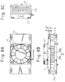
- Figs. 8A, 8B, and 8C and 9 are views showing the seventh embodiment of the present invention.
- Fig. 8A is a plan view
- Fig. 8B is a front view
- Fig. 8C is a side view
- Fig. 9 is an exploded perspective view.
- the seventh embodiment is composed of a heat sink main body 20, cover 21 and cooling fan 22.
- the heat sink main body 20 is composed in such a manner that a large number of radiating fins 20b are perpendicularly arranged on the base 20a.
- the heat sink main body 20 is made of metal, the heat conductivity of which is high, such as aluminum or aluminum alloy by means of extrusion or cold forging.
- the heat sink main body 20 is made of resin, the heat conductivity of which is high.
- Distance A from the bottom surface of the cover at the end portion of the heat sink main body to the upper surface of the heat sink main body is smaller than distance B from the bottom surface of the cover immediately below the fan to the upper surface of the heat sink main body 20.
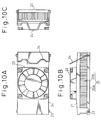
- Figs. 10A, 10B, and 10C are views showing the eighth embodiment of the present invention.
- Fig. 10A is a plan view
- Fig. 10B is a front view
- Fig. 10C is a side view.
- the structure of this eighth embodiment is substantially the same as that of the seventh embodiment described above.
- One different point is a method of connecting the heat sink main body 20 with the cover 21.
- the connecting method of this embodiment is described as follows.
- One end of the cover 21 is connected with the heat sink main body 20 by a hinge pin 23, and the other end is fixed by a spring made of a wire.
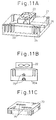
- Figs. 11A, 11B, and 11C are views showing the ninth embodiment of the present invention.
- Fig. 11A is a perspective view
- Fig. 11B is a cross-sectional view
- Fig. 11C is a rear view.
- the structure of the ninth embodiment is composed of a rectangular heat sink main body 20 of which the bottom surface comes into contact with the heating element, a cover 21 and a cooling fan 22.
- the heat sink main body 20 and the cover 21 are made of the same material as that of the aforementioned embodiment.
- a heat conveyance member 25 composed of a heat pipe made of metal of good heat conductivity on the upper surface, bottom surface or side of the base 20a of the heat sink main body 20.
- the heat conveyance member 25 may be divided into two pieces.
- the heat conveyance member 25 is arranged in the high temperature section at the center toward the end portion in the longitudinal direction. Therefore, it is possible to prevent a decrease in the quantity of heat transmitted in the longitudinal direction of the heat sink main body 20, that is, it is possible to prevent a decrease in the radiating efficiency at the end of the heat sink main body. Due to the foregoing structure, the temperature of the end portion is not lowered, so that the overall heat sink can be uniformly heated and the cooling performance can be enhanced.
- the heat conveyance member 25 is arranged in the heat sink, so that heat can be conveyed to another cooling section. Accordingly, this embodiment can solve the conventional problems in which the heat sink capacity can not be increased and the fan capacity can not be increased when the processing speed is raised and the quantity of generated heat is increased, because the space to accommodate the heat sink having a fan is limited in the conventional structure. According to this embodiment, the problems caused when a quantity of generated heat is increased can be solved by providing a mounting space in which the present heat sink having a fan is mounted. Accordingly, this embodiment can contribute to an enhancement of the apparatus.
- Figs. 13A and 13B are views showing the eleventh embodiment of the present invention.
- Fig. 13A is a cross-sectional view
- Fig. 13B is a view taken in the direction of arrow Z in Fig. 13A.
- the structure of this embodiment is composed of a heat sink main body 20 of which the bottom surface comes into contact with the heating element 27, a cooling fan 22, a heating element 28, and a printed circuit board 31.
- the heat sink is fixed onto the printed circuit board 31 by a bracket 32 for fixing the heat sink, wherein the bracket 32 uses a hole for fixing the cooling fan 22.
- the bracket 32 for fixing is composed in such a manner that legs 32c are formed at both end portions of the bar 32b having two holes 32a for fixing the cooling fan 22.
- the reason why the interval of these two legs 32c is longer than the length of the heat sink main body 20 is to prevent wire gathering to an MPU which is a heat generating element.
- the main body of the heat sink is formed into a box-shape having an upper surface, and the cooling fan is embedded in the box. Therefore, it is possible to manufacture a heat sink, at a low cost, the cooling capacity of which is high and the designing of which can be easily performed. Since the cooling fan is fixed onto the upper surface, it is possible to prevent the temperature of the bearing of the cooling fan from becoming high, so that deterioration of lubricant is prevented and the reliability can be enhanced. When the heat conveyance member is incorporated into the main body of the heat sink, the cooling efficiency can be enhanced, which contributes to an enhancement of the performance of the apparatus.
Landscapes
- Engineering & Computer Science (AREA)
- Theoretical Computer Science (AREA)
- Human Computer Interaction (AREA)
- Physics & Mathematics (AREA)
- General Engineering & Computer Science (AREA)
- General Physics & Mathematics (AREA)
- Cooling Or The Like Of Electrical Apparatus (AREA)
- Cooling Or The Like Of Semiconductors Or Solid State Devices (AREA)
Applications Claiming Priority (6)
| Application Number | Priority Date | Filing Date | Title |
|---|---|---|---|
| JP39485/97 | 1997-02-24 | ||
| JP3948597 | 1997-02-24 | ||
| JP3948597 | 1997-02-24 | ||
| JP138840/97 | 1997-05-28 | ||
| JP13884097 | 1997-05-28 | ||
| JP13884097A JP4290232B2 (ja) | 1997-02-24 | 1997-05-28 | ヒートシンクとそれを使用する情報処理装置 |
Publications (3)
| Publication Number | Publication Date |
|---|---|
| EP0860874A2 true EP0860874A2 (fr) | 1998-08-26 |
| EP0860874A3 EP0860874A3 (fr) | 2000-03-15 |
| EP0860874B1 EP0860874B1 (fr) | 2012-05-23 |
Family
ID=26378893
Family Applications (1)
| Application Number | Title | Priority Date | Filing Date |
|---|---|---|---|
| EP97310675A Expired - Lifetime EP0860874B1 (fr) | 1997-02-24 | 1997-12-30 | Dispositif de refroidissement |
Country Status (4)
| Country | Link |
|---|---|
| US (3) | US6043980A (fr) |
| EP (1) | EP0860874B1 (fr) |
| JP (1) | JP4290232B2 (fr) |
| KR (1) | KR100334043B1 (fr) |
Cited By (17)
| Publication number | Priority date | Publication date | Assignee | Title |
|---|---|---|---|---|
| US6219242B1 (en) * | 1999-10-21 | 2001-04-17 | Raul Martinez | Apparatus for cooling a heat producing member |
| DE10018702A1 (de) * | 2000-04-14 | 2001-10-25 | Fujitsu Siemens Computers Gmbh | Kühlvorrichtung |
| DE10050126A1 (de) * | 2000-10-11 | 2002-05-02 | Alutec Metallwaren Gmbh & Co | Kühlkörper für Halbleiterbauelement |
| WO2002095823A3 (fr) * | 2001-05-18 | 2003-06-19 | Intel Corp | Puits thermiques refroidis a l'air a hautes performances, utilises dans des applications d'emballage haute densite |
| US6633484B1 (en) | 2000-11-20 | 2003-10-14 | Intel Corporation | Heat-dissipating devices, systems, and methods with small footprint |
| US6657862B2 (en) | 2001-09-10 | 2003-12-02 | Intel Corporation | Radial folded fin heat sinks and methods of making and using same |
| WO2003105224A2 (fr) | 2002-06-06 | 2003-12-18 | Raytheon Company | Procede et appareil de refroidissement d'un ordinateur portable |
| US6705144B2 (en) | 2001-09-10 | 2004-03-16 | Intel Corporation | Manufacturing process for a radial fin heat sink |
| EP1253638A3 (fr) * | 2001-04-27 | 2004-10-06 | Aavid Thermalloy S.r.l. | Dissipateur de chaleur pour composants électroniques |
| DE10315225A1 (de) * | 2003-03-31 | 2004-10-21 | Alutec Metallwaren Gmbh & Co. | Wärmetauscher |
| US6845010B2 (en) | 2000-11-20 | 2005-01-18 | Intel Corporation | High performance heat sink configurations for use in high density packaging applications |
| EP1519645A3 (fr) * | 2003-09-25 | 2005-04-13 | Hitachi, Ltd. | Module de refroidissement par liquide |
| WO2005013109A3 (fr) * | 2003-07-11 | 2005-04-14 | Intel Corp | Solution integree pour refroidissement multietapes a faible bruit d'un systeme et d'un objet |
| US7046515B1 (en) | 2002-06-06 | 2006-05-16 | Raytheon Company | Method and apparatus for cooling a circuit component |
| EP1517329A3 (fr) * | 2003-09-17 | 2006-08-23 | Pioneer Corporation | Refroidisseur et équipement électrique pourvu d'un tel refroidisseur |
| US7120020B2 (en) | 2001-09-10 | 2006-10-10 | Intel Corporation | Electronic assemblies with high capacity bent fin heat sinks |
| WO2010016046A1 (fr) * | 2008-08-08 | 2010-02-11 | University Of Limerick | Dispositif de refroidissement |
Families Citing this family (72)
| Publication number | Priority date | Publication date | Assignee | Title |
|---|---|---|---|---|
| US6525555B1 (en) * | 1993-11-16 | 2003-02-25 | Formfactor, Inc. | Wafer-level burn-in and test |
| US6213194B1 (en) * | 1997-07-16 | 2001-04-10 | International Business Machines Corporation | Hybrid cooling system for electronics module |
| US6073684A (en) * | 1998-02-23 | 2000-06-13 | Applied Thermal Technology | Clad casting for laptop computers and the like |
| US6055513A (en) * | 1998-03-11 | 2000-04-25 | Telebuyer, Llc | Methods and apparatus for intelligent selection of goods and services in telephonic and electronic commerce |
| JP2000172378A (ja) * | 1998-12-04 | 2000-06-23 | Sony Corp | 冷却補助装置、冷却補助方法、電子機器、および情報処理装置 |
| US6333850B1 (en) * | 1999-02-05 | 2001-12-25 | Foxconn Precision Components Co., Ltd. | Heat sink system |
| US6196302B1 (en) * | 1999-03-16 | 2001-03-06 | Wen-Hao Chuang | Heat sink with multi-layer dispersion space |
| JP4493117B2 (ja) * | 1999-03-25 | 2010-06-30 | レノボ シンガポール プライヴェート リミテッド | ノートブック型パーソナルコンピューターの冷却方法及び冷却装置 |
| US6906901B1 (en) * | 1999-04-26 | 2005-06-14 | Twinhead International Corp. | Cooling apparatus for integrated circuit |
| US6311767B1 (en) * | 1999-05-26 | 2001-11-06 | Intel Corporation | Computer fan assembly |
| US6320746B2 (en) * | 1999-07-29 | 2001-11-20 | Foxconn Precision Components Co., Ltd. | Heat sink system |
| JP2001057492A (ja) * | 1999-08-18 | 2001-02-27 | Furukawa Electric Co Ltd:The | 発熱素子を収納する筐体の冷却装置および冷却方法 |
| US6352104B1 (en) * | 1999-10-19 | 2002-03-05 | International Business Machines Corporation | Heat sink with enhanced heat spreading and compliant interface for better heat transfer |
| US6394175B1 (en) * | 2000-01-13 | 2002-05-28 | Lucent Technologies Inc. | Top mounted cooling device using heat pipes |
| US6422303B1 (en) * | 2000-03-14 | 2002-07-23 | Intel Corporation | Silent heat exchanger and fan assembly |
| US6296048B1 (en) * | 2000-09-08 | 2001-10-02 | Powerwave Technologies, Inc. | Heat sink assembly |
| JP2002099356A (ja) * | 2000-09-21 | 2002-04-05 | Toshiba Corp | 電子機器用冷却装置および電子機器 |
| US6430043B1 (en) * | 2000-10-30 | 2002-08-06 | Intel Corporation | Heat sink grounding unit |
| JP3637047B2 (ja) * | 2001-03-03 | 2005-04-06 | ジャルマン テック コーポレーション,リミテッド | ヒートシンク及びこれを用いたヒートシンク装置 |
| US6401806B1 (en) * | 2001-03-29 | 2002-06-11 | Foxconn Precision Components Co., Ltd. | Heat sink assembly |
| JP4786069B2 (ja) * | 2001-06-29 | 2011-10-05 | 山洋電気株式会社 | 電子部品冷却装置 |
| US6614657B2 (en) * | 2001-08-16 | 2003-09-02 | Intel Corporation | Heat sink for cooling an electronic component of a computer |
| US6550732B1 (en) * | 2001-10-29 | 2003-04-22 | Hewlett Packard Development Company, L.P. | Heat sink retention technique |
| US6626233B1 (en) * | 2002-01-03 | 2003-09-30 | Thermal Corp. | Bi-level heat sink |
| US6914779B2 (en) * | 2002-02-15 | 2005-07-05 | Microsoft Corporation | Controlling thermal, acoustic, and/or electromagnetic properties of a computing device |
| US6736192B2 (en) * | 2002-03-08 | 2004-05-18 | Ting-Fei Wang | CPU cooler |
| US6771497B2 (en) * | 2002-09-19 | 2004-08-03 | Quanta Computer, Inc. | Heat dissipation apparatus |
| TWI286832B (en) * | 2002-11-05 | 2007-09-11 | Advanced Semiconductor Eng | Thermal enhance semiconductor package |
| TWI278273B (en) * | 2002-12-13 | 2007-04-01 | Arima Computer Corp | Heat dissipation device for electronic component |
| KR100490158B1 (ko) | 2002-12-14 | 2005-05-16 | 엘지전자 주식회사 | 냉각 팬용 백 커버구조 |
| US6807057B2 (en) * | 2003-01-22 | 2004-10-19 | Hewlett-Packard Development Company, L.P. | Apparatus and method for cooling an electronic device |
| US6747873B1 (en) * | 2003-03-12 | 2004-06-08 | Intel Corporation | Channeled heat dissipation device and a method of fabrication |
| US20090322937A1 (en) * | 2003-07-17 | 2009-12-31 | Battelle Energy Alliance, Llc | Sealed camera assembly and heat removal system therefor |
| US6837063B1 (en) | 2003-07-31 | 2005-01-04 | Dell Products L.P. | Power management of a computer with vapor-cooled processor |
| JP3521332B1 (ja) * | 2003-08-06 | 2004-04-19 | マイルストーン株式会社 | 撮像レンズ |
| US20050047093A1 (en) * | 2003-08-29 | 2005-03-03 | Hewlett-Packard Company | Direct plugging CPU cooling fan |
| US6891132B2 (en) * | 2003-10-09 | 2005-05-10 | Micro Control Company | Shutters for burn-in-board connector openings |
| US7106588B2 (en) * | 2003-10-27 | 2006-09-12 | Delphi Technologies, Inc. | Power electronic system with passive cooling |
| US7296430B2 (en) * | 2003-11-14 | 2007-11-20 | Micro Control Company | Cooling air flow control valve for burn-in system |
| US7457118B1 (en) * | 2003-12-19 | 2008-11-25 | Emc Corporation | Method and apparatus for dispersing heat from high-power electronic devices |
| US7116555B2 (en) * | 2003-12-29 | 2006-10-03 | International Business Machines Corporation | Acoustic and thermal energy management system |
| ATE485451T1 (de) * | 2004-03-30 | 2010-11-15 | Ebm Papst St Georgen Gmbh & Co | Lüfteranordnung |
| US20050276018A1 (en) * | 2004-06-14 | 2005-12-15 | Moore Earl W | Thermal management system for a portable computing device |
| US7142001B2 (en) * | 2004-07-07 | 2006-11-28 | Robert Bosch Gmbh | Packaged circuit module for improved installation and operation |
| JP4598614B2 (ja) | 2005-06-30 | 2010-12-15 | 富士通株式会社 | ソケット及び電子機器 |
| CN101072482A (zh) * | 2006-05-12 | 2007-11-14 | 富准精密工业(深圳)有限公司 | 散热装置及使用该散热装置的散热系统 |
| DE102007037125A1 (de) * | 2006-08-10 | 2008-04-03 | Marquardt Gmbh | Steuergerät, insbesondere in der Art eines elektrischen Schalters für Elektrohandwerkzeuge |
| WO2008035579A1 (fr) * | 2006-09-19 | 2008-03-27 | Nec Corporation | Appareil de refroidissement |
| TWI325745B (en) * | 2006-11-13 | 2010-06-01 | Unimicron Technology Corp | Circuit board structure and fabrication method thereof |
| CN101242732B (zh) * | 2007-02-08 | 2011-01-05 | 鸿富锦精密工业(深圳)有限公司 | 散热装置组合 |
| DE502007002681D1 (de) * | 2007-07-10 | 2010-03-11 | Siemens Ag | Gruppenabsicherungsmodul für eine Schaltgeräteanordnung sowie Schaltgeräteanordnung mit einem derartigen Gruppenabsicherungsmodul |
| KR100934124B1 (ko) * | 2008-12-26 | 2009-12-29 | 에이스트로닉스 주식회사 | 분진 방지 및 진동에 강한 산업용 컴퓨터 |
| KR20120000282A (ko) * | 2010-06-25 | 2012-01-02 | 삼성전자주식회사 | 히트 스프레더 및 그를 포함하는 반도체 패키지 |
| CN102469705A (zh) * | 2010-11-03 | 2012-05-23 | 鸿富锦精密工业(深圳)有限公司 | 电子装置壳体 |
| DE102011007377A1 (de) * | 2010-12-22 | 2012-06-28 | Tridonic Gmbh & Co Kg | LED-Lampen mit poröser Wärmesenke |
| US20120264362A1 (en) * | 2011-04-18 | 2012-10-18 | Samsung Sdi Co., Ltd. | Fuel cell and case for fuel cell |
| CN104519949B (zh) * | 2012-05-09 | 2017-03-29 | 梅多克有限公司 | 改进的热刺激探测器以及热刺激方法 |
| KR101408977B1 (ko) * | 2013-02-14 | 2014-06-17 | 아이스파이프 주식회사 | 히트싱크 |
| TWI594688B (zh) * | 2014-11-14 | 2017-08-01 | 廣達電腦股份有限公司 | 散熱模組 |
| GB201508931D0 (en) * | 2015-05-26 | 2015-07-01 | Univ Glasgow The And Georgia Tech Res Corp | Materials and methods for tissue regeneration |
| US20160349808A1 (en) * | 2015-05-29 | 2016-12-01 | Microsoft Technology Licensing, Llc | Micro-Hole Perforated Structure |
| CN109478541B (zh) * | 2016-07-01 | 2022-05-24 | 加贺株式会社 | 散热器及电子元件封装体 |
| US10499537B2 (en) | 2016-07-01 | 2019-12-03 | Kaga, Inc. | Heat sink and electronic component package |
| JP6562885B2 (ja) * | 2016-10-24 | 2019-08-21 | 株式会社ロータス・サーマル・ソリューション | ヒートシンク、該ヒートシンクを備えた冷却装置及び該ヒートシンクの製造方法、並びに冷却対象物の冷却方法 |
| JP7133922B2 (ja) * | 2017-12-27 | 2022-09-09 | 株式会社Kelk | 熱電発電装置 |
| JP7113504B2 (ja) * | 2018-09-05 | 2022-08-05 | 株式会社ロータス・サーマル・ソリューション | ファン付きヒートシンク |
| US11859915B1 (en) * | 2019-01-31 | 2024-01-02 | Advanced Thermal Solutions, Inc. | Fluid mover enclosure |
| US12099387B2 (en) | 2019-11-21 | 2024-09-24 | Zoox, Inc. | Redundant computer cooling architecture |
| US11659696B2 (en) * | 2019-11-21 | 2023-05-23 | Zoox, Inc. | Vehicle computer cooling architecture |
| EP4507638A1 (fr) * | 2022-04-13 | 2025-02-19 | Hyperice IP SubCo, LLC | Dispositif de thérapie technovestimentaire servant à fournir une thérapie par température et compression |
| US12328840B2 (en) * | 2022-07-06 | 2025-06-10 | Heatbit Inc. | Heater device for mining cryptocurrency |
| USD1086085S1 (en) * | 2024-01-09 | 2025-07-29 | Tong Zhu | Active cooler |
Family Cites Families (39)
| Publication number | Priority date | Publication date | Assignee | Title |
|---|---|---|---|---|
| JP2548124B2 (ja) * | 1985-08-29 | 1996-10-30 | 松下電器産業株式会社 | ヒ−トシンク装置 |
| JPH01500544A (ja) * | 1986-05-05 | 1989-02-23 | ザパンシック,デレック ジェイ. | 電子/電気組立体をコンピュータ囲い内に装着する一組みの構造ブラケット |
| JPS6424377A (en) * | 1987-07-20 | 1989-01-26 | Japan Aviation Electron | Lock cover for ic socket |
| JPH02130894A (ja) * | 1988-11-11 | 1990-05-18 | Hitachi Ltd | 空冷電子機器の冷却構造 |
| JP3101746B2 (ja) * | 1992-04-28 | 2000-10-23 | 株式会社日立製作所 | 半導体冷却装置 |
| JP3069819B2 (ja) * | 1992-05-28 | 2000-07-24 | 富士通株式会社 | ヒートシンク並びに該ヒートシンクに用いるヒートシンク取付具及びヒートシンクを用いた可搬型電子装置 |
| US5760333A (en) | 1992-08-06 | 1998-06-02 | Pfu Limited | Heat-generating element cooling device |
| JP2744566B2 (ja) * | 1993-02-19 | 1998-04-28 | 株式会社ピーエフユー | 放熱器 |
| DE69329946T2 (de) * | 1992-08-06 | 2001-07-05 | Pfu Ltd., Ishikawa | Kühler für eine wärmeerzeugungsvorrichtung |
| US5288203A (en) * | 1992-10-23 | 1994-02-22 | Thomas Daniel L | Low profile fan body with heat transfer characteristics |
| JPH06268124A (ja) * | 1993-03-12 | 1994-09-22 | Nec Eng Ltd | 半導体デバイス用放熱装置 |
| US5272599A (en) * | 1993-03-19 | 1993-12-21 | Compaq Computer Corporation | Microprocessor heat dissipation apparatus for a printed circuit board |
| JP2901867B2 (ja) | 1993-03-19 | 1999-06-07 | 富士通株式会社 | ヒートシンク及びヒートシンクの取付構造 |
| JP2938704B2 (ja) | 1993-03-19 | 1999-08-25 | 富士通株式会社 | 集積回路パッケージ |
| JPH06310629A (ja) * | 1993-04-20 | 1994-11-04 | Mitsubishi Electric Corp | 半導体集積回路用パッケージ |
| JP3236137B2 (ja) * | 1993-07-30 | 2001-12-10 | 富士通株式会社 | 半導体素子冷却装置 |
| US5377745A (en) * | 1993-11-30 | 1995-01-03 | Hsieh; Hsin M. | Cooling device for central processing unit |
| JP2834996B2 (ja) * | 1994-03-17 | 1998-12-14 | 富士通株式会社 | ヒートシンク |
| US5494098A (en) * | 1994-06-17 | 1996-02-27 | Wakefield Engineering, Inc. | Fan driven heat sink |
| JP3407152B2 (ja) * | 1994-06-21 | 2003-05-19 | 昭和電工株式会社 | ピン形フィンを備えた放熱器 |
| JP2948734B2 (ja) * | 1994-06-28 | 1999-09-13 | シャープ株式会社 | ピンフィン型放熱器 |
| JPH0883875A (ja) * | 1994-09-13 | 1996-03-26 | Kyodo Printing Co Ltd | リードフレームの乾式めっき法 |
| GB2293487B (en) * | 1994-09-21 | 1998-08-12 | Hewlett Packard Co | Method and apparatus for attaching a heat sink and a fan to an intergrated circuit package |
| US5526875A (en) * | 1994-10-14 | 1996-06-18 | Lin; Shih-Jen | Cooling device for CPU |
| US5701951A (en) * | 1994-12-20 | 1997-12-30 | Jean; Amigo | Heat dissipation device for an integrated circuit |
| DE29500432U1 (de) * | 1995-01-12 | 1995-03-02 | Lin, Jen-Cheng, Taipeh/T'ai-pei | CPU-Wärmeabstrahlvorrichtung |
| JP2625398B2 (ja) * | 1995-03-17 | 1997-07-02 | 日本電気株式会社 | マルチチップ冷却装置 |
| JP3081134B2 (ja) * | 1995-05-22 | 2000-08-28 | 株式会社ピーエフユー | ファン付きヒートシンク装置 |
| JP3458527B2 (ja) * | 1995-05-26 | 2003-10-20 | 松下電器産業株式会社 | ヒートシンク装置 |
| JPH08330480A (ja) * | 1995-05-30 | 1996-12-13 | Nippon Keiki Seisakusho:Kk | ファンモータ内蔵ヒートシンク |
| JPH09149598A (ja) * | 1995-11-20 | 1997-06-06 | Seiko Epson Corp | 冷却ファンおよび冷却ファン組立体 |
| US5785116A (en) * | 1996-02-01 | 1998-07-28 | Hewlett-Packard Company | Fan assisted heat sink device |
| JPH09245918A (ja) * | 1996-03-08 | 1997-09-19 | Oki Electric Ind Co Ltd | ヒートシンク付ソケット |
| TW288116B (en) * | 1996-04-13 | 1996-10-11 | Ling-Bo Sheu | Heat sink having ventilating holes |
| DE29610532U1 (de) * | 1996-06-15 | 1996-10-24 | Global Win Technology Co., Ltd., Shih Lin, Taipeh | Kühlkörper mit Luftdurchtrittsöffnungen für eine Zentraleinheit |
| US5690468A (en) | 1996-06-19 | 1997-11-25 | Hong; Chen Fu-In | Fan assembly for an integrated circuit |
| DE29615089U1 (de) * | 1996-08-29 | 1996-10-17 | Lee, Richard, Taipeh/T'ai-pei | Bürstenloser Gleichstromlüfter |
| US6109340A (en) * | 1997-04-30 | 2000-08-29 | Nidec Corporation | Heat sink fan |
| US5864464A (en) * | 1997-06-09 | 1999-01-26 | Lin; Alex | Heat sink for integrated circuit |
-
1997
- 1997-05-28 JP JP13884097A patent/JP4290232B2/ja not_active Expired - Fee Related
- 1997-12-30 EP EP97310675A patent/EP0860874B1/fr not_active Expired - Lifetime
- 1997-12-31 US US09/001,464 patent/US6043980A/en not_active Expired - Lifetime
-
1998
- 1998-01-13 KR KR1019980000659A patent/KR100334043B1/ko not_active Expired - Fee Related
-
1999
- 1999-12-16 US US09/464,776 patent/US6172872B1/en not_active Expired - Fee Related
-
2000
- 2000-11-16 US US09/712,928 patent/US6301111B1/en not_active Expired - Fee Related
Cited By (30)
| Publication number | Priority date | Publication date | Assignee | Title |
|---|---|---|---|---|
| US6219242B1 (en) * | 1999-10-21 | 2001-04-17 | Raul Martinez | Apparatus for cooling a heat producing member |
| DE10018702A1 (de) * | 2000-04-14 | 2001-10-25 | Fujitsu Siemens Computers Gmbh | Kühlvorrichtung |
| DE10018702B4 (de) * | 2000-04-14 | 2006-05-11 | Fujitsu Siemens Computers Gmbh | Kühlvorrichtung |
| DE10050126B4 (de) * | 2000-10-11 | 2004-07-01 | Alutec Metallwaren Gmbh & Co. | Kühlkörper für ein Bauelement und Verfahren zu dessen Herstellung |
| DE10050126A1 (de) * | 2000-10-11 | 2002-05-02 | Alutec Metallwaren Gmbh & Co | Kühlkörper für Halbleiterbauelement |
| US6633484B1 (en) | 2000-11-20 | 2003-10-14 | Intel Corporation | Heat-dissipating devices, systems, and methods with small footprint |
| US6845010B2 (en) | 2000-11-20 | 2005-01-18 | Intel Corporation | High performance heat sink configurations for use in high density packaging applications |
| EP1253638A3 (fr) * | 2001-04-27 | 2004-10-06 | Aavid Thermalloy S.r.l. | Dissipateur de chaleur pour composants électroniques |
| WO2002095823A3 (fr) * | 2001-05-18 | 2003-06-19 | Intel Corp | Puits thermiques refroidis a l'air a hautes performances, utilises dans des applications d'emballage haute densite |
| CN100403529C (zh) * | 2001-05-18 | 2008-07-16 | 英特尔公司 | 用于高密度封装应用的高性能气冷式散热器和其形成方法 |
| US6705144B2 (en) | 2001-09-10 | 2004-03-16 | Intel Corporation | Manufacturing process for a radial fin heat sink |
| US7911790B2 (en) | 2001-09-10 | 2011-03-22 | Intel Corporation | Electronic assemblies with high capacity curved and bent fin heat sinks and associated methods |
| US7200934B2 (en) | 2001-09-10 | 2007-04-10 | Intel Corporation | Electronic assemblies with high capacity heat sinks and methods of manufacture |
| US6657862B2 (en) | 2001-09-10 | 2003-12-02 | Intel Corporation | Radial folded fin heat sinks and methods of making and using same |
| US7120020B2 (en) | 2001-09-10 | 2006-10-10 | Intel Corporation | Electronic assemblies with high capacity bent fin heat sinks |
| US7130189B2 (en) | 2002-06-06 | 2006-10-31 | Raytheon Company | Method and apparatus for cooling a portable computer |
| WO2003105224A3 (fr) * | 2002-06-06 | 2005-04-07 | Raytheon Co | Procede et appareil de refroidissement d'un ordinateur portable |
| US8665595B2 (en) | 2002-06-06 | 2014-03-04 | Ol Security Limited Liability Company | Method and apparatus for cooling a circuit component |
| US7046515B1 (en) | 2002-06-06 | 2006-05-16 | Raytheon Company | Method and apparatus for cooling a circuit component |
| WO2003105224A2 (fr) | 2002-06-06 | 2003-12-18 | Raytheon Company | Procede et appareil de refroidissement d'un ordinateur portable |
| US6972950B1 (en) | 2002-06-06 | 2005-12-06 | Raytheon Company | Method and apparatus for cooling a portable computer |
| CN100397631C (zh) * | 2002-06-06 | 2008-06-25 | 雷西昂公司 | 用于冷却便携式计算机的方法和装置 |
| DE10315225A1 (de) * | 2003-03-31 | 2004-10-21 | Alutec Metallwaren Gmbh & Co. | Wärmetauscher |
| DE10315225B4 (de) * | 2003-03-31 | 2005-06-30 | Alutec Metallwaren Gmbh & Co. | Wärmetauscher |
| US7215541B2 (en) | 2003-07-11 | 2007-05-08 | Intel Corporation | Multi-stage low noise integrated object and system cooling solution |
| WO2005013109A3 (fr) * | 2003-07-11 | 2005-04-14 | Intel Corp | Solution integree pour refroidissement multietapes a faible bruit d'un systeme et d'un objet |
| CN100585535C (zh) * | 2003-07-11 | 2010-01-27 | 英特尔公司 | 多级低噪声集成物体和系统冷却解决方案 |
| EP1517329A3 (fr) * | 2003-09-17 | 2006-08-23 | Pioneer Corporation | Refroidisseur et équipement électrique pourvu d'un tel refroidisseur |
| EP1519645A3 (fr) * | 2003-09-25 | 2005-04-13 | Hitachi, Ltd. | Module de refroidissement par liquide |
| WO2010016046A1 (fr) * | 2008-08-08 | 2010-02-11 | University Of Limerick | Dispositif de refroidissement |
Also Published As
| Publication number | Publication date |
|---|---|
| EP0860874A3 (fr) | 2000-03-15 |
| KR19980070473A (ko) | 1998-10-26 |
| KR100334043B1 (ko) | 2002-08-21 |
| EP0860874B1 (fr) | 2012-05-23 |
| JP4290232B2 (ja) | 2009-07-01 |
| US6043980A (en) | 2000-03-28 |
| JPH10294582A (ja) | 1998-11-04 |
| US6301111B1 (en) | 2001-10-09 |
| US6172872B1 (en) | 2001-01-09 |
Similar Documents
| Publication | Publication Date | Title |
|---|---|---|
| US6043980A (en) | Heat sink and information processor using it | |
| US6501652B2 (en) | Heat sink and information processor using it | |
| US6047765A (en) | Cross flow cooling device for semiconductor components | |
| JP3578825B2 (ja) | ヒートシンク | |
| US6460608B2 (en) | Heat sink and information processor using heat sink | |
| US6529375B2 (en) | Heat sink unit and electronic apparatus using the same | |
| US6315031B1 (en) | Heat sink apparatus, blower for use therein and electronic equipment using the same apparatus | |
| US7537048B2 (en) | Integrated liquid cooling system for electronic components | |
| US7418996B2 (en) | Integrated liquid cooling system for electronic components | |
| JP2006147618A (ja) | 冷却装置および放熱体 | |
| KR20050081815A (ko) | 액냉 시스템을 구비한 전자 기기와 그 라디에이터 및 그제조 방법 | |
| US20020185259A1 (en) | Angle mounted fan-sink | |
| WO2006095436A1 (fr) | Element d'absorption de chaleur, dispositif de refroidissement et appareil electronique | |
| US20070023167A1 (en) | Integrated liquid cooling system for electronic components | |
| JP4993417B2 (ja) | 冷却装置 | |
| JP2002280779A (ja) | 電子機器の冷却装置 | |
| JP4425946B2 (ja) | ヒートシンク及びそれを固定するカバー | |
| US20040004815A1 (en) | Heat dissipation apparatus | |
| US6064570A (en) | Computer processor/heat sink assembly having a dual direction air flow path | |
| JP4364229B2 (ja) | ヒートシンク | |
| KR20040052425A (ko) | 컴퓨터의 중앙처리장치용 냉각 장치 | |
| KR200307396Y1 (ko) | 컴퓨터의 중앙처리장치용 냉각 장치 | |
| US20040085729A1 (en) | Heat dissipating fan | |
| KR100217553B1 (ko) | 히트싱크 | |
| JP2007235154A (ja) | ヒートシンクとそれを使用する情報処理装置 |
Legal Events
| Date | Code | Title | Description |
|---|---|---|---|
| PUAI | Public reference made under article 153(3) epc to a published international application that has entered the european phase |
Free format text: ORIGINAL CODE: 0009012 |
|
| AK | Designated contracting states |
Kind code of ref document: A2 Designated state(s): DE FR GB |
|
| AX | Request for extension of the european patent |
Free format text: AL;LT;LV;MK;RO;SI |
|
| 17P | Request for examination filed |
Effective date: 19980811 |
|
| PUAL | Search report despatched |
Free format text: ORIGINAL CODE: 0009013 |
|
| AK | Designated contracting states |
Kind code of ref document: A3 Designated state(s): AT BE CH DE DK ES FI FR GB GR IE IT LI LU MC NL PT SE |
|
| AX | Request for extension of the european patent |
Free format text: AL;LT;LV;MK;RO;SI |
|
| AKX | Designation fees paid |
Free format text: DE FR GB |
|
| 17Q | First examination report despatched |
Effective date: 20031117 |
|
| 17Q | First examination report despatched |
Effective date: 20031117 |
|
| GRAP | Despatch of communication of intention to grant a patent |
Free format text: ORIGINAL CODE: EPIDOSNIGR1 |
|
| RTI1 | Title (correction) |
Free format text: HEAT SINK |
|
| GRAS | Grant fee paid |
Free format text: ORIGINAL CODE: EPIDOSNIGR3 |
|
| GRAA | (expected) grant |
Free format text: ORIGINAL CODE: 0009210 |
|
| AK | Designated contracting states |
Kind code of ref document: B1 Designated state(s): DE FR GB |
|
| REG | Reference to a national code |
Ref country code: GB Ref legal event code: FG4D |
|
| REG | Reference to a national code |
Ref country code: DE Ref legal event code: R096 Ref document number: 69740425 Country of ref document: DE Effective date: 20120726 |
|
| PGFP | Annual fee paid to national office [announced via postgrant information from national office to epo] |
Ref country code: FR Payment date: 20120905 Year of fee payment: 16 |
|
| PGFP | Annual fee paid to national office [announced via postgrant information from national office to epo] |
Ref country code: DE Payment date: 20120928 Year of fee payment: 16 |
|
| PGFP | Annual fee paid to national office [announced via postgrant information from national office to epo] |
Ref country code: GB Payment date: 20121001 Year of fee payment: 16 |
|
| PLBE | No opposition filed within time limit |
Free format text: ORIGINAL CODE: 0009261 |
|
| STAA | Information on the status of an ep patent application or granted ep patent |
Free format text: STATUS: NO OPPOSITION FILED WITHIN TIME LIMIT |
|
| 26N | No opposition filed |
Effective date: 20130226 |
|
| REG | Reference to a national code |
Ref country code: DE Ref legal event code: R097 Ref document number: 69740425 Country of ref document: DE Effective date: 20130226 |
|
| REG | Reference to a national code |
Ref country code: DE Ref legal event code: R119 Ref document number: 69740425 Country of ref document: DE |
|
| GBPC | Gb: european patent ceased through non-payment of renewal fee |
Effective date: 20131230 |
|
| REG | Reference to a national code |
Ref country code: FR Ref legal event code: ST Effective date: 20140829 |
|
| REG | Reference to a national code |
Ref country code: DE Ref legal event code: R119 Ref document number: 69740425 Country of ref document: DE Effective date: 20140701 |
|
| PG25 | Lapsed in a contracting state [announced via postgrant information from national office to epo] |
Ref country code: DE Free format text: LAPSE BECAUSE OF NON-PAYMENT OF DUE FEES Effective date: 20140701 |
|
| PG25 | Lapsed in a contracting state [announced via postgrant information from national office to epo] |
Ref country code: FR Free format text: LAPSE BECAUSE OF NON-PAYMENT OF DUE FEES Effective date: 20131231 Ref country code: GB Free format text: LAPSE BECAUSE OF NON-PAYMENT OF DUE FEES Effective date: 20131230 |