EP0861010A2 - Verfahren zum Ermitteln der räumlichen Verteilung des Verkehrsaufkommens in einem Mobilfunknetz - Google Patents
Verfahren zum Ermitteln der räumlichen Verteilung des Verkehrsaufkommens in einem Mobilfunknetz Download PDFInfo
- Publication number
- EP0861010A2 EP0861010A2 EP98440017A EP98440017A EP0861010A2 EP 0861010 A2 EP0861010 A2 EP 0861010A2 EP 98440017 A EP98440017 A EP 98440017A EP 98440017 A EP98440017 A EP 98440017A EP 0861010 A2 EP0861010 A2 EP 0861010A2
- Authority
- EP
- European Patent Office
- Prior art keywords
- radio
- segment
- comp
- evaluation device
- data record
- Prior art date
- Legal status (The legal status is an assumption and is not a legal conclusion. Google has not performed a legal analysis and makes no representation as to the accuracy of the status listed.)
- Withdrawn
Links
- 238000000034 method Methods 0.000 title claims description 23
- 238000010295 mobile communication Methods 0.000 title description 2
- 238000011156 evaluation Methods 0.000 claims abstract description 33
- 230000001413 cellular effect Effects 0.000 claims abstract description 10
- 238000012360 testing method Methods 0.000 abstract description 22
- 239000008186 active pharmaceutical agent Substances 0.000 description 18
- 238000004364 calculation method Methods 0.000 description 5
- 238000010586 diagram Methods 0.000 description 2
- 230000005540 biological transmission Effects 0.000 description 1
- 238000013461 design Methods 0.000 description 1
- 238000001514 detection method Methods 0.000 description 1
- 238000005259 measurement Methods 0.000 description 1
- 230000011664 signaling Effects 0.000 description 1
- 230000000007 visual effect Effects 0.000 description 1
Images


Classifications
-
- H—ELECTRICITY
- H04—ELECTRIC COMMUNICATION TECHNIQUE
- H04W—WIRELESS COMMUNICATION NETWORKS
- H04W16/00—Network planning, e.g. coverage or traffic planning tools; Network deployment, e.g. resource partitioning or cells structures
- H04W16/18—Network planning tools
-
- H—ELECTRICITY
- H04—ELECTRIC COMMUNICATION TECHNIQUE
- H04B—TRANSMISSION
- H04B17/00—Monitoring; Testing
- H04B17/30—Monitoring; Testing of propagation channels
- H04B17/391—Modelling the propagation channel
- H04B17/3911—Fading models or fading generators
-
- H—ELECTRICITY
- H04—ELECTRIC COMMUNICATION TECHNIQUE
- H04M—TELEPHONIC COMMUNICATION
- H04M3/00—Automatic or semi-automatic exchanges
- H04M3/22—Arrangements for supervision, monitoring or testing
- H04M3/36—Statistical metering, e.g. recording occasions when traffic exceeds capacity of trunks
Definitions
- the invention relates to a method for determining the spatial distribution of traffic within a radio cell of a cellular Mobile network and an evaluation device that the method executes, and directed to a mobile network equipped with it.
- radio base station connected computers will be those reported by several mobile stations Reception level evaluated to determine whether the test site for the Establishment of a base station is suitable. As described there, will the test site is considered suitable if the majority of the Mobile stations receive the test signal stronger than a broadcast signal, that the current base station sends. Accordingly, in the known Procedure a test transmitter used and set up at a test site will. In addition, the test transmitter must send a test signal that is for the Reception by the mobile stations is suitable.
- the object of the invention is to close the aforementioned method simplify, so that no test transmitter is required.
- a Evaluation device are proposed, with the help of which the method is easy to execute, and it should be a mobile network equipped with it can be specified.
- the task is solved by a procedure with characteristics Claim 1 and by an evaluation device and by a so equipped mobile network with the features according to secondary claims.
- the radio cell to be examined is first divided into several segments by means of the evaluation device, each segment being assigned a target data set which contains at least two target values which are for the spatial coordinates of the segment Specify radio propagation conditions on radio links to at least two of the base stations and from which the spatial distances of the segment to the at least two base stations can be derived. Then at least two measured values are determined for each mobile station within the radio cell, which depend on the lengths of the radio links between the mobile station and the at least two base stations. An actual data record is then formed from the measured values and compared with the target data records, and the segment whose target data record best matches the actual data record is specified. A counter reading is then increased for the specified segment, which indicates the traffic volume in this segment.
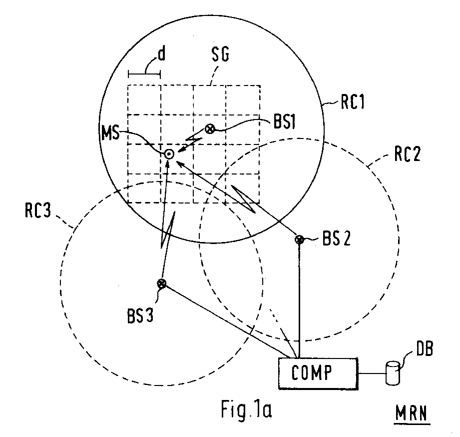
- FIG. 1a schematically shows the structure of a cellular mobile radio network MRN, which contains several radio cells RC1 to RC3, each of Base stations BS1 to BS3 are supplied.
- the base stations are with an evaluation device COMP described later connected, which in turn is connected to a database DB.
- COMP evaluation device
- the Radio cell RC1 which is usually about 15 to 30 km in diameter, in divided small grid squares, which are only an area of 20 m x 20 m cover.
- the group of grid squares SG is only through in Fig. 1 Semicolons indicated and covers here as an example for the entire radio cell RC1 only a part of.
- Fig. 1b it is shown that the group of Segments SG consists of the following segments: A1 to A4, B1 to B4, C1 to C4 and D1 to D4.
- the segments are square Form squares are also called grid squares A1 to D4.
- There are other shapes are also conceivable, such as the honeycomb shape.
- the Grid square C2 like each grid square, is assigned a target data set, which contains at least two setpoints stored in the database DB are.
- the setpoints are determined here by means of a computer, the one Program for radio network planning contains.
- Such computers are Known in the art as so-called "radio network planning tools".
- the programs used calculate the radio propagation predefined models, such as the well-known model from Walfish and Ikegami.
- the setpoints give for the room coordinates of the Grid squares the radio propagation conditions on radio links at least two of the base stations, e.g. the target reception level. Out
- the spatial distances of the grid square can be added to the target values derived from the at least two base stations.
- the database DB contains the following data for each of the grid squares stored: a target data set DS, the at least two setpoints RL1 to RL4 contains, and a counter reading CNT of the traffic in indicates this grid square.
- This example uses as setpoints Reception level stored in the considered grid square should be received. Namely the reception level RL1, that of Radio signals of the base station BS1 is generated, the reception level RL2, which is generated by radio signals from the base station BS2 etc.
- the reception levels are determined by the Attenuation on the radio links is reduced, so that every reception level a measure of the actual spatial distance between the Grid square C2 and the respective radio base station. By the Each set square is therefore uniquely determined for the target data record DS.
- each mobile station including the mobile station shown in FIG. 1a MS is determined using the method described later in which segment (grid square) the mobile station is currently located. If the procedure has been carried out for a large number of mobile stations, a statistic can be created which indicates which segments are the highest Have density of mobile stations.
- An actual data record DS ' is first formed, which is schematic in FIG. 2b is shown.
- the measured values correspond to the reception levels of those radio signals that the mobile station MS currently on the receives different radio links.
- This receive level M1 to M4 are measured by the mobile station MS and sent to the transmit current base station BS1 (serving base station).
- the Measured values are then sent to a base station controller, not shown as part of a common signaling protocol (e.g. MAP protocol the Abis interface in the GSM standard).
- a not shown Protocol analyzer uses the measured values to form input data for one evaluation device COMP. connected to the radio network.
- the input data with the measured values M1 to M4 form the actual data records shown in FIG. 2b DS ', which also contains a map ID in which the identifier of the Mobile station is registered.
- the Evaluation device COMP see Fig. 1a
- FIG. 3 is a block diagram for a method 100 for determining the spatial distribution of traffic within the in Fig. 1a Radio cell RC1 shown is shown as an example.
- the procedure is now as an example for all mobile stations based on the evaluation of the actual data set DS 'described, which is assigned to the mobile station MS.
- a target data record DS is formed.
- the target data record contains at least two target values RL1 to RLn (n ⁇ 2) were calculated using the radio network planning tool and from which the distances between the mobile station MS and the base stations derive.
- an actual data record DS 'is formed as shown in FIG. 2b.
- measured values are first sent individually from the mobile station to the To transmit radio network and then the actual data record DS 'within of the protocol analyzer connected to the evaluation device COMP (not shown) formed. It is also conceivable that the actual data record formed by the mobile station and then to the radio network is transmitted.
- this actual data record DS is now included all target data records DS compared. It should be determined which one the target data records best matches the actual data record, i.e. which of the target data sets correlates most strongly with the actual data set.
- Each data record forms a multi-digit number group.
- the Tuppel initially only comprise two numerical values, i.e. the actual data record DS 'contains the measured values M1 and M2 and the target data records DS contain the setpoints RL1 and RL2.
- a target-actual comparison is used to determine how large the actual values deviate from the nominal values.
- Steps 120 to 160 are for each mobile station within the Radio cell RC1 repeated.
- each of the segments A1 to D4 has one certain meter reading with CNT.
- the counter readings CNT therefore give the spatial distribution of traffic within the radio cell RC1 again.
- As a location for the establishment of a new base station within the radio cell selected the segment that has the highest count and thus the has the highest traffic load.
- segment B1 with CNT 9 particularly suitable for choosing the location of a new one Base station.
- the Reception levels depend on the radio field attenuation on the radio links between the mobile station and the base stations, i.e. the Reception levels are a measure of the distance between the mobile station and the base stations. You can use this reception level Room coordinates can be calculated. It can thus be determined in which of the segments is a mobile station. It is also conceivable instead of reception levels, signal propagation times on the radio links evaluate and compare with each other. It is particularly advantageous both an evaluation of reception levels and an evaluation of signal transit times to perform a particularly reliable calculation to achieve the spatial distribution of traffic. The Calculating traffic can also improve this that the number of measured values and Setpoints is increased, i.e. not just two, but several values are compared with each other. For this purpose, the counter n is iteratively increased by 1 (see step 121 in FIG. 3).
- the measured values from the respective mobile station can be determined and sent to the evaluation device COMP are transmitted. It is also conceivable to compare the measured values on the side of the Mobile network, i.e. by measuring reception levels or signal propagation times in the base stations.
- the radio cell examined in the exemplary embodiment was in divided square segments (grid squares). This measure has the advantage that this division of the radio cell into an existing one Radio network planning tool uses a radio cell in grid squares with a size of 20 x 20 m.
- the data for this Grid squares can be adopted by the radio network planning tool and stored in the database. It is also conceivable for others Select segments to split the radio cell, for example honeycomb segments.
- the size of the segments here became 20 x 20 m selected.
- the evaluation device is a so-called workstation, which is connected to the base stations via a not shown Radio base station control to which a protocol analyzer is connected.
- the use of a protocol analyzer has the advantage that the Measured values are provided in the form of an actual data set, the unchanged for the evaluation and comparison with the target data records is usable.
- the evaluation device can instead of using it directly the protocol analyzer and the radio base station controller are connected, also via a remote data connection (e.g. via ISDN) with the Radio base station control or with a mobile switching center of the Radio network can be connected. Accordingly, the evaluation device not necessarily be part of the mobile network.
- the description of the exemplary embodiment is based on almost ideal ones Radio transmission conditions, i.e. from for the most part existing visual radio connections between the mobile stations and the base stations.
- Radio transmission conditions i.e. from for the most part existing visual radio connections between the mobile stations and the base stations.
- a line of sight radio connection e.g. radio shadowing through buildings
- the measured values in these cases can be so-called "attenuation offset" are corrected.
- This offset can be determine that first runtime measurements are carried out from which the segment is calculated in which the Mobile station should stop. Then the from the Mobile station determined reception level with target reception levels compared, which should be measured within this segment.
- the offset can and can be determined by comparing the actual and target values can be used for later calculations.
- the presented calculation method used by new locations where new radio base stations are used Relief of the existing radio base stations can be set up should. Relief is also possible by setting up so-called Repeaters or from remote antennas possible.
Landscapes
- Engineering & Computer Science (AREA)
- Signal Processing (AREA)
- Computer Networks & Wireless Communication (AREA)
- Physics & Mathematics (AREA)
- Electromagnetism (AREA)
- Mobile Radio Communication Systems (AREA)
Abstract
Description
Funkausbreitungsbedingungen auf Funkstrecken zu mindestens zwei der Funkfeststationen angeben und aus denen die räumlichen Entfernungen des Segmentes zu den mindestens zwei Funkfeststationen ableitbar sind. Danach werden für jede Mobilstation innerhalb der Funkzelle mindestens zwei Meßwerte ermittelt, die von den Längen der Funkstrecken zwischen der Mobilstation und den mindestens zwei Funkfeststationen abhängen. Anschließend wird aus den Meßwerten ein Ist-Datensatz gebildet und mit den Soll-Datensätzen verglichen und es wird dasjenige Segment angegeben, dessen Soll-Datensatz am besten mit dem Ist-Datensatz übereinstimmt. Für das angegebene Segment wird dann ein Zählerstand erhöht, der das Verkehrsaufkommen in diesem Segment angibt.
- Fig. 1
- die schematisch den Aufbau eines Mobilfunknetzes und einen Ausschnitt daraus darstellt;
- Fig. 2
- in der schematisch der Inhalt von Solldatensätzen, die mit einem Ist-Datensatz verglichen werden, dargestellt ist;
- Fig. 3
- die ein Blockschaltbild eines Verfahrens zur Ermittlung der räumlichen Verteilung darstellt.
Claims (10)
- Verfahren (100) zum Ermitteln der räumlichen Verteilung des Verkehrsaufkommens innerhalb einer Funkzelle (RC1) eines zellularen Mobilfunknetzes (MRN) mit Funkfeststation (BS1, BS2, BS3), die jeweils eine der Funkzellen (RC1, RC2, RC3) versorgen, mit folgenden Schritten:die Funkzelle (RC1) wird in mehrere Segmente (A1, A2, A3, ... B1, B2, ...) aufgeteilt, wobei jedem Segment (C2) ein Soll-Datensatz (DS) zugeordnet wird, der mindestens zwei Sollwerte (RL1, RL2) enthält, die für die Raumkoordinaten des Segments (C2) Funkausbreitungsbedingungen auf Funkstrecken zu mindestens zwei der Funkfeststationen (BS1, BS2) angeben und aus denen die räumlichen Entfernungen des Segmentes (C2) zu den mindestens zwei Funkfeststationen (BS1, BS2) ableitbar sind (Schritt 110);für jede Mobilstation (MS) innerhalb der Funkzelle (RC1) werden mindestens zwei Meßwerte (M1, M2) ermittelt, die von den Längen der Funkstrecken zwischen der Mobilstation (MS) und den mindestens zwei Funkfeststationen (BS1, BS2) abhängen (Schritt 130);aus den Meßwerten (M1, M2) wird ein Ist-Datensatz (DS') gebildet und mit den Soll-Datensätzen (DS), die jeweils genau einem der Segmente (A1, A2, A3, ...B1, B2, ...) zugeordnet sind, verglichen (Schritt 140);dasjenige Segment (C2) wird angegeben, dessen Soll-Datensatz (DS) am besten mit dem Ist-Datensatz (DS') übereinstimmt (Schritt 150);für das angegebene Segment (C2) wird ein Zählerstand (CNT), der das Verkehrsaufkommen in diesem Segment angibt, erhöht (Schritt 160).
- Verfahren nach Anspruch 1, bei dem nach Ablauf einer vorgebbaren Zeitspanne die Zählerstände (CNT) für die Segmente (A1, A2, A3, ... B1, B2, ...) miteinander verglichen werden, und daß dasjenige Segment (B1) mit dem höchsten Zählerstand (CNT) angegeben wird als Standort für eine dem Mobilfunknetz (MRN) zusätzlich hinzuzufügende Funkfeststation.
- Verfahren nach Anspruch 1, bei dem die Meßwerte aus Empfangspegeln (M1, M2) ermittelt werden, die durch die Dämpfung auf den Funkstrecken gemindert werden(Schritt 130).
- Verfahren nach Anspruch 1, bei dem die Meßwerte aus Laufzeiten von Funksignalen ermittelt werden, die auf den Funkstrecken übertragen werden.
- Verfahren nach Anspruch 1, bei dem die Meßwerte (M1, M2) von einer jeden Mobilstation (MS) beim Empfang von den Funksignalen, die die Funkfeststationen (BS1, BS2) senden, ermittelt werden und anschließend an diejenige Funkfeststation (BS1) gesendet werden, die die Funkzelle (RC1) versorgt, und daß aus den Meßwerten (M1, M2) Eingangsdaten für eine mit der Funkfeststation (BS1) verbundene Auswerteeinrichtung (COMP) gebildet werden (Schritt 130).
- Verfahren nach Anspruch 5, bei dem die aus den Meßwerten (M1, M2) gebildeten Eingangsdaten in der Auswerteeinrichtung (COMP) zu dem Ist-Datensatz (DS') zusammengefaßt werden, und bei dem dieser Ist-Datensatz (DS') in der Auswerteeinrichtung (COMP), die auf eine Datenbank (DB) zugreift, mit den Soll-Datensätzen (DS) verglichen wird, deren Sollwerte (RL1, RL2) in der Datenbank (DB) gespeichert sind.
- Auswerteeinrichtung (COMP) zum Ermitteln der räumlichen Verteilung des Verkehrsaufkommens innerhalb einer Funkzelle (RC1) eines zellularen Mobilfunknetzes (MRN), bei dem die Funkzelle (RC1) in mehrere Segmente (A1, A2, A3, ... B1, B2, ...) aufgeteilt ist, bei dem die Auswerteeinrichtung (COMP) mit Funkfeststation (BS1, BS2, BS3), die jeweils eine der Funkzellen (RC1, RC2, RC3) versorgen, verbunden ist, bei dem die Auswerteeinrichtung (COMP) mit einer Datenbank (DB) verbunden ist, in der Soll-Datensätze (DS) gespeichert sind, von denen jeder genau einem der Segmente (C2) zugeordnet ist und mindestens zwei Sollwerte (RL1, RL2) enthält, die für die Raumkoordinaten des Segments (C2) Funkausbreitungsbedingungen auf Funkstrecken zu mindestens zwei der Funkfeststationen (BS1, BS2) angeben und aus denen die räumlichen Entfernungen des Segmentes (C2) zu den mindestens zwei Funkfeststationen (BS1, BS2) ableitbar sind, bei dem die Auswerteeinrichtung (COMP) für jede Mobilstation (MS) innerhalb der Funkzelle (RC1) aus mindestens zwei Meßwerten (M1, M2), die von den Längen der Funkstrecken zwischen der Mobilstation (MS) und den mindestens zwei Funkfeststationen (BS1, BS2) abhängen, einen Ist-Datensatz (DS') bildet und mit den Soll-Datensätzen (DS) vergleicht, und bei dem die Auswerteeinrichtung (COMP) dasjenige Segment (C2) angibt, dessen Soll-Datensatz (DS) am besten mit dem Ist-Datensatz (DS') übereinstimmt und für dieses Segment (C2) einen Zählerstand (CNT), der das Verkehrsaufkommen in diesem Segment angibt, erhöht.
- Auswerteeinrichtung (COMP) nach Anspruch 7, die nach Ablauf einer vorgebbaren Zeitspanne die Zählerstände (CNT) für die Segmente (A1, A2, A3, ... B1, B2, ...) miteinander vergleicht, und die dasjenige Segment (B1) mit dem höchsten Zählerstand (CNT) angibt als einen Standort für eine dem Mobilfunknetz (MRN) zusätzlich hinzuzufügende Funkfeststation.
- Mobilfunknetz (MRN) mit einer Auswerteeinrichtung (COMP) zum Ermitteln der räumlichen Verteilung des Verkehrsaufkommens innerhalb einer Funkzelle (RC1) des zellularen Mobilfunknetzes (MRN), bei dem die Funkzelle (RC1) in mehrere Segmente (A1, A2, A3, ... B1, B2, ...) aufgeteilt ist, bei dem die Auswerteeinrichtung (COMP) mit Funkfeststation (BS1, BS2, BS3), die jeweils eine der Funkzellen (RC1, RC2, RC3) versorgen, verbunden ist, bei dem die Auswerteeinrichtung (COMP) mit einer Datenbank (DB) verbunden ist, in der Soll-Datensätze (DS) gespeichert sind, von denen jeder genau einem der Segmente (C2) zugeordnet ist und mindestens zwei Sollwerte (RL1, RL2) enthält, die für die Raumkoordinaten des Segments (C2) Funkausbreitungsbedingungen auf Funkstrecken zu mindestens zwei der Funkfeststationen (BS1, BS2) angeben und aus denen die räumlichen Entfernungen des Segmentes (C2) zu den mindestens zwei Funkfeststationen (BS1, BS2) ableitbar sind, bei dem die Auswerteeinrichtung (COMP) für jede Mobilstation (MS) innerhalb der Funkzelle (RC1) aus mindestens zwei Meßwerten (M1, M2), die von den Längen der Funkstrecken zwischen der Mobilstation (MS) und den mindestens zwei Funkfeststationen (BS1, BS2) abhängen, einen Ist-Datensatz (DS') bildet und mit den Soll-Datensätzen (DS) vergleicht, und bei dem die Auswerteeinrichtung (COMP) dasjenige Segment (C2) angibt, dessen Soll-Datensatz (DS) am besten mit dem Ist-Datensatz (DS') übereinstimmt und für dieses Segment (C2) einen Zählerstand (CNT), der das Verkehrsaufkommen in diesem Segment angibt, erhöht.
- Mobilfunknetz (MRN) nach Anspruch 9, bei dem die Auswerteeinrichtung (COMP) nach Ablauf einer vorgebbaren Zeitspanne die Zählerstände (CNT) für die Segmente (A1, A2, A3, ... B1, B2, ...) miteinander vergleicht und dasjenige Segment (B1) mit dem höchsten Zählerstand (CNT) angibt als einen Standort für eine dem Mobilfunknetz (MRN) zusätzlich hinzuzufügende Funkfeststation.
Applications Claiming Priority (2)
| Application Number | Priority Date | Filing Date | Title |
|---|---|---|---|
| DE19705903 | 1997-02-14 | ||
| DE19705903A DE19705903A1 (de) | 1997-02-14 | 1997-02-14 | Verfahren zum Ermitteln der räumlichen Verteilung der Verkehrsaufkommens in einem Mobilfunknetz |
Publications (2)
| Publication Number | Publication Date |
|---|---|
| EP0861010A2 true EP0861010A2 (de) | 1998-08-26 |
| EP0861010A3 EP0861010A3 (de) | 1999-07-14 |
Family
ID=7820402
Family Applications (1)
| Application Number | Title | Priority Date | Filing Date |
|---|---|---|---|
| EP98440017A Withdrawn EP0861010A3 (de) | 1997-02-14 | 1998-02-06 | Verfahren zum Ermitteln der räumlichen Verteilung des Verkehrsaufkommens in einem Mobilfunknetz |
Country Status (5)
| Country | Link |
|---|---|
| US (1) | US6085095A (de) |
| EP (1) | EP0861010A3 (de) |
| AU (1) | AU735812B2 (de) |
| CA (1) | CA2226539A1 (de) |
| DE (1) | DE19705903A1 (de) |
Cited By (2)
| Publication number | Priority date | Publication date | Assignee | Title |
|---|---|---|---|---|
| EP0868101A3 (de) * | 1997-03-25 | 1999-09-15 | DeTeMobil Deutsche Telekom MobilNet GmbH | Verfahren zur Analyse der Verkehrsdichte in einem Mobilfunknetz |
| EP1115262A1 (de) * | 1999-12-21 | 2001-07-11 | Lucent Technologies Inc. | Lokalisierung von Verkehr in einem mobilen zellularen Telekommunikationssystem |
Families Citing this family (18)
| Publication number | Priority date | Publication date | Assignee | Title |
|---|---|---|---|---|
| DE19920587C2 (de) * | 1999-05-04 | 2001-11-08 | Bernhard Walke | Kombination von Meßwerten von Mobilstationen zur Erstellung und Aktualisierung der Funkfelddatenbank bei drahtlosen und mobilen Funknetzen |
| US6922700B1 (en) * | 2000-05-16 | 2005-07-26 | International Business Machines Corporation | System and method for similarity indexing and searching in high dimensional space |
| US7085592B1 (en) * | 2000-09-29 | 2006-08-01 | Alcatel Canada Inc. | Wireless transmission evaluation system and method |
| EP1204283A1 (de) * | 2000-11-06 | 2002-05-08 | Telefonaktiebolaget L M Ericsson (Publ) | Zellulares Funknetz mit Wiedergebrauch von Frequenzen |
| GB2370193B (en) * | 2000-12-15 | 2004-07-21 | Motorola Inc | Intelligent optimisation system and method of optimising communication performance in a cellular telecommunications network |
| FI110550B (fi) * | 2001-10-10 | 2003-02-14 | Elisa Comm Oyj | Liikkuvan päätelaitteen paikannus |
| DE10251993B4 (de) * | 2002-11-06 | 2012-09-27 | Actix Gmbh | Verfahren und Vorrichtung zur Optimierung von zellularen drahtlosen Nachrichtennetzen |
| KR100560389B1 (ko) * | 2004-07-05 | 2006-03-13 | 한국전자통신연구원 | 무선망 기지국 설계 방법 |
| JP4788905B2 (ja) * | 2006-05-01 | 2011-10-05 | 日本電気株式会社 | 移動通信システム及び基地局アンテナ近接状況判断方法 |
| US9351171B2 (en) | 2006-09-26 | 2016-05-24 | Polaris Wireless, Inc. | Efficient deployment of mobile test units to gather location-dependent radio-frequency data |
| US20080077516A1 (en) * | 2006-09-26 | 2008-03-27 | Polaris Wireless, Inc. | Efficient Deployment of Mobile Test Units to Gather Location-Dependent Radio-Frequency Data |
| US8175607B2 (en) * | 2006-12-18 | 2012-05-08 | Telefonaktiebolaget Lm Ericsson (Publ) | Network configuration audit |
| US7813301B2 (en) * | 2008-05-08 | 2010-10-12 | Verizon Patent And Licensing Inc. | Shrink wrap technique for enclosing multiple polygons |
| CN102413480B (zh) * | 2010-09-21 | 2014-04-30 | 中兴通讯股份有限公司 | 反向测试覆盖的方法及系统 |
| US9705649B2 (en) * | 2013-08-12 | 2017-07-11 | Telefonaktiebolaget L M Ericsson (Publ) | Mobile relay node based CoMP assisted interference mitigation |
| JP6341831B2 (ja) * | 2014-10-16 | 2018-06-13 | Kddi株式会社 | エリア毎のデータトラヒック量を推定する装置、プログラム及び方法 |
| JP6412078B2 (ja) * | 2016-09-28 | 2018-10-24 | ソフトバンク株式会社 | シミュレーション装置および制御プログラム |
| US10498630B1 (en) * | 2018-07-14 | 2019-12-03 | Microsoft Technology Licensing, Llc | Intelligent device selection for pilot testing |
Family Cites Families (13)
| Publication number | Priority date | Publication date | Assignee | Title |
|---|---|---|---|---|
| US5293645A (en) * | 1991-10-04 | 1994-03-08 | Sharp Microelectronics Technology, Inc. | Apparatus and method for locating mobile and portable radio terminals in a radio network |
| SE469581B (sv) * | 1992-08-18 | 1993-07-26 | Televerket | Foerfarande foer uppskattning av trafikdensitet i mobiltelefonnaet |
| SE9202466L (sv) * | 1992-08-28 | 1993-07-26 | Televerket | Foerfarande och anordning vid mobila telekommunikationsnaet foer att moejliggoera en foerbaettrad cellplanering |
| JPH06268574A (ja) * | 1993-03-11 | 1994-09-22 | Hitachi Ltd | セルラ移動通信システム |
| SE9301695L (sv) * | 1993-05-17 | 1994-09-12 | Ericsson Telefon Ab L M | Förfarande och anordning vid kanalutnyttjandet i ett radiokommunikationssystem |
| NL9301684A (nl) * | 1993-09-30 | 1995-04-18 | Nederland Ptt | Werkwijze voor het bepalen van basisstationlocaties, en inrichting voor toepassing van de werkwijze. |
| US5537460A (en) * | 1994-07-08 | 1996-07-16 | Holliday, Jr.; Robert O. | Method and apparatus for determining the precise location of a modified cellular telephone using registration messages and reverse control channel transmission |
| JPH0823567A (ja) * | 1994-07-11 | 1996-01-23 | Hitachi Ltd | 無線通信システムおよび通話チャネル割当方法 |
| US5475870A (en) * | 1994-09-12 | 1995-12-12 | Qualcomm Incorporated | Apparatus and method for adding and removing a base station from a cellular communications system |
| US5613217A (en) * | 1995-05-03 | 1997-03-18 | Telefonaktiebolaget Lm Ericsson | Transceiver site selection a cellular communications system |
| US5657487A (en) * | 1995-06-05 | 1997-08-12 | Airnet Communications Corporation | Mobile telephone location process making use of handoff data |
| US5828926A (en) * | 1995-08-17 | 1998-10-27 | Ricoh Company, Ltd. | Registration control for an image forming apparatus having an intermediate transfer belt |
| FR2747874B1 (fr) * | 1996-04-18 | 1998-07-03 | France Telecom | Procede d'analyse de la localisation trafic dans un reseau de radiocommunication cellulaire |
-
1997
- 1997-02-14 DE DE19705903A patent/DE19705903A1/de not_active Withdrawn
-
1998
- 1998-02-06 EP EP98440017A patent/EP0861010A3/de not_active Withdrawn
- 1998-02-11 AU AU53889/98A patent/AU735812B2/en not_active Ceased
- 1998-02-12 US US09/023,409 patent/US6085095A/en not_active Expired - Fee Related
- 1998-02-13 CA CA002226539A patent/CA2226539A1/en not_active Abandoned
Cited By (2)
| Publication number | Priority date | Publication date | Assignee | Title |
|---|---|---|---|---|
| EP0868101A3 (de) * | 1997-03-25 | 1999-09-15 | DeTeMobil Deutsche Telekom MobilNet GmbH | Verfahren zur Analyse der Verkehrsdichte in einem Mobilfunknetz |
| EP1115262A1 (de) * | 1999-12-21 | 2001-07-11 | Lucent Technologies Inc. | Lokalisierung von Verkehr in einem mobilen zellularen Telekommunikationssystem |
Also Published As
| Publication number | Publication date |
|---|---|
| CA2226539A1 (en) | 1998-08-14 |
| DE19705903A1 (de) | 1998-08-20 |
| AU735812B2 (en) | 2001-07-19 |
| EP0861010A3 (de) | 1999-07-14 |
| US6085095A (en) | 2000-07-04 |
| AU5388998A (en) | 1998-08-20 |
Similar Documents
| Publication | Publication Date | Title |
|---|---|---|
| EP0861010A2 (de) | Verfahren zum Ermitteln der räumlichen Verteilung des Verkehrsaufkommens in einem Mobilfunknetz | |
| DE69321183T2 (de) | Automatisches Leistungsregelungssystem für Mobilfunksysteme | |
| DE69834260T2 (de) | Verfahren und anordnung zur wiederholer verwaltung | |
| DE60011194T2 (de) | Verfahren zur Bestimmung des drahtloses Versorgungsbereichs | |
| DE69629887T2 (de) | Verfahren zur Aufstellung von Steuerungskanälen in einem Zellular mobilen Kommunikationssystem | |
| DE69526420T2 (de) | Verfahren zur Detektion des Interferenzstands einer Basisstation eines mobilen Funkübertragungssystems | |
| DE69714635T2 (de) | Leistungsregelung in einer zellularen Kommunikationsanordnung | |
| DE60038399T2 (de) | Nachrichtenverteilungsverfahren und Nachrichteninformationsverteilungs-Steuerinformations-Einrichtung | |
| DE69108793T2 (de) | Verfahren zur Regelung der Leistung in einem digitalen Mobilfunkkomunikationssystem. | |
| DE69900275T2 (de) | Weiterreichsteuerung in einem CDMA Zellularsystem | |
| DE69109552T2 (de) | Verfahren zum Weiterreichen in einem Zellularmobilkommunikationssystem. | |
| DE69325988T2 (de) | Verfahren zur schätzung der dichte der c/i (trägerstrom/interferenz) und der interferenzprobabilität im aufweg | |
| EP0843422A2 (de) | Verfahren und Anordnung zum Verbessern der Übertragungsqualität in einem Punkt-zu-Mehrpunkt Funkübertragungssystem | |
| WO2020099032A1 (de) | Ladesystem für elektrofahrzeuge | |
| DE102017205479B4 (de) | Verfahren zur Vorhersage einer Mobilfunksignalstärke einer Mobilfunkanbindung eines Kraftfahrzeugs und Servervorrichtung zum Ausführen des Verfahrens | |
| DE102009049672A1 (de) | Konzept zum Generieren von Erfahrungsmeldungen zur Aktualisierung einer Referenzdatenbank | |
| DE102015011271A1 (de) | Vorrichtung und Verfahren zum Organisieren eines Fahrzeugkonvois und Fahrzeug mit dieser Vorrichtung | |
| DE112010003869T5 (de) | Verfahren und System zum Ermitteln der Position von einer sich bewegendendrahtlosen Kommunikationseinheit | |
| WO2007025870A1 (de) | Verfahren und anordnung zur ortung eines mobilen endgerätes in einer mehrzellen-funkanordnung | |
| DE69533351T2 (de) | Verfahren zur automatischen Bildung einer peripheren Zoneninformation | |
| DE69831481T2 (de) | Verfahren zur Störpegelsschätzung in einem Funksystem | |
| DE19507866C2 (de) | Mobilfunkübertragungssystem mit integrierter Meßeinrichtung zum Ausmessen des Funkversorgungsbereichs | |
| DE69830563T2 (de) | Topologie Untersuchungsverfahren und Änderungsverfahren für zellulares Kommunikationssystem | |
| EP0849966A2 (de) | Testsender, Verfahren und Rechner zum Testen eines zellularen Mobilfunknetzes | |
| EP1111950A2 (de) | Mobilfunkgerät eines zellularen Netzwerkes zum Übertragen von Sprache und/oder Daten und Verfahren für ein solches |
Legal Events
| Date | Code | Title | Description |
|---|---|---|---|
| PUAI | Public reference made under article 153(3) epc to a published international application that has entered the european phase |
Free format text: ORIGINAL CODE: 0009012 |
|
| AK | Designated contracting states |
Kind code of ref document: A2 Designated state(s): DE ES FI FR GB IT SE |
|
| AX | Request for extension of the european patent |
Free format text: AL;LT;LV;MK;RO;SI |
|
| RAP3 | Party data changed (applicant data changed or rights of an application transferred) |
Owner name: ALCATEL |
|
| RAP3 | Party data changed (applicant data changed or rights of an application transferred) |
Owner name: ALCATEL |
|
| PUAL | Search report despatched |
Free format text: ORIGINAL CODE: 0009013 |
|
| AK | Designated contracting states |
Kind code of ref document: A3 Designated state(s): AT BE CH DE DK ES FI FR GB GR IE IT LI LU MC NL PT SE |
|
| AX | Request for extension of the european patent |
Free format text: AL;LT;LV;MK;RO;SI |
|
| 17P | Request for examination filed |
Effective date: 19991026 |
|
| AKX | Designation fees paid |
Free format text: DE ES FI FR GB IT SE |
|
| STAA | Information on the status of an ep patent application or granted ep patent |
Free format text: STATUS: THE APPLICATION IS DEEMED TO BE WITHDRAWN |
|
| 18D | Application deemed to be withdrawn |
Effective date: 20050901 |