EP0861460B1 - Vorrichtung und verfahren zur einstellung von ionenkonzentrationen - Google Patents
Vorrichtung und verfahren zur einstellung von ionenkonzentrationen Download PDFInfo
- Publication number
- EP0861460B1 EP0861460B1 EP96938065A EP96938065A EP0861460B1 EP 0861460 B1 EP0861460 B1 EP 0861460B1 EP 96938065 A EP96938065 A EP 96938065A EP 96938065 A EP96938065 A EP 96938065A EP 0861460 B1 EP0861460 B1 EP 0861460B1
- Authority
- EP
- European Patent Office
- Prior art keywords
- electrolyte
- solution
- ion
- adjustment
- diffusion
- Prior art date
- Legal status (The legal status is an assumption and is not a legal conclusion. Google has not performed a legal analysis and makes no representation as to the accuracy of the status listed.)
- Expired - Lifetime
Links
- 238000000034 method Methods 0.000 title claims description 37
- 230000008569 process Effects 0.000 title claims description 13
- 239000003792 electrolyte Substances 0.000 claims description 120
- 150000002500 ions Chemical class 0.000 claims description 74
- 230000007935 neutral effect Effects 0.000 claims description 49
- 238000009792 diffusion process Methods 0.000 claims description 41
- 239000002253 acid Substances 0.000 claims description 35
- 150000001768 cations Chemical class 0.000 claims description 24
- 150000001450 anions Chemical class 0.000 claims description 23
- 239000012528 membrane Substances 0.000 claims description 21
- 230000008859 change Effects 0.000 claims description 17
- 239000000203 mixture Substances 0.000 claims description 15
- 230000008929 regeneration Effects 0.000 claims description 10
- 238000011069 regeneration method Methods 0.000 claims description 10
- 238000011049 filling Methods 0.000 claims description 9
- 238000002156 mixing Methods 0.000 claims description 9
- 230000036961 partial effect Effects 0.000 claims description 9
- 239000000499 gel Substances 0.000 claims description 6
- 239000000126 substance Substances 0.000 claims description 6
- 238000004448 titration Methods 0.000 claims description 6
- 238000012546 transfer Methods 0.000 claims description 6
- 238000006243 chemical reaction Methods 0.000 claims description 5
- 239000007789 gas Substances 0.000 claims description 4
- 238000000954 titration curve Methods 0.000 claims description 4
- 238000010276 construction Methods 0.000 claims description 3
- 238000006467 substitution reaction Methods 0.000 claims description 3
- 239000007784 solid electrolyte Substances 0.000 claims description 2
- 238000009423 ventilation Methods 0.000 claims description 2
- 230000000994 depressogenic effect Effects 0.000 claims 9
- GPRLSGONYQIRFK-UHFFFAOYSA-N hydron Chemical compound [H+] GPRLSGONYQIRFK-UHFFFAOYSA-N 0.000 claims 2
- 239000011148 porous material Substances 0.000 claims 2
- 238000005842 biochemical reaction Methods 0.000 claims 1
- QXJJQWWVWRCVQT-UHFFFAOYSA-K calcium;sodium;phosphate Chemical compound [Na+].[Ca+2].[O-]P([O-])([O-])=O QXJJQWWVWRCVQT-UHFFFAOYSA-K 0.000 claims 1
- 230000000881 depressing effect Effects 0.000 claims 1
- 238000001514 detection method Methods 0.000 claims 1
- 239000000835 fiber Substances 0.000 claims 1
- 230000000087 stabilizing effect Effects 0.000 claims 1
- 239000000243 solution Substances 0.000 description 132
- HEMHJVSKTPXQMS-UHFFFAOYSA-M Sodium hydroxide Chemical compound [OH-].[Na+] HEMHJVSKTPXQMS-UHFFFAOYSA-M 0.000 description 15
- 230000033228 biological regulation Effects 0.000 description 13
- 239000000872 buffer Substances 0.000 description 12
- 238000010979 pH adjustment Methods 0.000 description 12
- 230000006870 function Effects 0.000 description 10
- 230000002378 acidificating effect Effects 0.000 description 9
- 239000003638 chemical reducing agent Substances 0.000 description 9
- -1 of NaNO 3 ) Chemical class 0.000 description 9
- 239000008151 electrolyte solution Substances 0.000 description 8
- 229940021013 electrolyte solution Drugs 0.000 description 8
- 230000001105 regulatory effect Effects 0.000 description 8
- FAPWRFPIFSIZLT-UHFFFAOYSA-M Sodium chloride Chemical compound [Na+].[Cl-] FAPWRFPIFSIZLT-UHFFFAOYSA-M 0.000 description 6
- 238000000502 dialysis Methods 0.000 description 6
- BASFCYQUMIYNBI-UHFFFAOYSA-N platinum Chemical compound [Pt] BASFCYQUMIYNBI-UHFFFAOYSA-N 0.000 description 6
- 230000004044 response Effects 0.000 description 6
- XLYOFNOQVPJJNP-UHFFFAOYSA-N water Substances O XLYOFNOQVPJJNP-UHFFFAOYSA-N 0.000 description 6
- 230000004888 barrier function Effects 0.000 description 5
- 238000013461 design Methods 0.000 description 5
- 239000003014 ion exchange membrane Substances 0.000 description 5
- 239000007788 liquid Substances 0.000 description 5
- 238000005259 measurement Methods 0.000 description 5
- 239000000047 product Substances 0.000 description 5
- 238000006479 redox reaction Methods 0.000 description 5
- 230000009467 reduction Effects 0.000 description 5
- 238000000926 separation method Methods 0.000 description 5
- 230000032258 transport Effects 0.000 description 5
- 230000015572 biosynthetic process Effects 0.000 description 4
- 239000008366 buffered solution Substances 0.000 description 4
- 230000001419 dependent effect Effects 0.000 description 4
- FGIUAXJPYTZDNR-UHFFFAOYSA-N potassium nitrate Chemical compound [K+].[O-][N+]([O-])=O FGIUAXJPYTZDNR-UHFFFAOYSA-N 0.000 description 4
- 230000002829 reductive effect Effects 0.000 description 4
- 150000003839 salts Chemical class 0.000 description 4
- 239000012047 saturated solution Substances 0.000 description 4
- 238000003860 storage Methods 0.000 description 4
- VEXZGXHMUGYJMC-UHFFFAOYSA-N Hydrochloric acid Chemical compound Cl VEXZGXHMUGYJMC-UHFFFAOYSA-N 0.000 description 3
- 150000007513 acids Chemical class 0.000 description 3
- 239000003011 anion exchange membrane Substances 0.000 description 3
- 230000008901 benefit Effects 0.000 description 3
- 239000003795 chemical substances by application Substances 0.000 description 3
- 230000007423 decrease Effects 0.000 description 3
- 238000005868 electrolysis reaction Methods 0.000 description 3
- 238000005516 engineering process Methods 0.000 description 3
- 239000011521 glass Substances 0.000 description 3
- XLYOFNOQVPJJNP-UHFFFAOYSA-M hydroxide Chemical compound [OH-] XLYOFNOQVPJJNP-UHFFFAOYSA-M 0.000 description 3
- WQYVRQLZKVEZGA-UHFFFAOYSA-N hypochlorite Chemical compound Cl[O-] WQYVRQLZKVEZGA-UHFFFAOYSA-N 0.000 description 3
- 238000007654 immersion Methods 0.000 description 3
- 230000007246 mechanism Effects 0.000 description 3
- 230000020477 pH reduction Effects 0.000 description 3
- 229910052697 platinum Inorganic materials 0.000 description 3
- 239000004065 semiconductor Substances 0.000 description 3
- 239000011780 sodium chloride Substances 0.000 description 3
- OKTJSMMVPCPJKN-UHFFFAOYSA-N Carbon Chemical compound [C] OKTJSMMVPCPJKN-UHFFFAOYSA-N 0.000 description 2
- 101100390736 Danio rerio fign gene Proteins 0.000 description 2
- 102000004190 Enzymes Human genes 0.000 description 2
- 108090000790 Enzymes Proteins 0.000 description 2
- 101100390738 Mus musculus Fign gene Proteins 0.000 description 2
- 239000007983 Tris buffer Substances 0.000 description 2
- 238000009825 accumulation Methods 0.000 description 2
- 239000007864 aqueous solution Substances 0.000 description 2
- 229910052799 carbon Inorganic materials 0.000 description 2
- 238000005341 cation exchange Methods 0.000 description 2
- 239000007795 chemical reaction product Substances 0.000 description 2
- 238000000576 coating method Methods 0.000 description 2
- 238000011109 contamination Methods 0.000 description 2
- 239000013078 crystal Substances 0.000 description 2
- 238000007872 degassing Methods 0.000 description 2
- 238000006073 displacement reaction Methods 0.000 description 2
- 239000012153 distilled water Substances 0.000 description 2
- 230000000694 effects Effects 0.000 description 2
- 238000003411 electrode reaction Methods 0.000 description 2
- 230000005669 field effect Effects 0.000 description 2
- PCHJSUWPFVWCPO-UHFFFAOYSA-N gold Chemical compound [Au] PCHJSUWPFVWCPO-UHFFFAOYSA-N 0.000 description 2
- 239000010931 gold Substances 0.000 description 2
- 229910052737 gold Inorganic materials 0.000 description 2
- 230000002401 inhibitory effect Effects 0.000 description 2
- 238000005342 ion exchange Methods 0.000 description 2
- 230000037427 ion transport Effects 0.000 description 2
- 238000011068 loading method Methods 0.000 description 2
- 230000007774 longterm Effects 0.000 description 2
- 238000004519 manufacturing process Methods 0.000 description 2
- 230000004048 modification Effects 0.000 description 2
- 238000012986 modification Methods 0.000 description 2
- 230000000144 pharmacologic effect Effects 0.000 description 2
- 239000004033 plastic Substances 0.000 description 2
- 229920003023 plastic Polymers 0.000 description 2
- 230000000607 poisoning effect Effects 0.000 description 2
- 230000029219 regulation of pH Effects 0.000 description 2
- 229910001415 sodium ion Inorganic materials 0.000 description 2
- LENZDBCJOHFCAS-UHFFFAOYSA-N tris Chemical compound OCC(N)(CO)CO LENZDBCJOHFCAS-UHFFFAOYSA-N 0.000 description 2
- 229910019142 PO4 Inorganic materials 0.000 description 1
- QAOWNCQODCNURD-UHFFFAOYSA-N Sulfuric acid Chemical compound OS(O)(=O)=O QAOWNCQODCNURD-UHFFFAOYSA-N 0.000 description 1
- 210000001015 abdomen Anatomy 0.000 description 1
- 238000010521 absorption reaction Methods 0.000 description 1
- 230000009471 action Effects 0.000 description 1
- 230000006978 adaptation Effects 0.000 description 1
- 239000000654 additive Substances 0.000 description 1
- 239000000853 adhesive Substances 0.000 description 1
- 230000001070 adhesive effect Effects 0.000 description 1
- 230000002411 adverse Effects 0.000 description 1
- 239000002585 base Substances 0.000 description 1
- 239000011324 bead Substances 0.000 description 1
- 229910001423 beryllium ion Inorganic materials 0.000 description 1
- 238000002306 biochemical method Methods 0.000 description 1
- 238000004061 bleaching Methods 0.000 description 1
- 239000007853 buffer solution Substances 0.000 description 1
- 239000012928 buffer substance Substances 0.000 description 1
- 230000003139 buffering effect Effects 0.000 description 1
- 239000006285 cell suspension Substances 0.000 description 1
- XTEGARKTQYYJKE-UHFFFAOYSA-M chlorate Inorganic materials [O-]Cl(=O)=O XTEGARKTQYYJKE-UHFFFAOYSA-M 0.000 description 1
- 238000004140 cleaning Methods 0.000 description 1
- 239000011248 coating agent Substances 0.000 description 1
- LYKJEJVAXSGWAJ-UHFFFAOYSA-N compactone Natural products CC1(C)CCCC2(C)C1CC(=O)C3(O)CC(C)(CCC23)C=C LYKJEJVAXSGWAJ-UHFFFAOYSA-N 0.000 description 1
- 239000002131 composite material Substances 0.000 description 1
- 230000003750 conditioning effect Effects 0.000 description 1
- 230000001276 controlling effect Effects 0.000 description 1
- 238000012937 correction Methods 0.000 description 1
- 238000002425 crystallisation Methods 0.000 description 1
- 230000008025 crystallization Effects 0.000 description 1
- 230000003247 decreasing effect Effects 0.000 description 1
- 239000000645 desinfectant Substances 0.000 description 1
- 230000006866 deterioration Effects 0.000 description 1
- 238000002405 diagnostic procedure Methods 0.000 description 1
- 238000005553 drilling Methods 0.000 description 1
- 239000003814 drug Substances 0.000 description 1
- 230000005684 electric field Effects 0.000 description 1
- 230000005611 electricity Effects 0.000 description 1
- 238000002848 electrochemical method Methods 0.000 description 1
- 230000005518 electrochemistry Effects 0.000 description 1
- 238000005370 electroosmosis Methods 0.000 description 1
- 230000002255 enzymatic effect Effects 0.000 description 1
- 230000002068 genetic effect Effects 0.000 description 1
- 238000010353 genetic engineering Methods 0.000 description 1
- 230000006872 improvement Effects 0.000 description 1
- 239000003112 inhibitor Substances 0.000 description 1
- 230000002452 interceptive effect Effects 0.000 description 1
- 238000001155 isoelectric focusing Methods 0.000 description 1
- 239000000463 material Substances 0.000 description 1
- 230000005499 meniscus Effects 0.000 description 1
- 210000004088 microvessel Anatomy 0.000 description 1
- 230000001617 migratory effect Effects 0.000 description 1
- 238000003801 milling Methods 0.000 description 1
- 239000003607 modifier Substances 0.000 description 1
- 230000003287 optical effect Effects 0.000 description 1
- 230000003204 osmotic effect Effects 0.000 description 1
- 239000003002 pH adjusting agent Substances 0.000 description 1
- 238000001139 pH measurement Methods 0.000 description 1
- 238000005192 partition Methods 0.000 description 1
- 230000035699 permeability Effects 0.000 description 1
- NBIIXXVUZAFLBC-UHFFFAOYSA-K phosphate Chemical compound [O-]P([O-])([O-])=O NBIIXXVUZAFLBC-UHFFFAOYSA-K 0.000 description 1
- 239000010452 phosphate Substances 0.000 description 1
- 239000008363 phosphate buffer Substances 0.000 description 1
- 239000008055 phosphate buffer solution Substances 0.000 description 1
- 239000002574 poison Substances 0.000 description 1
- 231100000614 poison Toxicity 0.000 description 1
- 239000002243 precursor Substances 0.000 description 1
- 230000003449 preventive effect Effects 0.000 description 1
- 108090000623 proteins and genes Proteins 0.000 description 1
- 102000004169 proteins and genes Human genes 0.000 description 1
- 238000004904 shortening Methods 0.000 description 1
- 239000010703 silicon Substances 0.000 description 1
- 229910052710 silicon Inorganic materials 0.000 description 1
- 239000007787 solid Substances 0.000 description 1
- 241000894007 species Species 0.000 description 1
- 229910001220 stainless steel Inorganic materials 0.000 description 1
- 239000010935 stainless steel Substances 0.000 description 1
- 239000012086 standard solution Substances 0.000 description 1
- 230000001954 sterilising effect Effects 0.000 description 1
- 238000004659 sterilization and disinfection Methods 0.000 description 1
- 230000009182 swimming Effects 0.000 description 1
- 239000008399 tap water Substances 0.000 description 1
- 235000020679 tap water Nutrition 0.000 description 1
- 230000002123 temporal effect Effects 0.000 description 1
- 238000005406 washing Methods 0.000 description 1
Images






Classifications
-
- G—PHYSICS
- G05—CONTROLLING; REGULATING
- G05D—SYSTEMS FOR CONTROLLING OR REGULATING NON-ELECTRIC VARIABLES
- G05D21/00—Control of chemical or physico-chemical variables, e.g. pH value
- G05D21/02—Control of chemical or physico-chemical variables, e.g. pH value characterised by the use of electric means
Definitions
- the invention relates to an apparatus and a method with whose help is the amperometric concentration of ions in a solution can be set, regulated and measured.
- the invention relates in particular to a pH adjustment and control device.
- any pH shift - whether intentional or unwanted, whether on electrodes or in free solution - is based on the fact that the difference between the sum of all cations minus the sum of all anions shifts in the solution under consideration (the H + and OH - -Ions must not be counted).
- a method that affects the pH of a solution by electrical means must therefore be able to change this difference.
- the necessary prerequisites for this result from the classic works by Kohlrausch (Ann. D. Phys., 62 (1897) 209), Logsworth (J. Am. Chem. Soc. 67 (1945) 1109), and MacInnes (The Principles of Electrochemistry, Reinhold Publ. Co., New York 1939) and will be explained using a NaNO 3 solution:
- the Na + concentration In order to make the solution more basic, the Na + concentration must be increased and / or the NO 3 - concentration reduced. If the control is to be carried out electrically, this requires that the number of Na ions introduced into the solution by an electrical route is greater than the number of Na ions emerging at the same time.
- a pH change controlled by redox reactions is only possible in exceptional cases, for example with the system from Shimomura et al. (Shimomura, O., J. Crystal Growth 144, 253, 1994, Shimomura, O., Trans IECE Japan J 67 C, 673, 1984; Yokotani, A., Kolde, H., Sasaki, T., Yamanaka, T. and Yamanaka, C., J. Crystal Growth 67, 627, 1984).
- This system affects the amperometric pH tracking when growing KDP single crystals in saturated Solutions in containers of characteristic dimensions of the order of magnitude 20 to 30 cm over the course of several months and exhibits the following disadvantages.
- the pH adjustment allows for Compensation for pH changes in the saturated solution due to of crystal growth just a one-way pH change.
- the electrolyte is placed in a middle room adjacent anode compartment with the electrolyte one to the Adjoining cathode compartment mixed so that anions, especially with NaCl-containing solutions e.g. B. disruptive Hypochlorite ions, active from the anode compartment through the cathode compartment can get into the setting room (the same applies to the Cations).
- anions especially with NaCl-containing solutions e.g. B. disruptive Hypochlorite ions
- active from the anode compartment through the cathode compartment can get into the setting room (the same applies to the Cations).
- Such mixing is due to many applications the poisoning effect mentioned is not acceptable.
- the pH change is extremely slow.
- DE-OS 1 571 723 discloses a method for pH tracking in electrolysis processes with pH changes in the solution to be electrolyzed.
- One or two electrolyte chambers are provided, with which H + ions and corresponding counterions are introduced into the solution to be adjusted in order to increase the pH.
- the process for introducing OH - ions can be used.
- the method according to DE-OS 1 571 723 has the following limitation. No pH adjustment or control is possible since the pH adjustment is slow and only in one direction (either increasing or decreasing the pH) can.
- the present invention has for its object an improved Device for influencing the ion concentration amperometric basis and a method of operating them create with which the disadvantages of conventional systems are overcome and the shortened response times and the implementation allow from control loops. It is a particular task of the Invention to provide an improved pH adjuster that with pH control properties over wide pH ranges for general Applications e.g. B. in medicine, pharmacology, chemistry and others technological applications can be used.
- the invention is based on the idea of creating a device deviating from the known techniques, at least three Electrically controllable electrolyte areas are provided with which selectively transportable ions into a setting solution are.
- An electrolyte area is a definable volume that contains at least one control electrode and a physical one Phase boundary (diffusion-reducing agent, e.g. membrane, Capillary, diaphragm or the like) with the adjustment solution or a Setting area can be connected.
- the control electrode will depending on the function of the electrolyte area as cathode or anode operated.
- the invention can and cannot be used with any type of ion limited to the adjustment of pH values.
- the setting an ion concentration also includes the possibility of at least one partial substitution of an ion composition.
- the setting is preferably carried out by forming a control loop, can also be used in systems with known properties (Buffer capacity, ion transport, etc.) exclusively via a Control currents are measured.
- acid or base regulator designated.
- the invention contains Device three electrolyte areas, which include: (A) one area that with the adjusting solution essentially anions (especially OH ions) can be exchanged (for pH systems: base regulator), (B) an area that matches the adjustment solution in the can exchange essential cations (especially H ions) (for pH systems: acid regulator), and (C) a range that Exchange any cations and anions with the adjustment solution can (for pH systems: so-called neutral phase).
- the chemical composition the solutions in the areas is their respective Function adapted.
- the electrolytes can be particularly weak salty solutions, distilled water, acids, bases or moistened Include salts.
- the ion concentration or conductivity can be changed by either the acid and base regulators (reduction of the Conductivity) or two neutral phases (increase in conductivity) in each case with one another or with a further electrode the adjustment solution.
- the neutral phase is for operation with current reversal set up.
- the adjustment solution within The setting times can be effectively prevented by an ongoing Exchange of the electrolyte at least in the neutral phase or Means for reducing the ion mobility (e.g. convection-preventing Additives such as gels or the like, highly concentrated Electrolytes or moist salts) are provided in the neutral phase be.
- Means for reducing the ion mobility e.g. convection-preventing Additives such as gels or the like, highly concentrated Electrolytes or moist salts
- the Field strength reduced to a minimum so that the ions only move at a slow speed.
- the device according to the invention comprises avoidance a current reversal and thus a transport of redox products electrodes in the adjustment solution four electrolyte areas, two neutral phases are provided.
- the invention is not based on the realization of three or four Electrolyte areas limited, but with any number Electrolyte areas feasible.
- the Electrolyte areas in pairs or all with provided common holding means means the common bracket in pairs the common bracket an acid or base regulator each with a neutral phase (pH adjustment) or the common bracket of an acid and a base regulator or neutral phases (ion adjustment).
- the holding means can be formed by a carrier on which the electrolyte regions are spaced apart from one another End are attached.
- the holding means can also be a component are formed, into which the electrolyte areas are integrated adjacent to each other.
- the defined relative positioning on the holding means results firstly, simple, common handling (in particular Immersion in the setting solution) of the held Electrolyte areas and secondly any, but constant distance and thus constant current paths between the shared chambers.
- Electrolyte areas in pairs or all be arranged adjacent to each other are adjacent to each other.
- Diffusion reducing agents are adjacent to one another when the lateral edge of an anti-diffusion agent either directly the lateral edge of another diffusion reducing Touches means or is at a distance from it is significantly less (e.g. factor 0.5 or less) than one characteristic size of the setting volume (e.g. vessel diameter).
- Adjustment solution can be mixed or stirred during adjustment.
- the Mixing can be either active by means of an agitator or passive (especially with small volumes) by diffusion. Separate agitators (e.g. magnetic Stirrer) or the pH adjustment device itself.
- Means for reduction can be found in at least one of the electrolyte areas or influencing the ion mobility be.
- diffusion reducing structures especially for Formation of a sequence of agitated, well-mixed and agitated, diffusion-reduced zones
- the use of multiple electrodes Especially with a suitable arrangement e.g. partially insulated far or close in relation to the diaphragm) per Electrolyte area and circulation systems can be provided.
- the invention makes compact, feedback-controllable in particular pH adjustment devices (e.g. in the form of pH electrodes) created or procedures in which jointly held Electrolyte chambers together or in separable sub-groups are provided and the volume is not or by one each determinable displacement in a reproducible way change that (with constant volume) the conductivity of an adjustment range do not change the qualitative composition if necessary keep the solution to be set constant or set it specifically and retain any resulting electrode reaction products, or where the solution to be calibrated in its chemical Composition does not have to be known and in the scheme can be disregarded.
- pH adjustment devices e.g. in the form of pH electrodes
- a method for amperometric adjustment the ion concentration of an adjustment solution comprises the steps Filling a system for amperometric ion concentration adjustment, the at least three chamber-shaped electrolyte areas has, each a control electrode and diffusion reducing Contain agents, with a variety of electrolyte solutions, simultaneous connection of the diffusion reducing agents of the Electrolyte areas with the adjustment solution, and control each Electrolyte area with a separate control current, with Current flow through the control electrodes ions from the electrolyte solutions about the diffusion reducing agents in such a way Adjustment solution that are transported Ion concentration changes.
- Regulation according to the method according to the invention is carried out by a control deviation from the desired ion concentration or pH is measured using one or more sensor means and then compensated by amperometric means.
- the Sensor means can be ion sensors, pH electrodes or measuring means include the actual value indirectly by measuring a Actual value-dependent parameters of the setting solution z. B. via a Capture optical spectroscopic measurement (e.g. absorption).
- the Sensor means preferably have a short response time. pH electrodes on FET basis with response times in the range of 1 s are therefore particularly well suited.
- the ion composition e.g. the pH value
- the conductivity of the Solution is adjustable.
- Any volumes are only by making liquid contact with the diffusion reducing agents Average or partial immersion adjustable.
- the Solution volume is not or only slightly through the setting process changed.
- the system is also a flow system operable.
- Redox processes on the electrodes are caused by adjusting the ion concentration decoupled.
- the setting range is about Phase boundaries connected to the electrolyte areas. Of the Adjustment range thus contains - except possibly sensor electrodes - no electrodes.
- the possibly unknown composition, Solution to be set (setting solution) is through the setting process not consumed or poisoned with redox products. Interfering redox products on the electrodes are generally caused by adequate demarcation and for devices with four and more chamber due to the unchanged polarity during operation the chambers are kept away from the adjustment solution.
- the construction of an easily manageable and electronically controllable, possibly programmable system is possible, in particular can be used in any vessel.
- the system is long-term stable and, at least in its essential parts, reusable and interchangeable if necessary.
- Compatibility with conventional laboratory systems of any geometry (e.g. on so-called. "Eppendorf tubes") or electrical function (e.g. on pH measuring devices, voltmeters or similar) is possible.
- the system can e.g. B. in pen form with subchambers, possibly in combination with one Be regular or extremely miniaturized.
- There are commercially available pH electrode connections or complete Sensor systems (FET electrodes, glass electrodes etc.) for education of a control loop (pH value acquisition) can be used.
- the system is regenerable.
- pH-acid-base adjustment is an analog record of the control procedure possible according to a titration protocol.
- They are fixed pH values adjustable or pH programs, such as pH jumps, pH stairs, Courses with linear, exponential or other temporal Increases and decreases, or iterative courses and Gradients with repeatable characteristics, passable.
- the ion concentration setting is not made via a chemical Reaction, but via a mass transport in the setting area.
- the distance between the electrolyte areas with the (Control) electrodes can be set to a constant value without losing the ability to control pH goes. This enables the compact design with contiguous Electrolyte areas or pH devices with separable, compact sub-systems each with adjoining electrolyte areas.
- the device can be viewed as an electronic buffer, in which the buffer effect otherwise achieved chemically is regulated electronically, which does not exclude that even buffered Solutions can be set.
- FIG. 1 is an example of a modular, compact pH control pin in an exploded view (Fig. 1a) and as a composite system (Fig. 1b) shown schematically.
- the pin comprises a sensor and diaphragm cap 11 (hereinafter: Cap 11), an electrolyte chamber module 13, electrolyte cartridges 14, electrodes 16, and an interface module 17 which is connected to (possibly programmable) Constant current sources 19 or a microprocessor or computer control 110 can be connected.
- Cap 11 a sensor and diaphragm cap 11
- electrolyte chamber module 13 electrolyte cartridges 14, electrodes 16, and an interface module 17 which is connected to (possibly programmable) Constant current sources 19 or a microprocessor or computer control 110 can be connected.
- the invention provided electrolyte areas include portions of the cap 11 that Cartridges 14 and the electrodes 16.
- the diaphragms 12 are provided.
- the electrolyte cartridges 14 are only shown schematically. They own at their operating position lower end (not shown) means of manufacture a liquid contact with the diffusion reducing Means. So the lower end can be particularly suitable for the Wise designed inner shape of the cap 11, possibly using of liquid-per
- the electrolyte areas can be like follows to be filled.
- the acid and base regulators form two chambers, which are filled with an acid or a base, whose concentration is selected so that the respective electrolyte function is achievable. Accordingly, the concentration vary greatly depending on the application and except for the absence of one acidic or basic character. Both regulators can for example filled with water.
- Two more chambers form the neutral phases with such an electrolyte Concentration can be filled that the donor function of Neutral phases can be fulfilled and, if necessary, buffers in the neutral phases must be replaced.
- the neutral phases can e.g. B. with a highly concentrated buffer.
- a known buffer solution z. B. 0.1 mol Tris / HCl solution
- the base regulator contains 0.02 M NaOH solution.
- the acid regulator contains 0.02 M HNO 3 solution.
- the neutral phases are filled with highly concentrated NaNO 3 solution, the base regulator with 0.01 M NaOH solution and the acid regulator with 0.01 M HNO 3 solution.
- the procedure is the same as in the last case, but with a more dilute neutral phase (e.g. 1 M NaNO 3 solution).
- Other examples are shown below.
- the electrolyte chamber module 13 consists of the four chambers in which cartridges 14 filled with the various electrolytes are used become. Gases generated when current flows at electrodes 16 escape through the degassing openings 15.
- the diaphragms 12, which are each connected to a cartridge 14, put in operation the phase boundary between the electrolyte chambers and the Solution. If necessary, there are more in the cartridges 14 Diffusion barriers or separation elements such as membranes inserted, around the space that is in direct contact with the electrodes 16, separate even further from solution 10.
- the electrode module 13 On the electrolyte chamber module 13 is the electrode module, here with four electrodes 16 (partially insulated) and a pH sensor 18 placed, the electrodes in the electrolyte chambers Immerse (cartridges 14) and the pH sensor 18 through a central Opening extends into the cap 11 and in direct contact can be brought with the solution. However, he can also take part in the External wall attached or otherwise integrated or through a conductivity sensor can be completed. Is expedient to use temperature compensated sensors.
- the Interface module 17 provides the electrical contacts to the control electronics and contains a circuit, e.g. a diode network, which rules out wrong polarity. In addition to the Microprocessor or computer control 110 will pen over one or more constant current sources 19 with the necessary Currents supplied.
- the Cap has a diameter that corresponds to the dimension of the Adjustment range is adjusted. For the adaptation of standard components (e.g. covers) the diameter should be less than 15 mm.
- the electrodes 16, the electrolyte cartridges 14 and the cap 11 are quick and easy to replace as consumables.
- the electrodes 16 can be made of carbon (e.g. electrode sintered carbon), conductive plastics, platinum, gold, stainless steel o. The like exist or wear appropriate coatings.
- the Electrodes 16 can be wire-shaped or flat.
- the electrodes 16 can on the inner wall of the cartridges z. B. be integrated as a coating. Interchangeable solution cartridges, that with a standard solution with a given ion composition can be prefilled, z. B. in medical Diagnostics and in pharmacological applications, but also in Water decalcification systems used.
- the cap can also be designed as a flat disc, which itself especially for use in very small volumes (see below) is suitable because this version can be miniaturized very much and only has to be placed on the meniscus of the solution. Thereby there is almost no displacement of the solution with good control properties. Furthermore, the cap is easy to rinse, what routine laboratory use is advantageous.
- the 4-chamber pen system shown has the advantage that all components removed from the solution in the pen remain. With further use, the follow-up solutions become not contaminated. This applies in particular to the neutral phases, in the 4-chamber version as cathode or anode, but cannot be operated alternately as cathode and anode. If contamination with anions or cations of a precursor solution doesn't matter or other preventive measures contamination can be used for pH control a 3-chamber pin can be used. It consists of an anion collector, a cation collector and a combined anion / cation emitter (common neutral phase).
- the electrodes have no direct contact with the adjustment solution and possible reaction products on them (e.g. radicals) cannot or only in the slightest concentration in the solution 10 arrive.
- reaction products on them e.g. radicals
- the chambers are filled using suitable feed means (Pump, syringe or the like).
- suitable feed means Pulp, syringe or the like.
- the chambers of the electrolyte areas but can also be constructed like a piston, so that the Solutions such as can be sucked into a syringe.
- the cap 11, the electrolyte chamber module 13 and parts of the Interface module 17 form holding means with which the electrolyte areas be held together and can be handled.
- the diaphragms are in close proximity to each other arranged so that the current paths are minimized.
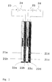
- the four electrolyte chambers 21a-d are filled with NaOH (21a), NaNO 3 (21b), H 2 SO 4 (21c) and NaCl (21d) for pH adjustment.
- the electrodes of the chambers 21a and 21d are connected as cathodes and those of the chambers 21b and 21c as anodes.
- the diffusion barriers comprise an anion exchanger 22a, a cation exchanger 22c and dialysis membranes 22b, 22d.
- the ion exchange membranes or dialysis membranes used have a thickness of approx. 0.5 mm or 0.1 mm. However, other thicknesses can also be selected.
- the switch 24 is closed. If the pH is to be set basic, the switch 26 is closed.
- Other wiring variants and fillings will be selectable by the specialist depending on the requirements. Operation takes place at voltage values which are selected as a function of the setting volume, the conductivity and the design of the device. For the above ranges 2 and 3, the voltage can be less than 100 V, preferably less than 42 V, but can also be higher than 100 V.
- An important advantage for use in laboratory operation is the possibility of operating the device according to the invention with harmless extra-low voltages. In the examples shown, constant current sources were used (voltages around 30V to 60V depending on the operating phase).
- Area 1 is schematic in shown as a sectional view in Fig. 3.
- a compact one Pen for regulating the pH of solution 31 is in a vessel, which is formed here by the beaker 30.
- the pen is designed as a 4-chamber system and contains the following Elements.
- There are four control electrodes 39 a-d to form the Ion currents are provided. Two of which are as anion and cation collectors, the others switched as anion and cation emitters.
- the ion currents pass through the various compartments of the pin 32 a-d, 35 a-d and 36 a-d, the diaphragms or membranes 37 and the solution to be regulated 31.
- the compartments contain further diffusion barriers 35 a-d and degassing openings 310.
- the compartments are with at least 2 different ones Electrolyte solutions filled.
- the pH electrode 34 and Conductivity sensors 33 serve to record the respective actual values when controlling pH or conductivity.
- the sensors may need to be shielded from the control field be (indicated here by the ring 311), or it will worked alternately (measure - regulate). Expediently the solution 31 is mixed (e.g. magnetic stirrer 38).
- the rule pen is with the electronic controlled system 312, the computer interface 313 and the computer or microprocessor 314 connected.
- the system can also be used with a commercial pH measuring and control device can be connected. This allows complicated pH functions be specified (including stairs, jumps, etc.). Farther can go through complicated pH programs at the same time the ion currents required to change the pH be registered and evaluated (similar to the procedure with Titration curves).
- the diaphragms 37 can be formed by a one-piece membrane, which simultaneously the neighboring outputs of the electrolyte areas covered and each attached to the partitions between the electrolyte areas is.
- Area 1 is in the Fig. 4a-c. This example applies to one 3-chamber pen.
- the figures 4a and 4c show two side views (each around 90 Degree offset) of a pH control system according to the invention.
- the Handle part 41, the three chambers (base, acid regulators and Neutral chamber) is on its top through the cap 42 completed.
- Three electrodes are attached to the cap 42 (not shown), each in the chambers in the handle part 41st protrude.
- the electrodes are made up of the feed cable 43 from the electrode leads and the pH electrode wiring (pH electrode not shown), controllable.
- the cap 42 is with Provide ventilation holes that are assigned to the chambers.
- the cap is removable so that the system can be loaded.
- the acid or Base regulators 45 each form a tubular component that on the side facing the neutral phase 44 as diffusion reducing Means has a diaphragm.
- the neutral phase 44 is via a diaphragm to the acid or base regulators 45 completed.
- the diaphragms assigned to the areas 44, 45 have a distance d that is much smaller (e.g. Factor 0.5) as a characteristic variable of the setting volume (e.g. vessel diameter).
- the system can also use three diaphragm cylinders or other geometries.
- the neutral phase 44 can also be divided into two sub-chambers, so that a 4-chamber pin is realized.
- the dimension a is up to 10 mm 500 mm, the dimension b at 10 mm up to 1000 mm and the dimension c at 100 mm up to several meters.
- the distance d varies between 1 mm and 100 mm.
- FIGS. 5a-c An embodiment of the above. Area 2 is shown in FIGS. 5a-c shown.
- 5a pin for volumes of 0.1 ml to 10 ml
- 51 a handle part
- the four chambers Base, acid regulators and neutral chambers
- 52 one Cap or electrode holder
- 53 a cable feed.
- An elongated guide element projects from the underside of the grip part 51 before, into the connecting channels between each electrolyte chamber and the associated diaphragm are integrated in the pyramid Diaphragm head 54, 55 opens.
- the dimension of the diaphragm head 54, 55 is related to the adjustment volume adjusted minimized.
- the diaphragm head 54, 55 is made from four separate diaphragms forming a pyramid shape.
- 54 and 55 denote different types of diaphragms (e.g. dialysis membranes and ion exchange membranes). It is sufficient if at Operation of the device according to the invention by the tip the diaphragm head 54, 55 is formed, immersed in the solution.
- Fig. 5b is a plan view of the handle part with the Diaphragm head 54, 55 shown from below. The four recognize separate diaphragms, two of which in particular at pH control for the feeding of protons and hydroxyl ions are provided. The remaining diaphragms form the phase boundaries to the neutral phases.
- the typical dimensions of a are between 10 mm and 1 mm, from b between 100 mm and 5 mm and from c between 300 mm and 20 mm.
- the dimension d is typically in the range 15 mm to 1 mm selected.
- the mixing of the adjustment solution can over vibration or with very small volumes over Diffusion.
- the application of the amperometric principle leaves downsizing from device components down to ⁇ m size. Generally can part or all of the diaphragms can be dispensed with. On the place of the diaphragms will then be designed accordingly diffusion-inhibiting channels / openings.
- the function of diffusion reducing Means take over three or more capillaries (e.g. glass capillaries with an opening diameter in the um range or below). The strenght Diffusion hindrance through the capillaries allows Omit diaphragms completely.
- Such systems can be used in conjunction with a FET proton sensor (e.g.
- a measurement of 50 ⁇ m x 50 ⁇ m are designed as a capillary complex, which in one Drop of solution is introduced and its pH value is recorded and regulated.
- Preferred areas of application for this version are cell biology, especially those related to the manipulation of egg cells, Techniques related to sperm etc. as well as genetic engineering tasks.
- the system is also suitable for creating pH gradients microscopic expansion.
- Embodiments for the above Area 3 are shown in FIGS. 6 and 7a, 7b.
- the electrolyte regions Chambers are those assigned to the electrolyte regions Chambers, for example, by capillaries or microchannels 61 a-d replaced.
- the arrangement of the chamber systems is expedient and the diaphragms changed.
- a convenient arrangement is the im essential planar grouping of the electrolyte chambers by one central area 66 in which the adjustment solution is located. In this way, very small arrangements can be made generate short response and control times (ms to s range).
- the sensors pH field effect transistor 64 and conductivity sensor 63
- 67 and 68 denote the inflow and outflow, respectively the setting solution.
- Capillary or microchannel openings can be closed again with diaphragms.
- they are also volumetric (in particular spherical) or linear arrangements around the Space possible with the adjustment solution.
- FIG. 7a, 7b An alternative embodiment of a semiconductor technology structured head 71 based on silicon or glass is in the Fig. 7a, 7b.
- the four microchannels taper to one Opening 73 in the chip.
- the tapered form in the miniaturized Design the diffusion reducing agent as a phase boundary between the electrolyte areas and the adjustment solution.
- One on the area of the opening 73 drops of solution in the pH value or in the ion composition can be regulated (pH sensor not shown here).
- the typical dimensions of a are between 2 mm and 1 ⁇ m, at b and c between 50 mm and 100 ⁇ m.
- the size of the system and the very thin tapered capillaries (some with an exit diameter) allow pH adjustment almost without macroscopic Gas evolution at the electrodes.
- the channel openings can run larger when using diffusion-reducing agents are partially filled out.
- the chip can be used as a variant for handling as a compact pen be mounted on a support 74 (FIG. 7b) simultaneously is sub-chambered and contains 3 or 4 types of solution.
- the setting solution is mixed by vibrating the Carrier or also exclusively via diffusion.
- Microvessels can generally be mixed in different ways e.g. by means of a vibrator, by means of a stirrer, by moving the control device itself or by movement of the solution container.
- Size range 1 Another embodiment, preferably with systems of the above Size range 1 is used without being limited to this to be represents the combination of an amperometric Adjustment device with conventional acid-base titrants It is then expedient to use the general control conventionally titratory and fine control amperometric to make.
- the electrolyte chambers contiguous or spaced apart in the walls of containers (beakers, cuvettes, tubes, pipettes or the like.) Integrated.
- the wall then forms the holding means to ensure constant current paths.
- a corresponding one modified device is set up not in the Setting solution to be immersed, but to take it up yourself.
- the containers are easily connected or connected to a control system. detachable.
- This embodiment can be advantageous to use pH-dependent properties of a component of the Adjustment solution (e.g. enzymes), for example optically spectroscopically to investigate by putting the adjustment solution into that Container filled and a pH program is run through.
- the invention Devices designed as flow arrangements. This can be both on the adjustment solution and on the electrolyte chambers Respectively. Due to the high control speed, the Adjustment solution at the phase boundaries to the electrolyte chambers flow past and be adjusted. On the other hand, it is constant renewal of the electrolyte chambers preferred in systems, in which a loss of buffer substance due to redox reactions can be done.
- the flow system of the electrolyte chambers leads at the same time to a reproducible long-term stability of the Control system.
- a pH adjusting device is also specified that Combinations of multiple pH pens in an open or chambered vessel for generating pH values or pH gradients having.
- the electrolyte areas or the corresponding chambers must do not have the same structure, but can have different volumes and / or have shapes.
- the device is not on the Pin shape limited.
- the electrolyte areas can be through suitable dialysis tubes can be realized with inserted control electrodes.
- the dialysis tubes can be clamped in the setting solution.
- the electrolyte areas can be partially connected to one another be so that between the chambers a not to be set Solution can flow migratory current. This makes a comfortable, electrical preconditioning of the chambers is also possible like regeneration (pH adjustment).
- the chambers (especially the neutral phases) can have a common one Have overflow, so that by transferring a small Part of the solution of the respective chamber of the acidic with the basic Share of chambers is mixed.
- This can be different Way, e.g. by inverting the pen and overflowing the chamber, by electroosmosis, in which the volume of a chamber enlarged at the expense of the other chamber by active opening a valve between the chambers, by inserting a diaphragm into the chamber wall by electrolysis in the Gas bubbles generated in electrolyte areas via a channel system be performed and each part of the electrolyte solution take it with you and into another electrolyte area and / or into another one Transfer chambers, or by using a compartmentalized Chamber filling (gel liquid), of which only certain Can mix liquid areas.
- a compartmentalized Chamber filling gel liquid
- Corresponding mixes and volume transfers can also be used for the other chambers, but not between the Donor chambers and the remaining anion / cation acceptor / donor chambers. From this point of view is one or multiple combined anions / cations acceptor / donor chambers preferable because in this type of chamber the acidification or Alkalization again within certain limits by a subsequent one Scheme is lifted.
- the electrolytic Modified composition of the solution to be calibrated become. Should be in place of or next to the actual pH control also ion types are substituted, so for each one to be substituted Ion needs a separate electrolyte chamber. At corresponding number of desired substitutions can Number of electrolyte chambers compared to Fig. 1 much larger to be 3. Conceivable variants then have up to 10 or more individually electrically controllable chambers, each over a diaphragm is connected to the solution to be calibrated. Here, too, inexpensive disposable arrangements can be made realize.
- the device according to the invention can be loaded by the the proton and hydroxyl ion donor chambers and / or the others Pen chambers initially with a similar, uniform Solution that e.g. can also be distilled water be filled and then the system in one loading step operated in a conditioning electrolyte solution until the ion compositions of the electrolyte areas are suitable distinguish in a predetermined manner.
- the loading step follows one programmed procedure, one after the other or at intervals all control electrodes are used, being a measure of progress the procedure uses the currents in the control electrodes become.
- the pen chambers are created by a predefinable control program differ in their ion composition. After that the device can be used for any solution.
- the Running in can also be done in any solution.
- the control behavior and the regulating capacity is something at the beginning worse and improves quickly until stable operation sets.
- the later deterioration due to acidification or overbasing of the donor chambers can be done by the Regeneration device already explained limited or prevented become.
- the setting device can be used as an inexpensive one-way or Exchange system must be set up.
- Interchangeable caps or membranes can be used contain the required membrane areas and just open up the ends of the electrolyte chambers in the form of z. B. of hoses, Allow ducts, pipes, etc. to be plugged on.
- Another variant is a pH stick, in which the diaphragms to be replaced by ion exchange membranes. Through the membrane permeabilities become those contributing to the total flow Ion types reduced in number. This allows pH changes quantified and titration curves via current measurement be preserved. Appropriate enzymatic applications also require temperature control. Hence how in all other applications at least one temperature sensor in the pen be integrated.
- Each of the chambers shown has a phase boundary (e.g. membranes 81 to 85) and a working electrode (86 to 810).
- Diffusion-inhibiting Areas are formed by one of the following measures. It can be a solid area 811 made of gel beads, solid Electrolyte crystallites or the like, a membrane 812 (e.g. an ion exchange membrane), one constriction 813, or a second one, porous, connected to the working electrode via an 815 potentiometer Electrode 814 may be provided.
- Devices according to the invention can be controlled are linked, which specifies the currents through the control electrodes.
- the task of the control loop is in the event of a deviation a positive or negative output current for to provide each control electrode. This stream should Distance to the setpoint.
- PID controller with a control behavior that is made up of a proportional component (P), an integral part (I) and a differential part (D).
- PID controllers are hardware or software related realize. For most routine tasks OPV circuits are sufficient, for more complex regulations one should Calculator can be used.
- the serial computer interface can for recording the pH value and the printer interface use to output the control value.
- anyone can do it PC can be used.
- the control can be done so that the control currents are recorded, displayed and compared with the setpoint, the control currents be kept different in the individual chambers can or the regulation with increasing approximation the setpoint can be refined by reducing the currents can.
- the regulation can be done with the supply of control direct currents can be combined by the circuit.
- the devices according to the invention allow easy cleaning, possibly also sterilization. If necessary, they are cooled and with Currents in the mA to A range can be operated, so that even large volumes in the liter to cubic meter range and more, e.g. Belly swimming pools, aquariums or washing machines can.
- Measures to increase the control speed are e.g. Legs Increasing the concentration of solutions in the chambers, an increase the currents and / or an enlargement of the diaphragms relative to the solution volume.
- the regeneration can be carried out temporarily and / or partially Connection or the continuous or discontinuous Exchange of liquids in the proton donor and Hydroxyl ion donor chambers can be achieved. That can be an overflow be or also include active exchange principles. However, only part of the solution is transferred and none complete mixing sought.
- Regeneration can also be accomplished as follows.
- the two Proton and hydroxyl ion donor chambers for pH control of a Solution are effective if more protons of the a chamber are released into the solution as hydroxyl ions from the other (and vice versa). If the difference is zero, the pH of the solution to be adjusted remains constant. The direction the pH change is due to the dominant chamber fixed.
- the chambers can run continuously or discontinuously a suitable pump system is supplied with fresh electrolyte solution become.
- electrolyte areas e.g. acid and base regulator and the neutral phase
- electrolyte to supply a common storage vessel to which an amperometric Modification means is connected downstream (see FIG. 8).
- the Modifier is provided so that the electrolyte before Filling the individual chambers with a suitable composition having. This creates a dynamic, simply structured, possibly regenerable and easily adaptable to a specific application System formed.
- Electrolyte stream 91 outgoing from the storage vessel becomes partial streams 92 and 93, which acted on the anode 95 and at the cathode 96 are passed.
- a diffusion barrier 97 prevents mixing of the partial streams 92 and 93.
- Charge transport is the substream 93 basic after field passage and the partial stream 92 acidic.
- the partial flow 94 retains its original PH value. With a suitably chosen length of stay in the field you get three electrolyte solutions, each for the Filling an acid regulator, a base regulator and one Neutral phase are suitable.
- Electrolyte regeneration on electronic or mechanical / electrical Way is done either before using the pH device or, if necessary, automatically during operation or in Business breaks.
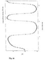
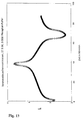
- FIG. 10 A typical pH control with alternating pH increases and Reductions between two extreme values in 100 ml tap water at a current of 250 mA is shown in Fig. 10. With good Mixing the adjustment solution is a shift over a pH unit completed in a few seconds. In the pH range below The control times are extended from pH4 and above pH10 due to the exponentially increasing amount of ions (see also 11 to 13).
- the step curve according to FIG. 12 shows the controllability of the pH in 8 ml of a 10 mmol phosphate buffer solution.
- the pH was lowered by 0.5 pH units each and then for 10 min kept constant.
- the regulation was made to 0.02 pH units I agree. Again, there is a decrease in the middle buffer area the control speed in the "rounding off" of the pH levels.
- the system shown in Fig. 13 is a phosphate buffered (0.05 M) aqueous solution with a volume of 80 ml.
- a cation exchanger at the acid chamber - and at the Base chamber uses an anion exchange membrane.
- the one with the The acid phase operated neutral phase was used to extend the operating time slightly acid buffered, the other neutral phase accordingly kept basic. Shorten the ion exchange membranes the setting times again, up to a factor of approx. 1/2. If you want to make the situation even clearer (e.g. for quantitative recording of the titrated protons or hydroxyl ions), then you also use the first and second neutral phases each the ion-exchanging counter membranes.
- the conductivity of the solution can be changed without any that the control properties are influenced.
- the boundary conditions Control current and buffer properties of the setting solution
- the time for the ions especially pH control. In 14 is this time depending on the volume under consideration shown for different buffer concentrations. Based on a current of 250 mA was used by each Chambers.
Landscapes
- Physics & Mathematics (AREA)
- General Physics & Mathematics (AREA)
- Engineering & Computer Science (AREA)
- Automation & Control Theory (AREA)
- Water Treatment By Electricity Or Magnetism (AREA)
- Control Of Non-Electrical Variables (AREA)
Description
- Säurenregulator:
- H2SO4 (0,01 M), 3 ml
- Basenregulator:
- NaOH (0,01 M), 3 ml
Claims (24)
- Vorrichtung zur amperometrischen Einstellung einer Ionenkonzentration in einer Einstell-Lösung, umfassend:mindestens drei kammerförmige Elektrolytbereiche, die jeweils eine Steuerelektrode und diffusionsmindernde Mittel aufweisen und mit einem Elektrolyten befüllbar sind, wobei die Elektrolytbereiche alle derart mit der Einstell-Lösung in Verbindung bringbar sind, daß bei Stromfluß durch die Steuerelektroden Ionen von den Elektrolyten über die diffusionsmindernden Mittel in die Einstell-Lösung bzw. in umgekehrter Richtung transportierbar sind, undMittel zur Versorgung der Elektrolytbereiche mit Steuerströmen.
- Vorrichtung gemäß Anspruch 1, dadurch gekennzeichnet, daß die Vorrichtung zur Einstellung des pH-Wertes und/oder einer von der Wasserstoffionenkonzentration verschiedenen Ionenkonzentration der Einstell-Lösung eingerichtet ist.
- Vorrichtung gemäß Anspruch 1 oder 2, bei der drei Elektrolytbereiche vorgesehen sind, die umfassen:ein erstes Regulatormittel (A), dessen Elektrolyt als Anionendonator bzw. Basenregulator wirkt und dessen Elektrode eine Kathode ist,ein zweites Regulatormittel (B), dessen Elektrolyt als Kationendonator bzw. Säurenregulator wirkt und dessen Elektrode eine Anode ist, undeine erste Neutralphase (C), deren Elektrolyt entweder als Kationendonator oder als Anionendonator wirkt und deren Elektrode entsprechend als Anode oder als Kathode betreibbar ist oder deren Elektrolyt eine derart hohe Konzentration aufweist, daß die in die Einstell-Lösung transportierbaren H- oder OH-Ionen im Vergleich zum Ionenfluß aus dem ersten und zweiten Regulatormittel vernachlässigbar sind.
- Vorrichtung gemäß Anspruch 3, bei der ein vierter Elektrolytbereich vorgesehen ist, der eine zweite Neutralphase (D) umfaßt, wobeidie erste Neutralphase (C) als Kationendonator wirkt und deren Elektrode als Anode betreibbar ist unddie zweite Neutralphase (D) als Anionendonator wirkt und deren Elektrode als Kathode betreibbar ist, oder der Elektrolyt beider Neutralphasen eine derart hohe Konzentration aufweist, daß die in die Einstell-Lösung transportierbaren H- oder OH-Ionen im Vergleich zum Ionenfluß aus dem ersten und zweiten Regulatormittel vernachlässigbar sind.
- Vorrichtung gemäß einem der Ansprüche 1 bis 4, bei der Haltemittel zur gemeinsamen Halterung von jeweils mindestens zwei oder allen Elektrolytbereichen vorgesehen sind.
- Vorrichtung gemäß Anspruch 5, bei der die gemeinsam gehalterten Elektrolytbereiche aneinandergrenzend angeordnet sind.
- Vorrichtung gemäß Anspruch 6, bei der die gemeinsam gehalterten Elektrolytbereiche so angeordnet sind, daß die diffusionsmindernden Mittel zueinander benachbart sind.
- Vorrichtung gemäß Anspruch 7, bei der die benachbarten diffusionsmindernden Mittel als Diffusionskopf gebildet sind, der in die Einstell-Lösung mindestens partiell eintauchbar oder auf diese aufsetzbar ist.
- Vorrichtung gemäß Anspruch 5, bei der die gemeinsam gehalterten Elektrolytbereiche voneinander beabstandet angeordnet sind.
- Vorrichtung gemäß Anspruch 5, bei der die Haltemittel Teil der Innenwandung eines Behälters zur Aufnahme der Einstell-Lösung sind.
- Vorrichtung gemäß einem der vorhergehenden Ansprüche, bei der mindestens ein Rührmittel vorgesehen ist, mit dem die Einstell-Lösung mischbar ist.
- Vorrichtung gemäß einem der vorhergehenden Ansprüche, bei der mindestens ein Ionen- oder pH-Sensor vorgesehen ist, der simultan mit den Elektrolytbereichen oder getrennt von diesen mit der Einstell-Lösung in Verbindung bringbar ist.
- Vorrichtung gemäß einem der vorhergehenden Ansprüche, bei der die diffusionsmindernden Mittel Gele, Ionenaustauscher, Membranen, Poren, Diaphragmen, mindestens eine Öffnung, die eine Größe im µm-Bereich besitzt, oder weitere Kammern mit bestimmter Ionenzusammensetzung umfassen.
- Vorrichtung gemäß einem der vorhergehenden Ansprüche, bei der mindestens ein Elektrolytbereich einen diffusionsbehindernden Einsatz enthält, der durch Gele, Ionenaustauscher, Membranen, Poren, Diaphragmen, Glaskugeln, Fasern oder festen Elektrolyt gebildet ist und die Elektrode vom diffusionsmindernden Mittel trennt.
- Vorrichtung gemäß einem der vorhergehenden Ansprüche, bei der mindestens ein Elektrolytbereich Belüftungsmittel aufweist, mit denen Gas aus dem Elektrolytbereich herausführbar ist.
- Vorrichtung gemäß einem der vorhergehenden Ansprüche, bei der Regenerierungsmittel zur teilweisen Vermischung des Inhaltes der Elektrolytbereiche oder zum Austausch oder zur Erneuerung des jeweiligen Elektrolyts vorgesehen sind, wobei die Regenerierungsmittel wenigstens eines der folgenden Mittel umfassen:
einen Überlauf, ein Diaphragma, eine strom- und strömungslimitierte Öffnung zwischen den Elektrolytbereichen, oder ein ventilartig steuerbares Uberführungsmittel zum aktiven und dosierten Überführen eines Teils des Inhalts einer oder aller Elektrolytbereiche. - Vorrichtung gemäß einem der vorhergehenden Ansprüche, bei der mindestens ein Elektrolytbereich mehrere Elektroden aufweist, die getrennt mit verschiedenen Strömen ansteuerbar sind.
- Vorrichtung gemäß einem der vorhergehenden Ansprüche, bei der ferner vorgesehen sind:mindestens ein Leitfähigkeitssensor, der mit der Einstell-Lösung in Verbindung gebracht werden kann, und/oderMittel zur Temperaturerfassung und/oder -kompensation,
- Ionen-Einstellgerät, das mindestens eine Vorrichtung gemäß einem der vorhergehenden Ansprüche enthält, wobei jeweils gemeinsam gehalterte Elektrolytbereiche eine kompakte Bauform als Stift, Teller, Kugel, Zylinder, Ellipsoid oder eine andere geschlossene Geometrie bilden, und das mindestens teilweise mit der Einstell-Lösung in Verbindung bringbar, vorzugsweise in die Einstell-Lösung tauchbar, ist.
- Ionen-Einstellgerät gemäß Anspruch 19, das ferner eine oder mehrere der folgenden Einrichtungen enthält:ein Regelsystem zur teilweisen Substituierung oder Hinzufügung einer oder mehrerer Ionenarten unter Verwendung eines weiteren Elektrolytbereiches, der eine Lösung der Ionenart enthält,ein Regelsystem zur Aufnahme von Titrationskurven und zur Korrelation mit chemischen oder biochemischen Reaktionen durch Erfassung oder Konstanthaltung der Lösungszusammensetzung der Elektrolytbereiche und Erfassung der jeweiligen Steuerströme,ein System, bei dem ohne Ionen- oder pH-Sensor allein über die Einstellung der Steuerströme eine Ionenkonzentrations- oder pH-Änderung in einer Lösung erzeugt wird, undeine Vorrichtung zur Säuren- und/oder Basentitration.
- Verfahren zur amperometrischen Einstellung einer Ionenkonzentration einer Einstell-Lösung umfassend die Schritte:Befüllen eines Systems zur amperometrischen Ionenkonzentrations-Einstellung, das mindestens drei kammerförmige Elektrolytbereiche aufweist, die jeweils eine Steuerelektrode und diffusionsmindernde Mittel enthalten, mit einer Vielzahl von Elektrolyten,Verbinden der diffusionsmindernden Mittel der Elektrolytbereiche mit der Einstell-Lösung, undAnsteuern der Elektrolytbereiche mit Steuerströmen, wobei bei Stromfluß durch die Steuerelektroden Ionen von den Elektrolyten über die diffusionsmindernden Mittel derart in die Einstell-Lösung bzw. in umgekehrter Richtung transportiert werden, daß sich die Ionenkonzentration der Einstell-Lösung ändert.
- Verfahren gemäß Anspruch 21, bei dem der pH-Wert und/oder eine von der Wasserstoffionenkonzentration verschiedene Ionenkonzentration der Einstell-Lösung eingestellt wird.
- Verfahren gemäß Anspruch 22, bei dem das Ansteuern als Regelvorgang unter Verwendung eines Ionen- oder pH-Sensors erfolgt.
- Verfahren gemäß Anspruch 23, bei dem in den Regelvorgang ein Lösungswechsel in den Elektrolytbereichen einbezogen wird.
Applications Claiming Priority (9)
| Application Number | Priority Date | Filing Date | Title |
|---|---|---|---|
| DE19542375 | 1995-11-14 | ||
| DE19542375 | 1995-11-14 | ||
| DE19617828 | 1996-05-03 | ||
| DE19617828 | 1996-05-03 | ||
| DE19624150 | 1996-06-18 | ||
| DE19624150 | 1996-06-18 | ||
| DE19634829 | 1996-08-28 | ||
| DE19634829 | 1996-08-28 | ||
| PCT/EP1996/004794 WO1997018503A1 (de) | 1995-11-14 | 1996-11-04 | Vorrichtung und verfahren zur einstellung von ionenkonzentrationen |
Publications (2)
| Publication Number | Publication Date |
|---|---|
| EP0861460A1 EP0861460A1 (de) | 1998-09-02 |
| EP0861460B1 true EP0861460B1 (de) | 1999-09-29 |
Family
ID=27438232
Family Applications (1)
| Application Number | Title | Priority Date | Filing Date |
|---|---|---|---|
| EP96938065A Expired - Lifetime EP0861460B1 (de) | 1995-11-14 | 1996-11-04 | Vorrichtung und verfahren zur einstellung von ionenkonzentrationen |
Country Status (6)
| Country | Link |
|---|---|
| US (1) | US6129832A (de) |
| EP (1) | EP0861460B1 (de) |
| JP (1) | JP2000501173A (de) |
| AU (1) | AU7563296A (de) |
| DE (1) | DE59603244D1 (de) |
| WO (1) | WO1997018503A1 (de) |
Families Citing this family (41)
| Publication number | Priority date | Publication date | Assignee | Title |
|---|---|---|---|---|
| US7096448B2 (en) * | 2001-01-19 | 2006-08-22 | Cadence Design Systems, Inc. | Method and apparatus for diagonal routing by using several sets of lines |
| US20060131161A1 (en) * | 2001-05-07 | 2006-06-22 | Towler Gavin P | Air sanitation with hydrogen peroxide |
| US20060102492A1 (en) * | 2003-02-19 | 2006-05-18 | Corradi Jason T | In situ generation of hydrogen peroxide |
| KR100707191B1 (ko) | 2005-05-25 | 2007-04-13 | 삼성전자주식회사 | 전기투석을 이용한 염 농도 조절 장치, 그를 포함하는랩온어칩 및 그를 이용한 염 농도 조절 방법 |
| KR100647328B1 (ko) | 2005-06-21 | 2006-11-23 | 삼성전자주식회사 | 미세유동 장치 내의 유체의 pH를 전기적으로 조절하기위한 미세유동 장치 및 그를 이용하여 pH를 조절하는방법 |
| KR100657965B1 (ko) | 2005-08-10 | 2006-12-14 | 삼성전자주식회사 | 유체의 pH를 전기화학적으로 조절하기 위한 미세유동장치및 그를 이용하여 pH를 조절하는 방법 |
| KR100738085B1 (ko) * | 2005-12-21 | 2007-07-12 | 삼성전자주식회사 | 유체의 pH를 전기화학적으로 조절하기 위한 미세유동장치및 그를 이용하여 pH를 조절하는 방법 |
| JP2010531732A (ja) | 2007-06-28 | 2010-09-30 | カレラ コーポレイション | 炭酸塩化合物の沈殿を含む脱塩方法 |
| US7753618B2 (en) | 2007-06-28 | 2010-07-13 | Calera Corporation | Rocks and aggregate, and methods of making and using the same |
| US8475639B2 (en) | 2007-12-06 | 2013-07-02 | Dionex Corporation | Titration device and method |
| US7749476B2 (en) | 2007-12-28 | 2010-07-06 | Calera Corporation | Production of carbonate-containing compositions from material comprising metal silicates |
| JP2012513944A (ja) * | 2007-12-28 | 2012-06-21 | カレラ コーポレイション | Co2を捕捉する方法 |
| US20100239467A1 (en) | 2008-06-17 | 2010-09-23 | Brent Constantz | Methods and systems for utilizing waste sources of metal oxides |
| US7754169B2 (en) | 2007-12-28 | 2010-07-13 | Calera Corporation | Methods and systems for utilizing waste sources of metal oxides |
| US7993500B2 (en) | 2008-07-16 | 2011-08-09 | Calera Corporation | Gas diffusion anode and CO2 cathode electrolyte system |
| EP2212033A4 (de) | 2008-07-16 | 2013-04-24 | Calera Corp | Vierzelliges elektrochemisches niedrigenergiesystem mit kohlendioxidgas |
| KR20110038691A (ko) | 2008-07-16 | 2011-04-14 | 칼레라 코포레이션 | 전기화학 시스템에서 co2를 사용하는 방법 |
| AU2009287461A1 (en) | 2008-09-11 | 2010-04-08 | Calera Corporation | CO2 commodity trading system and method |
| TW201026597A (en) | 2008-09-30 | 2010-07-16 | Calera Corp | CO2-sequestering formed building materials |
| US8869477B2 (en) | 2008-09-30 | 2014-10-28 | Calera Corporation | Formed building materials |
| US7815880B2 (en) | 2008-09-30 | 2010-10-19 | Calera Corporation | Reduced-carbon footprint concrete compositions |
| US7939336B2 (en) | 2008-09-30 | 2011-05-10 | Calera Corporation | Compositions and methods using substances containing carbon |
| US9133581B2 (en) | 2008-10-31 | 2015-09-15 | Calera Corporation | Non-cementitious compositions comprising vaterite and methods thereof |
| WO2010051458A1 (en) | 2008-10-31 | 2010-05-06 | Calera Corporation | Non-cementitious compositions comprising co2 sequestering additives |
| BRPI0823394A2 (pt) * | 2008-12-23 | 2015-06-16 | Calera Corp | Sistema e método eletroquímico de hidróxido de baixa energia |
| AU2010201005A1 (en) | 2009-02-10 | 2010-08-26 | Calera Corporation | Low-voltage alkaline production using hydrogen and electrocatlytic electrodes |
| CA2694959A1 (en) | 2009-03-02 | 2010-09-02 | Calera Corporation | Gas stream multi-pollutants control systems and methods |
| TW201105406A (en) | 2009-03-10 | 2011-02-16 | Calera Corp | Systems and methods for processing CO2 |
| US7993511B2 (en) | 2009-07-15 | 2011-08-09 | Calera Corporation | Electrochemical production of an alkaline solution using CO2 |
| CN102240843B (zh) * | 2011-06-29 | 2012-12-26 | 张家港市安捷探伤焊割设备修造厂 | 一种大直径拉弧式螺柱焊枪 |
| WO2013028924A1 (en) | 2011-08-23 | 2013-02-28 | Board Of Regents, The University Of Texas System | Electrolytic buffer generator |
| US9567678B2 (en) | 2011-08-29 | 2017-02-14 | Massachusetts Institute Of Technology | Methods and systems for carrying out a pH-influenced chemical and/or biological reaction |
| WO2013033173A1 (en) | 2011-08-29 | 2013-03-07 | Massachusetts Institute Of Technology | METHODS AND SYSTEMS FOR CARRYING OUT A pH-INFLUENCED CHEMICAL AND/OR BIOLOGICAL REACTION |
| US9766207B2 (en) | 2011-11-04 | 2017-09-19 | Bio-Rad Laboratories, Inc. | Affinity methods and compositions employing electronic control of pH |
| WO2013067509A1 (en) | 2011-11-04 | 2013-05-10 | Bio-Rad Laboratories, Inc. | Simultaneous purification of cell components |
| WO2013123425A1 (en) | 2012-02-15 | 2013-08-22 | Bio-Rad Laboratories, Inc. | Electronic control of ph and ionic strength |
| US9321012B2 (en) | 2012-04-04 | 2016-04-26 | Bio-Rad Laboratories, Inc. | Electronic protein fractionation |
| US10656118B2 (en) * | 2017-02-02 | 2020-05-19 | Ika-Werke Gmbh & Co. Kg | Closure for an electrochemical vessel, electrochemical vessel and laboratory device |
| CN111031896A (zh) * | 2017-06-21 | 2020-04-17 | 外分泌腺系统公司 | 具有ph缓冲的eab传感器的生物流体感测装置 |
| CN112576673B (zh) * | 2019-09-27 | 2022-11-25 | 北京金风科创风电设备有限公司 | 调频阻尼器、风力发电机组及调频阻尼器的调频方法 |
| CN120187870A (zh) * | 2022-09-19 | 2025-06-20 | 伊莱克特拉钢铁有限公司 | 电化学冶金炉渣回收 |
Family Cites Families (9)
| Publication number | Priority date | Publication date | Assignee | Title |
|---|---|---|---|---|
| GB1177693A (en) * | 1966-05-17 | 1970-01-14 | Valmet Oy | Improvements in Methods of and Devices for Regulating the pH Values of Boiler Feed Water by Electrolytic Action |
| DE2114395A1 (en) * | 1971-03-25 | 1972-10-05 | Herty I | Products with any desired ph value - harmonising partic medically and therapeutically with inherent differences in human make-up |
| JPS5362637A (en) * | 1976-11-12 | 1978-06-05 | Matsushita Electric Industrial Co Ltd | Automatic controlling method and device for ph of culture solution |
| JPS589651B2 (ja) * | 1979-03-29 | 1983-02-22 | 松下電器産業株式会社 | 培養液ph値調節装置 |
| GB2058409A (en) * | 1979-09-07 | 1981-04-08 | Nat Res Dev | Controlling ph or ion concentration of a stream |
| US5278132A (en) * | 1986-02-11 | 1994-01-11 | Gouws & Scheepers (Propietary) Ltd. | Agricultural compounds |
| US4936962A (en) * | 1989-03-01 | 1990-06-26 | Fmc Corporation | Process for adjusting the pH of an aqueous flowable fluid |
| FR2645292A1 (fr) * | 1989-03-30 | 1990-10-05 | Morgane | Procede et installation de regulation du ph d'un milieu reactionnel par electrodialyse |
| GB9413525D0 (en) * | 1994-07-05 | 1994-08-24 | Unilever Plc | Improvements in or relating to electrochemical instruments |
-
1996
- 1996-11-04 DE DE59603244T patent/DE59603244D1/de not_active Expired - Lifetime
- 1996-11-04 WO PCT/EP1996/004794 patent/WO1997018503A1/de not_active Ceased
- 1996-11-04 EP EP96938065A patent/EP0861460B1/de not_active Expired - Lifetime
- 1996-11-04 AU AU75632/96A patent/AU7563296A/en not_active Abandoned
- 1996-11-04 US US09/068,764 patent/US6129832A/en not_active Expired - Lifetime
- 1996-11-04 JP JP9518543A patent/JP2000501173A/ja active Pending
Also Published As
| Publication number | Publication date |
|---|---|
| WO1997018503A1 (de) | 1997-05-22 |
| JP2000501173A (ja) | 2000-02-02 |
| DE59603244D1 (de) | 1999-11-04 |
| AU7563296A (en) | 1997-06-05 |
| US6129832A (en) | 2000-10-10 |
| EP0861460A1 (de) | 1998-09-02 |
Similar Documents
| Publication | Publication Date | Title |
|---|---|---|
| EP0861460A1 (de) | Vorrichtung und verfahren zur einstellung von ionenkonzentrationen | |
| EP0273258B1 (de) | Anordnung zur Untersuchung eines flüssigen Mediums und Verfahren zum Betrieb der Anordnung | |
| DE69428702T2 (de) | Vorrichtung zum analysieren eines fluiden mediums | |
| EP0016415B1 (de) | Verfahren zum Messen und Regeln der Konzentration von Kupfer, Formaldehyd und Natronlauge in einem Bad zum stromlosen Abscheiden von Kupfer, sowie Probennahmevorrichtung zur Verwendung bei diesem Verfahren | |
| DE102011007011B4 (de) | Analysegerät zur automatisierten Bestimmung einer Messgröße einer Flüssigkeitsprobe und Verfahren zur Überwachung einer Messgröße | |
| DE2645503A1 (de) | Verfahren und vorrichtung fuer die automatische verfahrenstitration | |
| EP0754944A1 (de) | Verfahren zur Qualitätskontrolle eines portablen Analysensystems sowie Flüssigkeit zur Durchführung des Verfahrens | |
| EP0122420A2 (de) | Elektrodenanordnung zur elektrochemischen Analyse elektrolytischer Bestandteile einer Flüssigkeit | |
| EP1178315A1 (de) | Verfahren und Vorrichtung zur Untersuchung von Zellen mit Hilfe der Patch Clamp-Methode | |
| DE112018005405T5 (de) | REGELUNG DES pH-WERTES ZUM DETEKTIEREN VON ANALYTEN | |
| CH669607A5 (de) | ||
| DE9421730U1 (de) | Vorrichtung zum Analysieren eines Fluidmediums | |
| EP0574354A1 (de) | Körper für die Bildung mindestens einer Elektrode und/oder eines Sensors | |
| DE2265200C3 (de) | Strömungszelle für Zwecke der elektrochemischen Analyse | |
| EP2669677B1 (de) | Verfahren und Vorrichtung zur Beschleunigung der Äquilibrierung einer Flüssigkeit | |
| DE2147725A1 (de) | Vorrichtung zum Bestimmen des Sauerstoffbedarfs in Flüssigkeitsproben | |
| DE3100302A1 (de) | Elektrochemische referenzelektrode | |
| WO2003049841A1 (de) | Vorrichtung zur simultanen dialyse einer vielzahl flüssiger proben | |
| EP4007912B1 (de) | Mobile anlage für das kalibrieren, verifizieren und/oder justieren eines sensors und verfahren zum kalibrieren, verifizieren und/oder justieren eines sensors | |
| AT391215B (de) | Messgeraet zur erfassung chemischer parameter einer waessrigen probe | |
| EP2156890B1 (de) | Anordnung und Verfahren zum Erzeugen, Manipulieren und Analysieren von Kompartimenten | |
| DE102011113941B4 (de) | Elektrochemische Messkette | |
| DE69929686T2 (de) | Verfahren zum messen der nitrifikationsraten in biochemischen prozessen | |
| DE60118533T2 (de) | Analytischer Mikrochip mit Eingabe- und Ausgabeleitungen zwischen Wanne und Behälter | |
| EP0262582B1 (de) | Verfahren zur Bestimmung des Konzentrationsverhältnisses von Lithiumionen zu Natriumionen und Vorrichtung zur Durchführung dieses Verfahrens |
Legal Events
| Date | Code | Title | Description |
|---|---|---|---|
| PUAI | Public reference made under article 153(3) epc to a published international application that has entered the european phase |
Free format text: ORIGINAL CODE: 0009012 |
|
| 17P | Request for examination filed |
Effective date: 19980513 |
|
| AK | Designated contracting states |
Kind code of ref document: A1 Designated state(s): CH DE GB LI |
|
| GRAG | Despatch of communication of intention to grant |
Free format text: ORIGINAL CODE: EPIDOS AGRA |
|
| 17Q | First examination report despatched |
Effective date: 19981120 |
|
| GRAG | Despatch of communication of intention to grant |
Free format text: ORIGINAL CODE: EPIDOS AGRA |
|
| GRAH | Despatch of communication of intention to grant a patent |
Free format text: ORIGINAL CODE: EPIDOS IGRA |
|
| GRAH | Despatch of communication of intention to grant a patent |
Free format text: ORIGINAL CODE: EPIDOS IGRA |
|
| GRAA | (expected) grant |
Free format text: ORIGINAL CODE: 0009210 |
|
| AK | Designated contracting states |
Kind code of ref document: B1 Designated state(s): CH DE GB LI |
|
| REG | Reference to a national code |
Ref country code: CH Ref legal event code: EP |
|
| REF | Corresponds to: |
Ref document number: 59603244 Country of ref document: DE Date of ref document: 19991104 |
|
| GBT | Gb: translation of ep patent filed (gb section 77(6)(a)/1977) |
Effective date: 19991221 |
|
| REG | Reference to a national code |
Ref country code: CH Ref legal event code: NV Representative=s name: DIPL.-ING. ETH H. R. WERFFELI PATENTANWALT |
|
| PLBE | No opposition filed within time limit |
Free format text: ORIGINAL CODE: 0009261 |
|
| STAA | Information on the status of an ep patent application or granted ep patent |
Free format text: STATUS: NO OPPOSITION FILED WITHIN TIME LIMIT |
|
| 26N | No opposition filed | ||
| REG | Reference to a national code |
Ref country code: GB Ref legal event code: IF02 |
|
| PGFP | Annual fee paid to national office [announced via postgrant information from national office to epo] |
Ref country code: CH Payment date: 20121126 Year of fee payment: 17 Ref country code: DE Payment date: 20121128 Year of fee payment: 17 |
|
| PGFP | Annual fee paid to national office [announced via postgrant information from national office to epo] |
Ref country code: GB Payment date: 20121126 Year of fee payment: 17 |
|
| REG | Reference to a national code |
Ref country code: CH Ref legal event code: PL |
|
| GBPC | Gb: european patent ceased through non-payment of renewal fee |
Effective date: 20131104 |
|
| PG25 | Lapsed in a contracting state [announced via postgrant information from national office to epo] |
Ref country code: CH Free format text: LAPSE BECAUSE OF NON-PAYMENT OF DUE FEES Effective date: 20131130 Ref country code: LI Free format text: LAPSE BECAUSE OF NON-PAYMENT OF DUE FEES Effective date: 20131130 |
|
| REG | Reference to a national code |
Ref country code: DE Ref legal event code: R119 Ref document number: 59603244 Country of ref document: DE Effective date: 20140603 |
|
| PG25 | Lapsed in a contracting state [announced via postgrant information from national office to epo] |
Ref country code: DE Free format text: LAPSE BECAUSE OF NON-PAYMENT OF DUE FEES Effective date: 20140603 |
|
| PG25 | Lapsed in a contracting state [announced via postgrant information from national office to epo] |
Ref country code: GB Free format text: LAPSE BECAUSE OF NON-PAYMENT OF DUE FEES Effective date: 20131104 |