EP0861733A2 - Abdeckender Flüssigkeitsbehälter und Kappe - Google Patents
Abdeckender Flüssigkeitsbehälter und Kappe Download PDFInfo
- Publication number
- EP0861733A2 EP0861733A2 EP98102815A EP98102815A EP0861733A2 EP 0861733 A2 EP0861733 A2 EP 0861733A2 EP 98102815 A EP98102815 A EP 98102815A EP 98102815 A EP98102815 A EP 98102815A EP 0861733 A2 EP0861733 A2 EP 0861733A2
- Authority
- EP
- European Patent Office
- Prior art keywords
- liquid container
- cap
- engagement means
- capped
- container according
- Prior art date
- Legal status (The legal status is an assumption and is not a legal conclusion. Google has not performed a legal analysis and makes no representation as to the accuracy of the status listed.)
- Granted
Links
- 239000007788 liquid Substances 0.000 title claims abstract description 297
- 238000003466 welding Methods 0.000 claims description 117
- 238000001125 extrusion Methods 0.000 claims description 64
- 230000000717 retained effect Effects 0.000 claims description 8
- 239000011295 pitch Substances 0.000 claims description 6
- 239000000463 material Substances 0.000 claims description 5
- 229920005992 thermoplastic resin Polymers 0.000 claims description 5
- 238000000748 compression moulding Methods 0.000 claims 1
- 238000000465 moulding Methods 0.000 claims 1
- 238000007789 sealing Methods 0.000 abstract description 22
- 230000000694 effects Effects 0.000 abstract description 14
- XLYOFNOQVPJJNP-UHFFFAOYSA-N water Substances O XLYOFNOQVPJJNP-UHFFFAOYSA-N 0.000 abstract description 10
- 230000001066 destructive effect Effects 0.000 description 4
- 230000006835 compression Effects 0.000 description 3
- 238000007906 compression Methods 0.000 description 3
- 230000035939 shock Effects 0.000 description 3
- 230000015572 biosynthetic process Effects 0.000 description 2
- 230000008878 coupling Effects 0.000 description 2
- 238000010168 coupling process Methods 0.000 description 2
- 238000005859 coupling reaction Methods 0.000 description 2
- 238000004519 manufacturing process Methods 0.000 description 2
- 238000003825 pressing Methods 0.000 description 2
- 230000002265 prevention Effects 0.000 description 2
- 239000004743 Polypropylene Substances 0.000 description 1
- 238000013459 approach Methods 0.000 description 1
- 229920001971 elastomer Polymers 0.000 description 1
- 239000000806 elastomer Substances 0.000 description 1
- 238000002474 experimental method Methods 0.000 description 1
- 238000001746 injection moulding Methods 0.000 description 1
- 238000000034 method Methods 0.000 description 1
- -1 polypropylene Polymers 0.000 description 1
- 229920001155 polypropylene Polymers 0.000 description 1
- 229920005989 resin Polymers 0.000 description 1
- 239000011347 resin Substances 0.000 description 1
- 238000000926 separation method Methods 0.000 description 1
- 238000010008 shearing Methods 0.000 description 1
- 238000009751 slip forming Methods 0.000 description 1
- 238000010186 staining Methods 0.000 description 1
- 239000000126 substance Substances 0.000 description 1
- 230000002459 sustained effect Effects 0.000 description 1
- 238000005303 weighing Methods 0.000 description 1
Images







Classifications
-
- B—PERFORMING OPERATIONS; TRANSPORTING
- B41—PRINTING; LINING MACHINES; TYPEWRITERS; STAMPS
- B41J—TYPEWRITERS; SELECTIVE PRINTING MECHANISMS, i.e. MECHANISMS PRINTING OTHERWISE THAN FROM A FORME; CORRECTION OF TYPOGRAPHICAL ERRORS
- B41J2/00—Typewriters or selective printing mechanisms characterised by the printing or marking process for which they are designed
- B41J2/005—Typewriters or selective printing mechanisms characterised by the printing or marking process for which they are designed characterised by bringing liquid or particles selectively into contact with a printing material
- B41J2/01—Ink jet
- B41J2/17—Ink jet characterised by ink handling
- B41J2/175—Ink supply systems ; Circuit parts therefor
- B41J2/17503—Ink cartridges
- B41J2/17536—Protection of cartridges or parts thereof, e.g. tape
-
- B—PERFORMING OPERATIONS; TRANSPORTING
- B41—PRINTING; LINING MACHINES; TYPEWRITERS; STAMPS
- B41J—TYPEWRITERS; SELECTIVE PRINTING MECHANISMS, i.e. MECHANISMS PRINTING OTHERWISE THAN FROM A FORME; CORRECTION OF TYPOGRAPHICAL ERRORS
- B41J2/00—Typewriters or selective printing mechanisms characterised by the printing or marking process for which they are designed
- B41J2/005—Typewriters or selective printing mechanisms characterised by the printing or marking process for which they are designed characterised by bringing liquid or particles selectively into contact with a printing material
- B41J2/01—Ink jet
- B41J2/17—Ink jet characterised by ink handling
- B41J2/175—Ink supply systems ; Circuit parts therefor
- B41J2/17503—Ink cartridges
- B41J2/1752—Mounting within the printer
- B41J2/17523—Ink connection
Definitions
- the present invention relates to a capped liquid container that retains liquid to be supplied to the recording devices of an ink jet recording apparatus.
- the invention also relates to a cap.
- the liquid used as a recording liquid for an ink jet recording apparatus is retained in a liquid container.
- the liquid container is unsealed when new recording liquid should be filled into an ink jet recording apparatus. Then, the liquid retained in the liquid container is ready to use.
- the description will be made of the conventional liquid container with a cap attached to it for use of an ink jet recording apparatus.
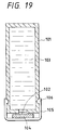
- Fig. 19 is a cross-sectional view which shows the conventional liquid container with a cap attached to it.
- the conventional liquid container having the cap attached to it is provided with a supply opening 102 on the liquid container 101 serving as a container to retain liquid in it.
- An elastic plate member 104 is pressed from outside the container by means of a cap external member 105 so that it abuts upon this supply opening 102, thus sealing the liquid container 101 to retain liquid inside the container.
- the cap external member 105 is arranged to extend vertically along both sides of the container from both edges of the surface. The elastic plate member 104 is then pressed to abut upon the supply opening 102.
- the click nail 106 On each face of the leading ends of the cap external member, which is in contact with the liquid container, the click nail 106 is formed. Also, grooves are formed on the side faces of the liquid container 101 to engage with the click nails 106, respectively. In this manner, with the elastic plate member 104 sandwiched between the supply opening 102 and the cap external member 105, the click nails 106 are caused to engage with the grooves of the liquid container 101, thus hooking the cap external member 105 to the liquid container 101. Now, the liquid container 101 will be described further in detail.
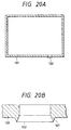
- Figs. 20A and 20B are cross-sectional views which illustrate the liquid container 101 represented in Fig. 19.
- Fig. 20A shows the entire body of the liquid container 101.
- Fig. 20B is an enlarged view of the supply opening shown in Fig. 20A.
- the supply opening 102 extrudes from one face of the liquid container 101.
- the leading end of the extruded supply opening 102 has an acutely angled portion 107 as shown in Fig. 20B.
- the elastic plate member 104 is pressed to abut upon this acutely angled portion 107 at the leading end of the supply opening 102.
- the acutely angled portion 107 is arranged to bite in the elastic plate member 104 to produce the sealing effect on the contact surface between the supply opening 102 and the elastic plate member 104.
- the liquid container 101 is sealed to retain liquid 103 in it.
- the present invention is designed with a view to solving the problems existing in the conventional art. It is an object of the invention to provide a capped liquid container whose cap that closes the supply opening formed for the liquid container has a lesser degree of creep deformation or the like and provides a higher water tightness and air tightness when recording liquid or the like is retained in the liquid container for use of an ink jet recording apparatus.
- the capped liquid container of the present invention comprises a liquid container retaining liquid, having a supply opening formed for supplying the liquid to the recording devices of an ink jet recording apparatus; and a cap fixed to the liquid container for closing the supply opening, the cap being removed from the liquid container by rotating the cap.
- This cap is formed by a rigid member and an elastic member, and the elastic member is provided with first engagement means, and second engagement means is formed on the edge circumference of the supply opening to engage with the first engagement means. Then, the first engagement means and the second engagement means are pressed to be joined together, and at the same time, a part of the rigid member of the cap is fixed to the liquid container.
- the cap of the present invention is arranged to close a liquid container.
- This cap is fixed to the supply opening of the liquid container for supplying liquid retained in the liquid container to the recording devices of an ink jet recording apparatus.
- the cap is formed by a rigid member and an elastic member. Then, first engagement means which is provided for the elastic member is pressed to join second engagement means which is provided for the supply opening, and at the same time, a part of the rigid member of the cap is fixed to the liquid container.
- the liquid container of the present invention is arranged to retain liquid, having a supply opening formed for supplying the liquid to the recording devices of an ink jet recording apparatus. Then, a cap is fixed to the supply opening for closing the liquid container, and removed from the liquid container by rotating the cap. Also, the supply opening is provided with second engagement means to engage with first engagement means provided for this cap. The second engagement means is pressed to join the first engagement means.
- a capped liquid container of the present invention comprises a liquid container having a supply opening formed for it; and a cap fixed to the liquid container for closing the supply opening airtightly.
- the cap is removed from the liquid container when it is rotated to unseal the capped liquid container.
- the cap is formed by a rigid member and an elastic member.
- First engagement means is provided for the elastic member, and second engagement means is provided for the edge circumferential portion of the supply opening to engage with the first engagement means.
- the first and second engagement means are pressed to be joined together.
- a part of the rigid member of the cap is fixed to the liquid container.
- the elastic first engagement means is deformed to agree with the compressed shape of the contact surface of the second engagement means, thus the contact surface between the first and second engagement means produces the sealing effect to close the liquid container.
- a part of the rigid member of the cap is fixed to the liquid container, thus making it difficult to cause creep deformation even when stress is exerted on the rigid member by the pressurized contact between the first and second engagement means.
- the cap fixed to the liquid container is removed by the application of shearing force exerted by the rotation of the cap. Therefore, no external force is given to side faces of the liquid container when the cap is open. There is no possibility that liquid in the interior of the liquid container is caused to spread.
- Fig. 1A is an upper surface view which shows a capped liquid container in accordance with a first embodiment of the present invention.
- Fig. 1B is a front view which shows the capped liquid container represented in Fig. 1A.
- Figs. 2A, 2B and 2C are the upper surface, side, and bottom views which illustrate the cap represented in Figs. 1A and 1B, respectively.
- Figs. 3A and 3B are the enlarged bottom and cross-sectional views which illustrate the portion of the cylindrical outer unit of the cap represented in Figs. 2A, 2B and 2C respectively.
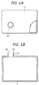
- Figs. 4A and 4B are the upper surface and cross-sectional views which illustrate the liquid container represented in Figs. 1A and 1B.
- Figs. 5A, 5B and 5C are the enlarged upper surface and cross-sectional views which illustrate a part of the liquid supply unit of the liquid container represented in Figs. 4A and 4B, respectively.
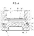
- Fig. 6 is a cross-sectional view which shows the relationship of engagement between first and second means for engagement embodying the present invention.
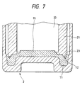
- Fig. 7 is a cross-sectional view which shows the state of the cap that engages with the liquid supply unit represented in Fig. 6.
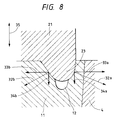
- Fig. 8 is an enlarged sectional view which shows the contact surface between the V groove and the extrusion represented in Fig. 7.
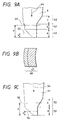
- Figs. 9A, 9B and 9C are views which illustrate the welding portion of the cap represented in Figs. 3A and 3B.
- Fig. 10 is a view which shows the relationship between the welding stroke and welding area, and the welding stroke and unsealing force exerted by the rotation of the cap with respect to the welding portion represented in Figs. 9A, 9B and 9C.
- Fig. 11 is a view which shows the arrangement of the welding portions of the cap represented in Figs. 3A and 3B.
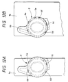
- Figs. 12A and 12B are the upper surface views which illustrate the states where the cap represented in Fig. 11 is welded on the liquid container having a narrower bottom, and on the liquid container having a wider bottom, respectively.
- Fig. 13 is a cross-sectional view which shows a capped liquid container most appropriately in accordance with a second embodiment of the present invention.
- Fig. 14 is a cross-sectional view which shows the state of engagement between the V grooves and extrusion represented in Fig. 13.
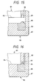
- Fig. 15 is a cross-sectional view which shows a capped liquid container most appropriately in accordance with a third embodiment of the present invention.
- Fig. 16 is a cross-sectional view which shows the state of engagement between the V groove and extrusion representing in Fig. 15.
- Fig. 17 is a cross-sectional view which shows a capped liquid container most appropriately in accordance with a fourth embodiment of the present invention.
- Fig. 18 is a cross-sectional view which shows the state of engagement between the V grooves and extrusions represented in Fig. 17.
- Fig. 19 is a cross-sectional view which shows a capped liquid container in accordance with the conventional art.
- Fig. 20A is a cross-sectional view which shows the liquid container represented in Fig. 19.
- Fig. 20B is an enlarged sectional view which shows the portion of the supply opening of the liquid container represented in Fig. 20A.
- Fig. 1A is the upper surface view which shows a capped liquid container in accordance with a first embodiment of the present invention.
- Fig. 1B is the front view thereof.
- the capped liquid container 1 of the present embodiment retains in it liquid 3 used for recording by means of an ink jet recording apparatus.
- a supply opening 22 is formed on the upper surface of the liquid container 1 for supplying the liquid 3 to the recording devices of the ink jet recording apparatus.
- a cap 2 is firmly fixed to the supply opening 22 in order to retain liquid in the liquid container 1.
- a plurality of welding portions 6 are formed on the edge of the cylindrical portion of the cap 2 to extrude toward the liquid container 1. Then, each of the welding portions 6 is in contact with the liquid container 1. These portions 6 and the contact surface of the liquid container 1 are welded by means of ultrasonic welding.
- the sealed liquid container 1 is unsealed by rotating the cap 2 to shear the welding portions 6.
- the cap 2 is then removed from the liquid container 1. Therefore, unlike the conventional one, the capped liquid container of the present embodiment does not need any grooves for the engagement of the cap external member with the liquid container. Also, the cap 2 is removed from the liquid container 1 by rotating the cap 2 when the liquid container 1 is unsealed. Therefore, unlike the conventional one, there is no possibility that any external force acts upon the side faces of the liquid container so as to press them inwardly when the liquid container is unsealed. As a result, the liquid container 1 can be unsealed without allowing the liquid 3 in the liquid container 1 to spread externally. Also, the container can be open easily. In this manner, it is possible to materialize a capped liquid with a good unsealing operativity.
- Figs. 2A to 2C are the upper surface, side, and bottom views of the cap shown in Figs. 1A and 1B, respectively.
- the cap 2 is structured in such a manner that a curved handle 5a and a handle 5b which is smaller than the handle 5a are formed on a cylindrical outer member 4 that serves as a rigid body to cover the supply opening of the liquid container 1.
- the cylindrical outer member 4 is placed between the handles.
- a plurality of welding portions 6 protrude on the edge of the leading end of the cylindrical outer member 4 on the liquid container 1 side in order to fix the cap 2 firmly to the liquid container 1.
- Each of the welding portion 6 is arranged on the circumference of the edge of the cylindrical outer member 4 at locally different pitches.
- an arrow mark 7 is impressed to indicate the rotational direction of the cap 2.
- knurling 8 is provided for the slip prevention.
- Fig. 3A is the enlarged bottom views of the portion of the cylindrical outer member 4 of the cap 2 shown in Figs. 2A to 2C.
- Fig. 3B is a cross-sectional view taken along line 3B - 3B in Fig. 3A.
- one bottom side of the cylindrical outer member 4 namely, the reverse side thereof, is open.
- the central part of the other bottom side is in a form that rises inwardly to the interior of the cylindrical outer member 4.
- An elastic member 11 is formed on the bottom face of the interior of the cylindrical outer member 4, as well as its raised portion in the central part of this member.
- a V groove 12 is continuously formed in circle as first engagement means provided for the inner side of the outer circumference of the elastic member 11.
- an overly truncated cone extrusion 13 is arranged to slightly protrude with the inclined surface 14 provided also in the form of the overly truncated cone.
- a cylindrical inner plug 15 is arranged to protrude from the end face of the overly truncated cone extrusion 13.
- Fig. 4A is the upper view which shows the liquid container represented in Figs. 1A and 1B.
- Fig. 4B is a cross-sectional view which shows the liquid container, observed from the front.
- a hollow cylindrical liquid supply portion 21 is arranged to protrude extensively for the supply of liquid retained in the liquid container to the recording devices of an ink jet recording apparatus.
- the surface of the leading end of the liquid supply portion 21 is formed to be the supply opening 22.
- the hollow section of the liquid supply portion 21 serves as the supply path 20. Through the supply path 20, the interior of the liquid container 1 is conductively connected with the supply opening 22.
- the liquid supply portion 21 is covered by the cap 2 to close the supply opening 22, thus sealing the liquid container 1.
- Fig. 5A is the enlarged upper view which shows the extruded leading end of the liquid supply portion 21 of the liquid container 1 represented in Figs. 4A and 4B.
- Fig. 5B is a cross-sectional view which shows the portion represented in Fig. 5A, observed from the front.
- Fig. 5C is a cross-sectional view thereof, observed from the side.
- an extrusion 6 is formed in circle, which protrudes semi-circularly as second engagement means to engage with the V groove 12 on the cap 2.
- an elongated circular opening 25 is formed in the interior of the liquid supply portion 21 on the base of the extrusion 6.
- an inclined surface 24 is formed to engage with the inclined surface 24 of the cap 2, which is provided in the form of the overly truncated cone as described earlier.
- Fig. 6 is a cross-sectional view illustrating the relationship of engagement between them in the state before the liquid supply portion 21 and the cap 2 are in contact with each other.
- the diameter D of the semi-circular extrusion 23 formed on the leading end of the liquid supply portion 21 is made larger than the width W of the V groove 12.
- the V groove 12 and the extrusion 23 are pressed to be in contact.
- each of the opening ends of the V groove 12 is formed as a curved surface as indicated at 31a and 31b, respectively.
- Each of the curved surfaces 31a and 31b serves as guide for the extrusion 23 when the extrusion 23 is pressed to abut upon the V groove 12.
- the bottom of the V groove 12 is curved as indicated at 31c. Now, the description will be made of the state where the extrusion 23 and V groove 12 thus configured are pressed to be in contact.
- Fig. 7 is a cross-sectional view which shows the state where the extrusion 23 and the V groove 12 are pressed to be in contact with each other from the state represented in Fig. 6.
- the extrusion 23 presses the V groove 21 to make it wider, and then, the extrusion 23 is fitted into the groove 12.
- the surface of the V groove 21 which is in contact with the extrusion 23 is deformed to follow the curved surface of the extrusion 23. Therefore, the surfaces of the extrusion 23 and V groove 12 are closely in contact. This close contact between the inclined surfaces on the extrusion 23 and V groove 12 produces the sealing effect on the supply opening 22.
- the inclined surface 14 of the cap 2 in the form of the oval truncated cone, and the inclined surface 24 of the liquid supply portion 21 produces the sealing effect on the liquid container 1 when these inclined surfaces are put together.
- the inner plug 15 of the cap 2 is inserted into the elongated opening 25 of the liquid supply portion 21, thus protruding to the interior of the liquid supply portion 21.
- the bottom of the V groove 12 is curved as indicated at 31c. Therefore, the stress which is intensively exerted on the bottom of the V groove 12 is eased when the V groove 12 is made wider by pressure. In this manner, the V groove 12 is prevented from being cracked.
- the description will be made of the relationship between the forces acting upon the contact surface of the V groove 12 and extrusion 23 represented in Fig. 7.
- Fig. 8 is an enlarged sectional view which shows a part of the contact surface of the V groove 12 and extrusion 23 represented in Fig. 7.
- each of the compressions 32a and 32b are exerted by the extrusion 23 on the contact planes on both sides of the V groove 12 which is deformed to be wider by the pressure exerted by the extrusion 23.
- the compressions 32a and 32b are divided into the components 33a and 33b in the directions perpendicular to the directions 35 of the supply path, as well as divided into the components 34a and 34b in the direction parallel to the directions 35 of the supply path.
- Each of the components 22a and 33b is the forces whereby the extrusion 23 presses the V groove 12 to make it wider.
- the cylindrical outer member 4 receives the component 33a, while the inner plug 25 receives the component 33b.
- the components 34a and 34b act in the direction to pull and separate the welding portions 6 of the cap 2 from the liquid container 1. These components 34a and 34b act upon the welding surface of the welding portions 6.
- the components 34a and 34b become the forces that pull and separate the welding portions 6, hence making it possible to prevent the welding portions 6 from being affected by any creep deformation that may lower the close contactness between the supply opening 22 and the cap 2. Also, it becomes possible to effectively suppress the leakage of liquid or air from the interior of the liquid container 1.
- Fig. 9A is a side view which shows such welding portion 6.
- Fig. 9B is a plan view which shows the welding surface of the portion 6 represented in Fig. 9A when it is welded to the liquid container 1 by the application of ultrasonic waves.
- Fig. 9C is a side view which illustrates the conventionally welding portion for the comparison between the welding portion 6 represented in Fig. 9A and the conventional one.
- the welding portion 6 is configured as shown in Fig. 9A.
- This portion comprises a chamfered portion 43 with its section being perpendicular to the welding direction, which becomes gradually narrower toward the leading end from the cylindrical outer member 4 that forms the base of the welding portion 6; a straight portion 42 formed with its constant section on the leading end of the chamfered portion 43; and an acutely angled portion 41 formed on the leading end of the straight portion 42, which is configured to make its sectional area narrower toward the pit thereof.
- the length of each part of the welding portion 6 is designated by the reference marks a, b, and c in the welding direction 44 for the acutely angled portion 41, the straight surface 42, and the chamfered surface 43, respectively, in that order.
- each tip of the portions 6 thus configured is arranged to be in contact with one face of the liquid container 1. Then, while the portions 6 are allowed to shift in the welding direction 44, the ultrasonic welding is executed.
- the welding surface becomes the configuration shown in Fig. 9B when the portion 6 moves to the welding stroke position on the surface A at 45 which is away by a gap x from the tip of the portion 6 to be welded.
- the welding surface is configured as indicated at 48 in Fig. 9B when the surface B moves to the welding stroke position which is away by a gap y from the tip of the portion 6 to be welded.
- the welding area on the surface B at 46 is larger than the surface A at 45.
- the portion 6 to be welded is fused from its tip. Therefore, the welding area of the acutely angled portion 41 becomes larger as the welding stroke is increased. However, the welding area of the straight surface 42 is constant even when the welding stroke is increased, because its welding area remains unchanged on that surface.
- the conventionally welding portion 51 is formed by the chamfered portion 53 having the section which is perpendicular to the welding direction 54 and made gradually narrower as the section approaches the leading end from the base of the welding portion 51, as well as formed by the acutely angled portion 52 arranged on the leading end of the chamfered portion 53, which is configured to make its sectional area narrower toward the tip thereof.
- the welding portion 51 is not provided with any portion equivalent to the straight portion 42 of the welding portion 6, while its acutely portion and the chamfered portion are the same as those of the welding portion 6.
- the length of each part of the welding portion 51 is designated by the reference marks a and b in the welding direction for the acutely angled portion 52 and the chamfered portion 53, respectively, in that order.
- Fig. 10 is a view which shows the relationship between the welding stroke and welding area, and the welding stroke and unsealing force exerted by the rotation of the cap for both welding portions 6 and 51.
- the axis of abscissa indicates the shifting amount of the welding stroke
- the axis of ordinate indicates the unsealing force exerted by the rotation of the cap.
- the solid line indicates the relationship with respect to the welding portion 6.
- the two-dot chain line indicates the relationship with respect to the welding portion 51.
- the welding area and the unsealing force exerted by the rotation of the cap increase in proportion to the increase of the welding strokes within the range of the acutely angled portions 41 and 52 of the welding portions 6 and 51.
- the welding area and the unsealing force exerted by the rotation of the cap are substantially the same even when the welding stroke increases.
- the welding area and the unsealing force exerted by the rotation of the cap increase in proportion to the increase of the welding strokes. Also, from the results of experiments, almost the primary correlation is observed between the welding area and the unsealing force exerted by the rotation of the cap.
- the material used for the cap 2 and the welding portions 6 is different from the one used for the liquid container 1.
- the material used has a deformation temperature which is higher by 30°C and different grade as well.
- the destructive mode in which the welding portions 6 are sheared for unsealing the liquid container becomes closer to the surface separation rather than to the cohesive failure.
- the indicated destructive mode is such that the partly sheared resin mold of the cap 2 remains on the surface of the liquid container 1 when the cap 2 is unsealed.
- the influence of such destructive mode may have brought about the primary correlation between the welding area and the welding strength, namely, the unsealing force exerted by the rotation of the cap.
- the destructive strength sustained by the ultrasonic welding is proportional to the welding volume of a target member.
- the correlation between the characteristic values is such that the welding area is increased in proportion to the increase of the welding stroke of the welding portion 6, and that the unsealing force exerted by the rotation of the cap is increased in proportion to the increase of the welding area.
- the contact area between the extrusion 23 and the V groove 12 described earlier is increased in proportion to the increase of the welding stroke given to the welding portion 6, and in proportion to increase of the contact area, the sealing capability of the supply opening is increased.
- each of the welding portions 6 adopted for the present embodiment is provided with the straight surface whose sectional area is uniform in the direction perpendicular to the welding direction, there is a region where the welding area is not increased eventually even if the welding stroke is increased as shown in Fig. 10.
- the cap 2 can be fixed easily to the liquid container 1 without considering any trade-off in the management and control when applying the welding stroke in the manufacture of containers.
- capped liquid containers which are produced in accordance with the present embodiment, are left intact for 24 hours for the tests under the environment whose atmosphere is reduced by 0.7, with liquid being retained in the liquid container. There is no leak (leakage) of the liquid and air contained in the liquid container due to the inner pressure thereof.
- the cap receives pressure under the compressive environment so that the component 33a and components 33a and 33b are made larger, thus increasing the contact area between the V groove 12 and the extrusion 23. As a result, the sealing effect of the supply opening 22 is enhanced.
- a polypropylene cap is fixed to a capped liquid container, and the container is left intact for two months under the environment of 60°C. There is observed no leakage of liquid and air to the outside from the interior of the liquid container 1. Further, capped liquid containers, each weighing 70 to 120 gf, are dropped freely onto a concrete floor from a height of 120 cm. No cap 2 is caused to fall off from each of the liquid containers 1. Also, there is no leakage of liquid and air to the outside from the interior thereof.
- the welding portions 6 are arranged at locally different pitches on the circumference of the edge of the cylindrical outer member 4.
- Fig. 11 is an upper view of the cap 2, which shows the arrangement of plural portions to be welded.
- eight welding portions 6a, 6b, 6c, 6d, 6e, 6f, 6g, and 6h are arranged for the cap 2.
- Each of the welding portions is formed in a width at an arbitrary angle ⁇ to the center of the cylindrical outer member 4.
- the gap between the welding portions 6e and 6f, and the gap between the welding portions 6g and 6h are made narrower than those between other welding portions.
- Fig. 12A shows the case where the cap 2 is welded to a liquid container whose bottom surface is narrower.
- Fig. 12B shows the case where the cap is welded to a liquid container whose bottom surface is wider.
- the diameter of the cylindrical outer member 4 of the cap 2 is larger than the width of the liquid container 1a as shown in Fig. 12A. Therefore, the cap 2 is welded to the liquid container 1a on the portions 6a, 6b, 6c, and 6d, but not on the portions 6e, 6f, 6g, and 6h. In contrast, for the liquid container 1b having a wider bottom surface than that of the liquid container 1a, the cap 2 is welded to the liquid container 2b on the six portions, from 6a to 6f, as shown in Fig. 9B. For each of the welding portions, the angle ⁇ is not necessarily the same.
- the angle ⁇ of the welding portions 6a, 6b, 6c, and 6d is 8°
- the width of the welding portions 6e, 6f, 6g, and 6h is 12°
- the gross weight of the liquid container having the wider bottom face is heavier when it contains liquid. The cap welded to such liquid container should withstand a stronger dropping shock.
- Fig. 13 is a cross-sectional view which shows a capped liquid container most appropriately in accordance with a second embodiment of the present invention.
- first engagement means provided for the cap and the second engagement means provided for the liquid container are different from those arranged for the first embodiment.
- Fig. 13 is an enlarged view showing the state of the first and second engagement means before being coupled together.
- the description will be made of the second embodiment centering on these means. For any other structures and configurations, however, the description will be omitted.
- the capped liquid container of the present embodiment is provided with a V groove 79a which is formed in circle on the surface of an elastic member 78 arranged on the reverse side of the cap as in the V groove 12 and the extrusion 23 described for the first embodiment.
- An extrusion 75a that engages with the V groove 79a is formed on the edge circumference of the supply opening 74 arranged on the leading end of the liquid supply portion 72 of the liquid container 71. Further, on the inner circumference of the V groove 79a and the extrusion 75a, a V groove 79b and an extrusion 75b are formed, respectively.
- the V grooves 79a and 79b serve as the first engagement means, while the extrusions 75a and 75b serve as the second engagement means.
- the structure is arranged so that another pair of the first and second engagement means adopted for the first embodiment are provided for the present embodiment.
- Fig. 14 is a cross-sectional view which shows the state of the first and second engagement means adopted for the present embodiment after being coupled together. As shown in Fig. 14, each of the extrusions 75a and 75b is pressed to be inserted into each of the V grooves 79a and 79b. In this manner, the contact area between them is increased more than that of the first embodiment, hence the sealing capability of the supply opening being enhanced.
- V grooves and extrusions are formed to improve the sealing capability, hence making it possible to materialize a capped liquid container having a higher water tightness and air tightness.
- Fig. 15 is a cross-sectional view which shows a capped liquid container most appropriately in accordance with a third embodiment of the present invention.
- Fig. 15 is an enlarged view showing the state of the first and second engagement means before being coupled together.
- the description will be made of the third embodiment centering on these means. For any other structures and configurations, however, the description will be omitted.
- the capped liquid container of the present embodiment is provided with an extrusion 85 is formed on the elastic member 88 arranged on the reverse side of the cap 86 as the first engagement means.
- a V groove 89 which is arranged to engage with the extrusion 85 is formed on the edge circumference of the supply opening 84 at the leading end of the liquid supply portion 82 of the liquid container 81. As compared with the first embodiment, the arrangement relationship between them is inverted for the present embodiment.
- Fig. 16 is a cross-sectional view which shows the state of the V groove 89 and the extrusion 85 represented in Fig. 15 after being in contact with each other. As shown in Fig. 16, the extrusions 85 is pressed to be inserted into the V grooves 89. In this manner, the contact area between them provides the sealing effect for the supply opening 84 as in the first embodiment.
- Fig. 17 is a cross-sectional view which shows a capped liquid container most appropriately in accordance with a fourth embodiment of the present invention.
- means for pressing and coupling the first engagement means provided for the cap and the second engagement means provided for the liquid container together is different from those arranged for the first embodiment to the third embodiment.
- Fig. 17 is an enlarged view showing the state of the first and second engagement means before being coupled together.
- the description will be made of the fourth embodiment centering on the means for pressing and coupling them together. For any other structures and configurations, however, the description will be omitted.
- the capped liquid container of the present embodiment is provided with a V groove 99 which is formed on the surface of an elastic member 98 arranged on the reverse side of the cap as the first engagement means, and the extrusion 95 that engages with the V groove 99 is formed on the edge circumference of the supply opening 94 arranged on the leading end of the liquid supply portion 92 of the liquid container 91 as the second engagement means.
- the V groove 99 is structured by an elastic element and a rigid element.
- Fig. 18 is a cross-sectional view which shows the state of the first and second engagement means adopted for the present embodiment after being coupled together.
- the extrusion 95 is pressed to be inserted into the V groove 99.
- the side walls 95a, 95b, 99a, and 99b (the subscript a indicates the outer circumference of the circle, and b indicates the inner circumference thereof) that form the V groove and the extrusion, respectively, of the present embodiment, the side walls 95b and 99b on the inner circumference side are pressed to be in contact with each other. In this manner, the contact area between them produces the sealing effect on the supply opening 94 as in each of the embodiments described above.
- the inner wall faces of the side walls that form the V groove and the extrusion, respectively are pressed to be in contact.
- the present invention is not necessarily limited to the formation of the groove or the extrusion itself by the elastic element entirely. It should be good enough if only the groove provided for the elastic member as a first engagement or the extrusion provided for the elastic member as a second engagement member is configured so that its elastic member should directly participate in the engagement. It is to be understood that such embodiment is also included in the scope of the invention hereof.
- the first engagement means provided for the cap is an elastic member.
- the second engagement means may be an elastic member. Also, it may be possible to make both of them elastic members.
- the cap used for the first to fourth embodiments its elastic member may be formed by elastomer (rubberon manufactured by Mitsubishi Chemical Kabushiki Kaisha, for example), while the rigid members, such as the cylindrical outer member, handles, are formed by thermoplastic resin. Then, the elastic members and rigid members are produced by injection molding in the bicolor formation mode. However, it may be possible to form the elastic members by compression, and the elastic member thus formed may be used as a rigid member which may be incorporated with an outer member.
- the opening portion of the liquid container is configured to an elongated circle.
- the present invention is not necessarily limited to this configuration. It may be oval. With the opening portion being formed to be an elongated circle or oval, it becomes possible to make the area of the opening portion wider within the limited width of the bottom face of the liquid container.
- the configuration of the supply opening may be an elongated circle or oval as in the opening portion.
- the first and second engagement means are not necessarily limited to the V groove or the extrusion whose section is semi-circular.
- the first engagement means is a circular V groove
- the second engagement means is a circular extrusion whose section is trapezoidal.
- the arrangement should be made so that the V groove and extrusion are formed in a size to allow the inclined surfaces thereof are to be in contact under pressure.
- the first and second engagement means can be arranged with its section being in any shapes if only the first and second engagement means can maintain a relationship that allows them to be in contact with each other.
- a capped liquid container of the present invention comprises a liquid container having a supply opening formed for it; and a cap fixed to the liquid container for closing the supply opening airtightly.
- the cap is removed from the liquid container when it is rotated to unseal the capped liquid container.
- the cap is formed by a rigid member and an elastic member.
- First engagement means is provided for the elastic member, and second engagement means is provided for the edge circumferential portion of the supply opening to engage with the first engagement means.
- the first and second engagement means are pressed to be in contact with each other.
- a part of the rigid member of the cap is fixed to the liquid container.
- the contact surface between the first and second engagement means produces the sealing effect, hence making it possible to materialize a capped liquid container having a high water tightness and air tightness. Furthermore, when the liquid container is unsealed, it is easy to open the liquid container without causing liquid to spread externally. There is an effect that the operativity is significantly enhanced.
- a capped liquid container comprises a liquid container for retaining liquid, having a supply opening formed for supplying the liquid to the recording devices of an ink jet recording apparatus, and a cap fixed to the liquid container for closing the supply opening, the cap being removed from the liquid container by rotating the cap.
- This cap is formed by a rigid member and an elastic member, and the elastic member is provided with first engagement means, and second engagement means is formed on the edge circumference of the supply opening to engage with the first engagement means. Then, the first engagement means and the second engagement means are pressed to be joined together, and at the same time, a part of the rigid member of the cap is fixed to the liquid container.
- the contact surface between the first and second engagement means produces the sealing effect, hence making it possible to materialize a capped liquid container having a high water tightness and air tightness. Further, when the liquid container is unsealed, it is easy to open the liquid container without causing liquid to spread externally with the provision of the rigid member for the cap which prevents the container from being pressed inwardly when being unsealed.
Landscapes
- Closures For Containers (AREA)
- Ink Jet (AREA)
Applications Claiming Priority (6)
| Application Number | Priority Date | Filing Date | Title |
|---|---|---|---|
| JP34836/97 | 1997-02-19 | ||
| JP3483697 | 1997-02-19 | ||
| JP3483697 | 1997-02-19 | ||
| JP01138198A JP3295366B2 (ja) | 1997-02-19 | 1998-01-23 | キャップ付き液体保持容器、キャップ及び液体保持容器 |
| JP1138198 | 1998-01-23 | ||
| JP11381/98 | 1998-01-23 |
Publications (3)
| Publication Number | Publication Date |
|---|---|
| EP0861733A2 true EP0861733A2 (de) | 1998-09-02 |
| EP0861733A3 EP0861733A3 (de) | 1999-09-15 |
| EP0861733B1 EP0861733B1 (de) | 2004-06-23 |
Family
ID=26346797
Family Applications (1)
| Application Number | Title | Priority Date | Filing Date |
|---|---|---|---|
| EP98102815A Expired - Lifetime EP0861733B1 (de) | 1997-02-19 | 1998-02-18 | Abgedeckter Flüssigkeitsbehälter und Kappe |
Country Status (4)
| Country | Link |
|---|---|
| US (1) | US6416173B2 (de) |
| EP (1) | EP0861733B1 (de) |
| JP (1) | JP3295366B2 (de) |
| DE (1) | DE69824651T2 (de) |
Cited By (9)
| Publication number | Priority date | Publication date | Assignee | Title |
|---|---|---|---|---|
| EP0997289A1 (de) * | 1998-10-27 | 2000-05-03 | Canon Kabushiki Kaisha | Kappe für eine Flüssigkeitskassette und eine damit versehene Flüssigkeitskassette |
| EP1024009A3 (de) * | 1999-01-30 | 2000-09-20 | Dynamic Cassette International Limited | Kassette und Kombination einer Kassette und eines Druckers |
| EP1053876A3 (de) * | 1999-04-27 | 2001-04-18 | Canon Kabushiki Kaisha | Tintenbehälter, Ventileinheit für einen Tintenbehälter, Tintendruckkopf-Kartusche mit Tintenbehälter, sowie Tintenstrahlaufzeichnungsgerät |
| EP1090767A3 (de) * | 1999-10-08 | 2001-05-30 | Seiko Epson Corporation | Tintenpatrone, Tintenstrahldrucker und Verfahren zum Aufsetzen der Tintenpatrone |
| WO2002085631A1 (en) * | 2001-04-20 | 2002-10-31 | Hewlett-Packard Company | Ink container configured to establish reliable fluidic connection to a receiving station |
| EP1504911A1 (de) * | 2003-08-05 | 2005-02-09 | Hewlett-Packard Development Company, L.P. | Einwegtintenstrahlpatrone mit einer integrierten Düsenkappe |
| EP1938997A3 (de) * | 2004-03-09 | 2008-11-19 | Brother Kogyo Kabushiki Kaisha | Tintenstrahldrucker |
| US8322835B2 (en) | 2007-02-19 | 2012-12-04 | Seiko Epson Corporation | Sealing structure of fluid container, and method of manufacturing and reusing fluid container |
| EP2303581A4 (de) * | 2008-05-29 | 2013-01-23 | Hewlett Packard Development Co | Kappe für fluidbehälterauslass |
Families Citing this family (22)
| Publication number | Priority date | Publication date | Assignee | Title |
|---|---|---|---|---|
| JP4238670B2 (ja) * | 2003-08-19 | 2009-03-18 | 三菱電機株式会社 | 冷蔵庫の給水装置、冷蔵庫 |
| JP4715169B2 (ja) | 2004-11-18 | 2011-07-06 | ブラザー工業株式会社 | インクカートリッジのための保護部材 |
| JP4522245B2 (ja) * | 2004-12-09 | 2010-08-11 | キヤノン株式会社 | 液体収容容器及びインクジェット記録装置 |
| JP4994648B2 (ja) * | 2005-11-30 | 2012-08-08 | キヤノン株式会社 | インクタンクおよびこれを用いるインクジェット記録装置 |
| JP4942163B2 (ja) | 2006-08-03 | 2012-05-30 | キヤノン株式会社 | インク収納容器 |
| JP5191427B2 (ja) * | 2009-03-24 | 2013-05-08 | 富士フイルム株式会社 | 液体供給用容器 |
| USD672243S1 (en) | 2011-01-14 | 2012-12-11 | The Procter & Gamble Company | Container |
| JP5932821B2 (ja) | 2011-01-14 | 2016-06-08 | ザ プロクター アンド ギャンブル カンパニー | 容器、及び容器を製造する方法 |
| US9346200B2 (en) | 2011-01-14 | 2016-05-24 | The Procter & Gamble Company | Closure for a container |
| USD670164S1 (en) | 2011-01-14 | 2012-11-06 | The Procter & Gamble Company | Closure |
| JP5879015B2 (ja) * | 2012-04-23 | 2016-03-08 | 株式会社リコー | 液体収容容器 |
| JP2015536284A (ja) | 2012-10-30 | 2015-12-21 | ザ プロクター アンド ギャンブルカンパニー | 容器用の封鎖体 |
| BR112016005781B1 (pt) | 2013-09-18 | 2023-01-17 | Canon Kabushiki Kaisha | Cartucho de tinta e impressora a jato de tinta |
| CN105829109B (zh) | 2013-09-18 | 2018-06-29 | 佳能株式会社 | 墨盒和喷墨打印机 |
| JP6611564B2 (ja) | 2015-10-30 | 2019-11-27 | キヤノン株式会社 | 液体収納ボトルおよび液体収納ボトルのパッケージ |
| CN106986071A (zh) * | 2017-02-23 | 2017-07-28 | 李峰 | 一种防伪拉环易拉罐的生产方法 |
| JP2019093669A (ja) | 2017-11-27 | 2019-06-20 | キヤノン株式会社 | 液体補充容器及び液体補充システム |
| JP7110038B2 (ja) | 2018-09-06 | 2022-08-01 | キヤノン株式会社 | 液体貯留容器および液体吐出装置 |
| JP7577473B2 (ja) | 2020-07-16 | 2024-11-05 | キヤノン株式会社 | インク収容容器 |
| JP2022018869A (ja) | 2020-07-16 | 2022-01-27 | キヤノン株式会社 | 液体収容容器 |
| JP7500313B2 (ja) | 2020-07-16 | 2024-06-17 | キヤノン株式会社 | インク収容容器 |
| JP2023131001A (ja) * | 2022-03-08 | 2023-09-21 | キヤノン株式会社 | 液体収容ユニット |
Family Cites Families (12)
| Publication number | Priority date | Publication date | Assignee | Title |
|---|---|---|---|---|
| FR832172A (fr) | 1937-04-30 | 1938-09-22 | Dispositif à disque obturateur de fermeture de récipients | |
| US3247992A (en) * | 1962-01-26 | 1966-04-26 | Thatcher Glass Mfg Company Inc | Resealable bottle closure |
| US3428208A (en) * | 1967-04-10 | 1969-02-18 | John Kosar | Direct seals between receptacles and closures therefor |
| JP2558103B2 (ja) * | 1986-07-31 | 1996-11-27 | キヤノン株式会社 | インク供給装置 |
| US4723678A (en) * | 1986-10-23 | 1988-02-09 | Owens-Illinois Plastic Products Inc. | Container and closure assembly |
| JPS63276554A (ja) * | 1987-05-08 | 1988-11-14 | Ricoh Co Ltd | インクカ−トリッジ装置 |
| US5405032A (en) | 1992-11-06 | 1995-04-11 | Crown Cork & Seal Company, Inc. | Tamper indicating closure and method and device for the manufacture of a tamper-indicating closure |
| JPH0830787A (ja) | 1994-05-10 | 1996-02-02 | Fuji Xerox Co Ltd | 画像領域分割方法及び画像領域統合方法 |
| US5850475A (en) | 1994-05-10 | 1998-12-15 | Fuji Xerox Co., Ltd. | Method and apparatus for dividing image area |
| US5692646A (en) | 1994-09-21 | 1997-12-02 | Tohoku Ricoh Co., Ltd. | Cartridge having closure member for storing a viscous substance |
| JP3461596B2 (ja) | 1994-11-17 | 2003-10-27 | 東北リコー株式会社 | カートリッジ容器 |
| JP2000127424A (ja) * | 1998-10-27 | 2000-05-09 | Canon Inc | 液体保持容器用キャップ及びそれを有する液体保持容器 |
-
1998
- 1998-01-23 JP JP01138198A patent/JP3295366B2/ja not_active Expired - Fee Related
- 1998-02-18 DE DE69824651T patent/DE69824651T2/de not_active Expired - Lifetime
- 1998-02-18 EP EP98102815A patent/EP0861733B1/de not_active Expired - Lifetime
- 1998-02-18 US US09/025,749 patent/US6416173B2/en not_active Expired - Lifetime
Non-Patent Citations (1)
| Title |
|---|
| None |
Cited By (16)
| Publication number | Priority date | Publication date | Assignee | Title |
|---|---|---|---|---|
| EP0997289A1 (de) * | 1998-10-27 | 2000-05-03 | Canon Kabushiki Kaisha | Kappe für eine Flüssigkeitskassette und eine damit versehene Flüssigkeitskassette |
| EP1024009A3 (de) * | 1999-01-30 | 2000-09-20 | Dynamic Cassette International Limited | Kassette und Kombination einer Kassette und eines Druckers |
| GB2350323B (en) * | 1999-01-30 | 2002-12-11 | Dynamic Cassette Int | A cartridge and the combination of a cartridge and a printer |
| EP1053876A3 (de) * | 1999-04-27 | 2001-04-18 | Canon Kabushiki Kaisha | Tintenbehälter, Ventileinheit für einen Tintenbehälter, Tintendruckkopf-Kartusche mit Tintenbehälter, sowie Tintenstrahlaufzeichnungsgerät |
| US6530654B2 (en) | 1999-04-27 | 2003-03-11 | Canon Kabushiki Kaisha | Ink container, valve unit for ink container, ink jet head cartridge having ink container and ink jet recording apparatus |
| EP1090767A3 (de) * | 1999-10-08 | 2001-05-30 | Seiko Epson Corporation | Tintenpatrone, Tintenstrahldrucker und Verfahren zum Aufsetzen der Tintenpatrone |
| US6554412B1 (en) | 1999-10-08 | 2003-04-29 | Seiko Epson Corporation | Ink cartridge, ink jet recorder, and method of mounting ink cartridge |
| CN100335288C (zh) * | 2001-04-20 | 2007-09-05 | 惠普公司 | 可更换容器、密封结构与其间密封方法、可更换打印部件 |
| WO2002085631A1 (en) * | 2001-04-20 | 2002-10-31 | Hewlett-Packard Company | Ink container configured to establish reliable fluidic connection to a receiving station |
| US6916088B2 (en) | 2001-04-20 | 2005-07-12 | Hewlett-Packard Development Company, L.P. | Ink container configured to establish reliable fluidic connection to a receiving station |
| CZ300043B6 (cs) * | 2001-04-20 | 2009-01-14 | Hewlett-Packard Company | Vymenitelný inkoustový zásobník, zpusob vytvoreníutesnení a vymenitelná tiskací komponenta pro tryskový tiskací systém |
| EP1504911A1 (de) * | 2003-08-05 | 2005-02-09 | Hewlett-Packard Development Company, L.P. | Einwegtintenstrahlpatrone mit einer integrierten Düsenkappe |
| US7029091B2 (en) | 2003-08-05 | 2006-04-18 | Hewlett-Packard Development Company, L.P. | Inkjet consumable cartridge with integrated nozzle cap |
| EP1938997A3 (de) * | 2004-03-09 | 2008-11-19 | Brother Kogyo Kabushiki Kaisha | Tintenstrahldrucker |
| US8322835B2 (en) | 2007-02-19 | 2012-12-04 | Seiko Epson Corporation | Sealing structure of fluid container, and method of manufacturing and reusing fluid container |
| EP2303581A4 (de) * | 2008-05-29 | 2013-01-23 | Hewlett Packard Development Co | Kappe für fluidbehälterauslass |
Also Published As
| Publication number | Publication date |
|---|---|
| EP0861733B1 (de) | 2004-06-23 |
| US20010043257A1 (en) | 2001-11-22 |
| JP3295366B2 (ja) | 2002-06-24 |
| US6416173B2 (en) | 2002-07-09 |
| DE69824651D1 (de) | 2004-07-29 |
| JPH10291326A (ja) | 1998-11-04 |
| DE69824651T2 (de) | 2005-07-21 |
| EP0861733A3 (de) | 1999-09-15 |
Similar Documents
| Publication | Publication Date | Title |
|---|---|---|
| EP0861733B1 (de) | Abgedeckter Flüssigkeitsbehälter und Kappe | |
| JP2848632B2 (ja) | ピペット尖端 | |
| US5505342A (en) | Composite container for low viscosity liquids and a method of manufacturing the same | |
| EP0607230B1 (de) | Federbelastete kunstharzdichtung | |
| US9624015B2 (en) | Septa | |
| KR101563296B1 (ko) | 범용 밀폐장치 | |
| US5433716A (en) | Safety closing device for biological liquid containers | |
| US4951848A (en) | Viscous material dispenser with vented delivery piston | |
| JPS63138976A (ja) | 押出型容器に使用するピストン | |
| CA1248051A (en) | Bung hole closure for cans | |
| US5862936A (en) | Bung for a pressure vessel | |
| KR960000812B1 (ko) | 용기 주둥이에 사용하는 압력 배출 밀폐 뚜껑 | |
| CN1043871C (zh) | 容器 | |
| RS50901B (sr) | Posuda u obliku šolje i poklopac | |
| JPH10501784A (ja) | 膜貫通キャップを備える膜密封管 | |
| US2914149A (en) | Sealing structures | |
| US6003878A (en) | T-joint gasket assembly | |
| US5746357A (en) | Plunger and apparatus useful in extruding or dispensing viscous materials | |
| US4299329A (en) | Extrusion cover for containers | |
| JP3187322B2 (ja) | 開封装置及びシーリング材注入容器 | |
| US11858696B2 (en) | Dispensing nozzles | |
| JP2929036B2 (ja) | 二重エアゾール容器の内筒 | |
| JP3745088B2 (ja) | スリットバルブを取着した吐出容器のキャップ | |
| RU2789894C1 (ru) | Картридж (варианты) | |
| JPH0118529Y2 (de) |
Legal Events
| Date | Code | Title | Description |
|---|---|---|---|
| PUAI | Public reference made under article 153(3) epc to a published international application that has entered the european phase |
Free format text: ORIGINAL CODE: 0009012 |
|
| AK | Designated contracting states |
Kind code of ref document: A2 Designated state(s): CH DE ES FR GB IT LI NL |
|
| AX | Request for extension of the european patent |
Free format text: AL;LT;LV;MK;RO;SI |
|
| PUAL | Search report despatched |
Free format text: ORIGINAL CODE: 0009013 |
|
| RIC1 | Information provided on ipc code assigned before grant |
Free format text: 6B 41J 2/175 A, 6B 65D 41/34 B |
|
| AK | Designated contracting states |
Kind code of ref document: A3 Designated state(s): AT BE CH DE DK ES FI FR GB GR IE IT LI LU MC NL PT SE |
|
| AX | Request for extension of the european patent |
Free format text: AL;LT;LV;MK;RO;SI |
|
| 17P | Request for examination filed |
Effective date: 20000128 |
|
| AKX | Designation fees paid |
Free format text: CH DE ES FR GB IT LI NL |
|
| 17Q | First examination report despatched |
Effective date: 20030122 |
|
| GRAP | Despatch of communication of intention to grant a patent |
Free format text: ORIGINAL CODE: EPIDOSNIGR1 |
|
| GRAS | Grant fee paid |
Free format text: ORIGINAL CODE: EPIDOSNIGR3 |
|
| GRAA | (expected) grant |
Free format text: ORIGINAL CODE: 0009210 |
|
| AK | Designated contracting states |
Kind code of ref document: B1 Designated state(s): CH DE ES FR GB IT LI NL |
|
| PG25 | Lapsed in a contracting state [announced via postgrant information from national office to epo] |
Ref country code: NL Free format text: LAPSE BECAUSE OF FAILURE TO SUBMIT A TRANSLATION OF THE DESCRIPTION OR TO PAY THE FEE WITHIN THE PRESCRIBED TIME-LIMIT Effective date: 20040623 Ref country code: IT Free format text: LAPSE BECAUSE OF FAILURE TO SUBMIT A TRANSLATION OF THE DESCRIPTION OR TO PAY THE FEE WITHIN THE PRESCRIBED TIME-LIMIT;WARNING: LAPSES OF ITALIAN PATENTS WITH EFFECTIVE DATE BEFORE 2007 MAY HAVE OCCURRED AT ANY TIME BEFORE 2007. THE CORRECT EFFECTIVE DATE MAY BE DIFFERENT FROM THE ONE RECORDED. Effective date: 20040623 Ref country code: FR Free format text: LAPSE BECAUSE OF FAILURE TO SUBMIT A TRANSLATION OF THE DESCRIPTION OR TO PAY THE FEE WITHIN THE PRESCRIBED TIME-LIMIT Effective date: 20040623 |
|
| REG | Reference to a national code |
Ref country code: GB Ref legal event code: FG4D |
|
| REG | Reference to a national code |
Ref country code: CH Ref legal event code: EP |
|
| REF | Corresponds to: |
Ref document number: 69824651 Country of ref document: DE Date of ref document: 20040729 Kind code of ref document: P |
|
| REG | Reference to a national code |
Ref country code: CH Ref legal event code: NV Representative=s name: BOVARD AG PATENTANWAELTE |
|
| PG25 | Lapsed in a contracting state [announced via postgrant information from national office to epo] |
Ref country code: ES Free format text: LAPSE BECAUSE OF FAILURE TO SUBMIT A TRANSLATION OF THE DESCRIPTION OR TO PAY THE FEE WITHIN THE PRESCRIBED TIME-LIMIT Effective date: 20041004 |
|
| RIN2 | Information on inventor provided after grant (corrected) |
Inventor name: MAKOTO, SATO Inventor name: UDAGAWA, KENTA Inventor name: KISHIDA, HAJIME |
|
| NLV1 | Nl: lapsed or annulled due to failure to fulfill the requirements of art. 29p and 29m of the patents act | ||
| PLBE | No opposition filed within time limit |
Free format text: ORIGINAL CODE: 0009261 |
|
| STAA | Information on the status of an ep patent application or granted ep patent |
Free format text: STATUS: NO OPPOSITION FILED WITHIN TIME LIMIT |
|
| 26N | No opposition filed |
Effective date: 20050324 |
|
| EN | Fr: translation not filed | ||
| REG | Reference to a national code |
Ref country code: CH Ref legal event code: PFA Owner name: CANON KABUSHIKI KAISHA Free format text: CANON KABUSHIKI KAISHA#30-2, 3-CHOME, SHIMOMARUKO, OHTA-KU#TOKYO (JP) -TRANSFER TO- CANON KABUSHIKI KAISHA#30-2, 3-CHOME, SHIMOMARUKO, OHTA-KU#TOKYO (JP) |
|
| PGFP | Annual fee paid to national office [announced via postgrant information from national office to epo] |
Ref country code: DE Payment date: 20150228 Year of fee payment: 18 Ref country code: CH Payment date: 20150226 Year of fee payment: 18 |
|
| PGFP | Annual fee paid to national office [announced via postgrant information from national office to epo] |
Ref country code: GB Payment date: 20150220 Year of fee payment: 18 |
|
| REG | Reference to a national code |
Ref country code: DE Ref legal event code: R119 Ref document number: 69824651 Country of ref document: DE |
|
| REG | Reference to a national code |
Ref country code: CH Ref legal event code: PL |
|
| GBPC | Gb: european patent ceased through non-payment of renewal fee |
Effective date: 20160218 |
|
| PG25 | Lapsed in a contracting state [announced via postgrant information from national office to epo] |
Ref country code: CH Free format text: LAPSE BECAUSE OF NON-PAYMENT OF DUE FEES Effective date: 20160229 Ref country code: LI Free format text: LAPSE BECAUSE OF NON-PAYMENT OF DUE FEES Effective date: 20160229 |
|
| PG25 | Lapsed in a contracting state [announced via postgrant information from national office to epo] |
Ref country code: GB Free format text: LAPSE BECAUSE OF NON-PAYMENT OF DUE FEES Effective date: 20160218 Ref country code: DE Free format text: LAPSE BECAUSE OF NON-PAYMENT OF DUE FEES Effective date: 20160901 |