EP0861785B1 - Finger zum Freimachen des verstopften Füllrohrs einer Verpackungsmaschine - Google Patents
Finger zum Freimachen des verstopften Füllrohrs einer Verpackungsmaschine Download PDFInfo
- Publication number
- EP0861785B1 EP0861785B1 EP98300654A EP98300654A EP0861785B1 EP 0861785 B1 EP0861785 B1 EP 0861785B1 EP 98300654 A EP98300654 A EP 98300654A EP 98300654 A EP98300654 A EP 98300654A EP 0861785 B1 EP0861785 B1 EP 0861785B1
- Authority
- EP
- European Patent Office
- Prior art keywords
- arm member
- film
- poker
- chute
- former
- Prior art date
- Legal status (The legal status is an assumption and is not a legal conclusion. Google has not performed a legal analysis and makes no representation as to the accuracy of the status listed.)
- Expired - Lifetime
Links
- 238000004806 packaging method and process Methods 0.000 title claims description 20
- 230000033001 locomotion Effects 0.000 claims description 31
- 230000007246 mechanism Effects 0.000 claims description 15
- 238000007789 sealing Methods 0.000 claims description 5
- 239000000463 material Substances 0.000 description 9
- 229920003002 synthetic resin Polymers 0.000 description 6
- 239000000057 synthetic resin Substances 0.000 description 6
- 238000005452 bending Methods 0.000 description 5
- 238000007373 indentation Methods 0.000 description 3
- 239000012783 reinforcing fiber Substances 0.000 description 3
- 238000000071 blow moulding Methods 0.000 description 2
- 239000002184 metal Substances 0.000 description 2
- 239000007769 metal material Substances 0.000 description 2
- 240000007643 Phytolacca americana Species 0.000 description 1
- 239000012141 concentrate Substances 0.000 description 1
- 239000012634 fragment Substances 0.000 description 1
- 238000000034 method Methods 0.000 description 1
- 230000000737 periodic effect Effects 0.000 description 1
Images


Classifications
-
- B—PERFORMING OPERATIONS; TRANSPORTING
- B65—CONVEYING; PACKING; STORING; HANDLING THIN OR FILAMENTARY MATERIAL
- B65B—MACHINES, APPARATUS OR DEVICES FOR, OR METHODS OF, PACKAGING ARTICLES OR MATERIALS; UNPACKING
- B65B9/00—Enclosing successive articles, or quantities of material, e.g. liquids or semiliquids, in flat, folded, or tubular webs of flexible sheet material; Subdividing filled flexible tubes to form packages
- B65B9/10—Enclosing successive articles, or quantities of material, in preformed tubular webs, or in webs formed into tubes around filling nozzles, e.g. extruded tubular webs
- B65B9/20—Enclosing successive articles, or quantities of material, in preformed tubular webs, or in webs formed into tubes around filling nozzles, e.g. extruded tubular webs the webs being formed into tubes in situ around the filling nozzles
-
- B—PERFORMING OPERATIONS; TRANSPORTING
- B65—CONVEYING; PACKING; STORING; HANDLING THIN OR FILAMENTARY MATERIAL
- B65B—MACHINES, APPARATUS OR DEVICES FOR, OR METHODS OF, PACKAGING ARTICLES OR MATERIALS; UNPACKING
- B65B2210/00—Specific aspects of the packaging machine
- B65B2210/10—Means for removing bridges formed by the material or article, e.g. anti-clogging devices
Definitions
- This invention relates to a device which is a part of a packaging machine adapted to form bags from an elongated film and serves to poke articles to be packaged to thereby push them into a bag being formed without clogging up the narrow passage of a chute through which they are passed.
- Japanese Utility Model Publication Jikko 3-1362 disclosed a packaging machine of the type adapted to form an elongated film into a tubular shape while pulling it out of a roll and to transport it downward, to drop articles to be packaged into it after a lower edge part of this tubular form is sealed and to seal its upper edge part to form a packaged product with the articles sealed inside.
- this packaging machine includes a former 6 having a sloped film guide 6a extending at its back part such that an elongated film F pulled out of a roll is folded, as it slides over this film guide 6a, into a tubular form F' with its both side edges overlapping each other.
- a packaging machine of this type With a packaging machine of this type, articles which have been dropped into the chute 7 sometimes get stuck therein, depending on their shapes and sizes, failing to fall into the bag being formed. If this happens, a product with less than the desired amount of articles may be produced and if the articles which became stuck in the previous cycle of operation also drop, a product with more than the desired amount may be produced.
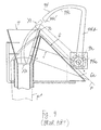
- a device herein referred to as a poker is sometimes utilized to forcibly push down the articles stuck in the chute. As shown in Fig.
- such a poker may be placed above and at the back of the former 6, comprising a generally L-shaped arm member 94 having a first part 94b extending upward from its base part 94a when it is at its initial position (shown by solid lines in Fig. 9) and a second part 94c extending forward from the upper end of the first part 94b.
- a driving means 92 such as a motor is provided for causing this arm member 94 to undergo a reciprocating rotary motion such that, as the arm member 94 is rotated in the forward direction from its initial position, the tip 94c' of the second part 94c will enter the interior of the chute 7 as shown by dotted line in Fig. 9, thereby reliably causing any articles stuck therein to drop into the bag which is being formed below.
- the arm member 94 is made of a synthetic resin material, however, forces inside tend be concentrated at its bend between the first and second parts 94b and 94c, deforming the arm member 94 as it swings back and forth many times periodically, and this makes it difficult for the tip 94c' to reliably come to the bottom center of the chute 7. If the arm member 94 becomes significantly deformed, its tip 94c' may strike the inner surface of the chute 7 and it may even break due to the material fatigue.
- the arm member 94 is made of a metallic material, on the other hand, it will be too heavy and the load on its driving means 92 becomes undesirably large. If the articles to be packaged are a food material, furthermore, a metal detector is sometimes provided for detecting any metallic substance which may be mixed in, but the use of such a metal detector will not be possible if the poker comprises a metallic arm member.
- Synthetic resin materials containing reinforcing fibers are both light and strong but the reinforcing fiber materials are easily peeled off and there arises a problem of hygiene if the articles to be packaged are a food material.
- the poker is generally positioned behind the former 6 and the chute 7, disposed such that the arm member 94, initially standing straight upward above and behind the former 6, rotates forward to send its second part 94c into the interior of the chute 7.
- the tip 94c' of the second part 94c should pass near the back edge part 7c of the upper opening of the chute 7 as indicated by dotted line X1 and enter the interior of the chute 7, and further that the tip 94c' should reach the bottom center of the conical part of the chute 7 as shown by dotted line X2.
- a poker for a packaging machine is defined in appended claim 1 and comprises a driver link, a generally L-shaped arm member, a connecting mechanism and a driving means for moving the driver link and thereby moving the arm member through the connecting mechanism.
- the arm member has a base part, an elongated first part extending upward when the arm member is at its initial position, and an elongated second part extending forward from the top end of the first part.
- the driver links is adapted to undergo a (first) reciprocating rotary motion around an axis which is stationary with respect to the packaging machine.
- a free-moving end part of the driver link distal from this stationary axis is rotatably connected to the base part of the arm member such that the arm member can undergo a (second) reciprocating rotary motion with respect to the driver link around a mobile axis which moves around the stationary axis with the rotary motion of the driver link.
- the connecting mechanism is for coordinating the aforementioned two (first and second) reciprocating rotary motions such that the tip of the arm member distal from its base part can move along a specified trajectory into the interior of the chute and reach a desired bottom center position inside the chute.
- this connecting mechanism comprises a cam follower and a stationary cam plate with an arcuate elongated opening such that this cam follower is constrained to move along the arcuate path defined by this opening, thereby coordinating the (first) rotary motion of the driver link around the stationary axis and the (second) rotary motion of the arm member around the mobile axis with moves with the driver link.
- the L-shaped arm member does not undergo a simple circular motion around a fixed center but the tip of the arm member undergoes a combination of two circular motions, one by the circular motion of the driver link and the other by the rotation of the arm member around a guiding center which itself undergoes a rotary motion.
- This invention also provides a packaging machine as defined in claim 8, preferably, with a generally L-shaped poker made of a synthetic resin material with an added strength where it bends.
- a synthetic resin poker embodying this invention may be characterized not only as being flat as a whole and comprised of a base part around which the poker undergoes a reciprocating rotary motion, a first part extending from the base part upward and a second part which bends forward from the first part and is intended to reach into the chute when the poker as a whole is rotated forward, but also wherein its bending section between its first and second parts comprises two tubular parts and a wall part connecting them so as to be cross-sectionally I-shaped.
- the cross-sectional shape of the tip portion of the second part is such that no indentations will be formed on the outer surface.
- Such a poker might be produced by a blow molding method.
- a poker thus formed is light in weight but rigid because of its cross-sectional shape at its bend between the first and second parts. Since the tip portion is shaped so as not to form indentations, fragments of the articles being pushed down will not easily get stuck, or become piled up, thereon. Still another advantage of this invention is that such an effective poker can be produced by an inexpensive method.
- FIG. 1 shows a packaging machine 1 embodying this invention, having a box-like main frame 2 with a bracket 3 for a film roll 14 at its back.
- a plurality of rollers 5 for guiding an elongated film F pulled out of the film roll 14 are supported by a frame structure 4 extending forward from the bracket 3.
- a former 6 for folding the film F such that its side edges will overlap is at the front part of the main frame 2 and a chute 7 is disposed so as to vertically penetrate the former 6.
- the former 6 has a film guide 6a extending backward like a skirt and a film folding part 6b for folding the forwardly guided film F along the film guide 6a such that its side edges are overlapped.
- the chute 7 includes a conical part 7a with a wide upper opening, through which articles dropped from a supply mechanism 15 are received, and a cylindrical part 7b which extends downward therefrom.
- a pair of film transporting mechanisms 8 (only one shown) for sending the folded film F downward is at both sides of the cylindrical part 7b of the chute 7, and a longitudinal sealer 9 for sealing the mutually overlapped side edges of the film F to shape it into a tubular form F' is on the front side of the cylindrical part 7b.
- transverse sealer 10 for sandwiching the tabular form F' from the front and back to transversely seal it over a seal area to thereby close the top edge part of a bag containing articles and to also form the bottom edge part of the next bag to be filled and cutting it across the seal area to separate the article-containing bag.
- the packaging machine 1 is provided with a device, herein referred to as the poker 20, for removing a clogged condition in the chute 7.
- a device herein referred to as the poker 20, for removing a clogged condition in the chute 7.
- the poker 20 is set on a support table 12 above the film guide 6a extending backward behind the former 6. As shown in Figs.
- the poker 20 comprises a rotary cylinder 22 set on a base member 21, a driver link 23 attached to the drive shaft 22a of this rotary cylinder 22 (serving as a stationary first axis of rotation), an arm member 24 driven by this driver link 23 and a cam plate 26 which is affixed to a vertical surface 21a of the base member 21 by means of bolts 25 and serves to cause the arm member 24 to move along a specified trajectory.
- the arm member 24 comprises a first part 24b which extends upward from its base part 24a when it is at its initial position (shown by solid lines in Fig.
- the arm member 24 has an extended part 24d which extends backward from the base part 24a transversely to the first part 24b.
- the moving end part, or the tip, of the driver link 23 is rotatably connected to the base part 24a of the arm member 24 around a pin 27 (serving as a mobile second axis of rotation), and a roller 28 is attached to the back end of the extended part 24d of the arm member 24 near the base part 24a (in the sense that the distance between the base part 24a and the roller 28 is much shorter than the length of the first part 24b).
- This roller 28 engages an elongated arcuate guide opening 26a formed through the cam plate 26.
- the base part 24a of the arm member 24 is constrained to move on a curved path on which the tip (the moving end) of the driver link 23 moves and the rear end of the extended part 24d is constrained to move along the arcuate guide opening 26a formed in the cam plate 26, thereby causing the arm member 24 as a whole to move along a specified trajectory.
- the arm member 24 moves from its initial uprightly standing position shown by solid lines in Fig.
- the cam plate 26 is further provided with stoppers 29 and 30 for contacting the arm member 24 so as to limit its motion within the range between the initial standing-up position and the final position where the tip part 24c' of its second part 24c reaches the bottom center part inside the chute 7 as shown by line X2.
- the elongated film F pulled out of the roll 14 supported by the bracket 3 is transported to the front of the main frame 2 by being guided by the guide rollers 5 and supplied from the most forwardly positioned of these rollers 5 (indicated by 5') to the film guide 6a extending backward from the former 6.
- the film transporting mechanisms 8 serve to keep pulling the film F downward around the cylindrical part 7b of the chute 7 and the longitudinal sealer 9 seals the mutually overlapped edge parts of the film F to produce a tubular form F'.
- the transverse sealer 10 disposed below the chute 7 seals the tubular film F' transversely and when the bottom edge of the bag being formed is thus sealed, articles supplied from the supply mechanism 15 pass through the chute 7 and drop into the bag being formed.
- the tubular film F' is thereafter cut transversely across a seal area and the filled bag below the seal area is dropped downward while the bag being formed above the seal area prepares itself to receive the next batch of articles to be dropped from above.
- the arm member 24 In making this reciprocating angular motion, the arm member 24 according to this invention follows a specified trajectory such that the tip 24c' of its second part 24c passes near the back edge portion 7c of the top opening of the chute 7 and reaches the bottom center part of the chute 7 after entering the interior of the chute 7 to make certain that a clogged condition of the chute 7 can be eliminated dependably.
- the trajectory of the arm member 24 is determined not only by the shape of the arm member 24 itself and by the trajectory of the moving end part of the driver link 23 but also by the shape of the guide opening 26a in the cam plate 26, the arm member 24 need not be large and still the interference can be avoided between the motion of the arm member 24 and that of the film F on the film guide 6a of the former 6 even if the former 6 is of a kind having a large film guide 6a.
- an optimum trajectory for the arm member 24 can be designed for a former of any given shape by selecting the length of the driver link 23 and the shape and the position of the guide opening 26a.
- Fig. 5 shows another poker 120 according to a second embodiment of this invention, which may be used for a packaging machine having a former 6 and a chute 7 which are identical to those shown in Figs. 1 and 2.
- a former 6 and a chute 7 which are identical to those shown in Figs. 1 and 2.
- like components shown in Fig. 5 are indicated by the same numerals as in Fig. 1 and may not be repetitiously explained what they are.
- the poker 120 shown in Fig. 5 also comprises a rotary cylinder 122 affixed to a base member 121, a driver link 123 attached to the drive shaft 122a of this rotary cylinder 122 and an arm member 124 driven by the driver link 123.
- this arm member 124 shown in Fig. 5 also has a first part 124b which extends upward from its base part 124a when it is at its initial position and an arcuate second part 124c which bends perpendicularly from the tip of the first part 121b and extends forward such that the arm member 124 as a whole is approximately L-shaped.
- a guide link 125 with one end rotatably attached to the base member 121 and the other end rotatably connected to the rear end of the extended part 124d near the base part 124a (in the sense that the distance between the base part 124a and the point at which the guide link 125 is connected to the extended part 124d is much shorter than the length of the first part 124b.)
- the overall trajectory of the arm member 124 of this poker 120 is determined by the circular motion ("the first rotary motion") of the moving end of the driver link 123 and the circular motion ("the second rotary motion") of the arm member 124, the two rotary motions (that is, the first and the second) being coordinated by the guide link.
- the overall trajectory can be optimally selected such that the tip 124c' of the second part 124c of the arm member 124 will pass near the back edge portion 7c of the upper opening of the conical part 7a of the chute 7 as the arm member 124 swings forward and will reach the bottom center part in the interior of the chute 7.
- Figs. 6, 7 and 8 show the cross-sectional shape of different parts of the arm member 124.
- the bending part of the L-shaped arm member 124 between its first part 124b and second part 124c is cross-sectionally shaped as shown in Fig. 6 in the form of letter I with two tubular parts along the inner and outer peripheries of this bending part and a wall part which connects these two tubular parts.
- the arm member 124 is hollow and cross-sectionally in the shape of an elongated circle as shown in Figs. 7 and 8 such that indentations will not form on its surface. This serves to prevent pieces of the articles being dropped from getting stuck to or becoming piled up on the outer surface of the arm member 124..
- the arm member 124 With the bending part thus formed, the arm member 124 is rigid and strong although it is made of synthetic resin and hence is light. When this arm member 124 undergoes a periodic reciprocating motion forward and backward, the force of inertia works forward when the arm member 124 swings forward and backward when the arm member 124 moves backward. Thus, although forces concentrate at the bending part, it does not bend as much and the arm member 124 does not fail to reach the bottom center of the chute 7 and does not break down by the material fatigue.
- the poker 124 according to this embodiment may be formed inexpensively by a blow molding method, providing a hollow interior to improve its rigidity and reducing the weight of the product.
Landscapes
- Engineering & Computer Science (AREA)
- Mechanical Engineering (AREA)
- Containers And Plastic Fillers For Packaging (AREA)
Claims (8)
- Finger (20) für eine Verpackungsmaschine, wobei die Verpackungsmaschine folgendes umfaßt: eine Schablone (6) mit einer Folienführung (6a), die sich rückwärts erstreckt und dem Falten einer Folie dient, die geführt ist zu der Schablone über die Folienführung, um beide Seitenkanten der Folie zu überlappen und zum Erzeugen einer rohrförmigen Gestalt, Versieglungseinrichtungen (9, 10) zum Versiegeln oder Verschweißen von Teilen der rohrförmigen Gestalt, um einen Beutel zu erzeugen, und einen Schacht (7), der an der Schablone angebracht ist zum Führen von Erzeugnissen, die in den Beutel hineinfallen, wobei der Finger folgendes aufweist:ein Antriebsglied (23), das geeignet ist zum Vollziehen einer ersten hin- und hergehenden Drehbewegung um eine erste Achse (22a) herum, die geeignet ist, um stationär zu sein bezüglich der Verpackungsmaschine;ein Armelement (24) mit einem Basisteil (24a), wobei sich ein länglicher erster Teil (24b) aufwärts erstreckt zu einem oberen Ende des Basisteils, wenn das Armelement sich bei einer Anfangsposition befindet, und wobei sich ein länglicher zweiter Teil (24c) vorwärts erstreckt von dem oberen Ende des ersten Teils, wobei das Armelement geeignet ist, eine zweite hin- und hergehende Drehbewegung zu vollziehen um eine mobile zweite Achse (27) herum, um die ein beweglicher Endteil des Antriebsglieds fern von der stationären ersten Achse drehbar verbunden ist an dem Basiselement des Armelements;einen Verbindungsmechanismus (26, 28) für die Koordination der ersten Drehbewegung des Antriebsglieds (23) um die stationäre erste Achse (22a) herum mit der zweiten Drehbewegung des Armelements (24) um die mobile zweite Achse (27) herum, um zu veranlassen, daß sich das Armelement vorwärts bewegt von der Anfangsposition entlang einer spezifischen Bahn; undeine Antriebseinrichtung (22) zum Veranlassen, daß das Antriebsglied eine erste hin- und hergehende Drehbewegung vollzieht und dadurch veranlaßt, daß das Armelement die zweite hin- und hergehende Drehbewegung vollzieht durch den Verbindungsmechanismus, so daß bei der Verwendung das freie Ende des Armelements (24) sich entlang einer spezifischen Bahn in das Innere des Schachts (7) hineinbewegt.
- Finger nach Anspruch 1, wobei der Verbindungsmechanismus ein Nockenmitnehmerelement (28) umfaßt, das an dem Armelement (24) nahe dem Basisteil befestigt ist, und eine Nockeneinrichtung (26) zum Bewegen des Nockenmitnehmerelements entlang einem spezifischen bogenförmigen Pfad.
- Finger nach Anspruch 2, wobei die Nockeneinrichtung eine stationäre Nockenplatte (26) mit einer Führungsöffnung (26a) aufweist, die sich entlang dem bogenförmigen Pfad erstreckt.
- Finger nach Anspruch 2 oder 3, wobei sich das Nockenmitnehmerlement (28) bei einer Position fern von dem Basisteil befindet in einer Richtung quer zu dem ersten Teil um einen Abstand, der viel kürzer ist als der erste Teil.
- Finger nach Anspruch 1, wobei das Armelement (124) eine Führungsmitte hat, die nahe dem Basisteil daran definiert ist, und wobei der Verbindungsmechanismus ein längliches Führungsglied (125) aufweist, das drehbar gestützt ist an einem Ende um eine andere stationäre Achse herum, und wobei das andere Ende drehbar verbunden ist mit dem Armelement bei der Führungsmitte, wodurch die Führungsmitte an dem Armelement begrenzt ist, um sich entlang einem bogenförmigen Pfad um die andere stationäre Achse herum zu bewegen.
- Finger nach Anspruch 5, wobei die Führungsmitte bei einer Position fern von dem Basisteil in einer Richtung definiert ist quer zu dem ersten Teil um einen Abstand, der viel kürzer ist als der erste Teil.
- Finger nach einem der vorangegangenen Ansprüche, wobei der zweite Teil (24c, 124c) eine Spitze fern von dem ersten Teil hat, wobei die Bahn derart spezifiziert ist, daß die Spitze eine spezifische Erzeugnisdurchtrittposition innerhalb dem Schacht erreicht.
- Verpackungsmaschine mit:einer Folientransporteinrichtung zum Transportieren einer länglichen Folie längs entlang eines spezifischen Folienpfads;einer Schablone (6) mit einer Folienführung (6a), die sich davon rückwärts erstreckt und auf dem Folienpfad angeordnet ist zum Falten der Folie, die über die Folienführung daran geführt ist, so daß sich entgegengesetzte Seitenkanten der Folie gegenseitig überlappen;einem Längsversiegler (9) zum Versiegeln oder Verschweißen der überschneidenden Seitenkanten in der Längsrichtung, um die Folie zu einer rohrförmigen Form auszubilden;einem Querversiegler (10) zum Versiegeln oder Verschweißen in der Querrichtung der rohrförmigen Folie quer zu der Richtung des Folienpfads, um einen Beutel zu erzeugen;einem Schacht (7), der an der Schablone (6) angebracht ist, um zu ermöglichen, daß Erzeugnisse durch diesen hindurch in den Beutel hineinfallen, wobei der Schacht eine obere Öffnung mit einer rückwärtigen Kante hat; undeinem Finger gemäß einem der vorangegangenen Ansprüche.1
Applications Claiming Priority (3)
| Application Number | Priority Date | Filing Date | Title |
|---|---|---|---|
| JP6237797 | 1997-02-28 | ||
| JP06237797A JP3746583B2 (ja) | 1997-02-28 | 1997-02-28 | 製袋包装機 |
| JP62377/97 | 1997-02-28 |
Publications (2)
| Publication Number | Publication Date |
|---|---|
| EP0861785A1 EP0861785A1 (de) | 1998-09-02 |
| EP0861785B1 true EP0861785B1 (de) | 2000-07-19 |
Family
ID=13198375
Family Applications (1)
| Application Number | Title | Priority Date | Filing Date |
|---|---|---|---|
| EP98300654A Expired - Lifetime EP0861785B1 (de) | 1997-02-28 | 1998-01-29 | Finger zum Freimachen des verstopften Füllrohrs einer Verpackungsmaschine |
Country Status (4)
| Country | Link |
|---|---|
| US (1) | US5983610A (de) |
| EP (1) | EP0861785B1 (de) |
| JP (1) | JP3746583B2 (de) |
| DE (1) | DE69800216T2 (de) |
Families Citing this family (7)
| Publication number | Priority date | Publication date | Assignee | Title |
|---|---|---|---|---|
| JP4094166B2 (ja) | 1999-04-07 | 2008-06-04 | 株式会社イシダ | 包装システム |
| US7003929B2 (en) * | 2003-07-25 | 2006-02-28 | Kraft Foods Holdings, Inc. | Apparatus and method for automated forming of sleeves for sliced products |
| US7523597B2 (en) * | 2007-03-20 | 2009-04-28 | J & F Business, Inc. | Apparatus and method for mounting a bag former |
| AU2012201494B2 (en) * | 2011-03-17 | 2016-12-01 | Tna Australia Pty Limited | A packaging machine former |
| ES1081704Y (es) * | 2013-03-21 | 2013-09-16 | J J Forwarder S L | Dispositivo rompedor de grumos para descarga fluida de granulados en envases de contenedores. |
| JP2015024849A (ja) * | 2013-07-26 | 2015-02-05 | 株式会社川島製作所 | 角型製袋充填筒用ホッパー |
| CN108792076B (zh) * | 2018-04-28 | 2020-04-28 | 重庆市纭凡食品开发有限责任公司 | 食品包装装置 |
Family Cites Families (5)
| Publication number | Priority date | Publication date | Assignee | Title |
|---|---|---|---|---|
| US3696179A (en) * | 1970-10-15 | 1972-10-03 | William A Jacobs | Extruding and filling containers made of foamed thermoplastic polymer |
| CH630018A5 (en) * | 1978-05-22 | 1982-05-28 | Gen Packaging Equip Co | Process and apparatus for the automatic filling of bags with particulate materials |
| CH667246A5 (de) * | 1985-02-18 | 1988-09-30 | Ilapak Res & Dev Sa | Vertikale schlauchbeutelmaschine. |
| US5199245A (en) * | 1991-10-01 | 1993-04-06 | Leo Daddario | Method and apparatus for packaging cloth articles |
| JP3091122B2 (ja) * | 1995-09-04 | 2000-09-25 | ハウス食品株式会社 | 固形物充填装置及びそれを用いた固形物充填方法 |
-
1997
- 1997-02-28 JP JP06237797A patent/JP3746583B2/ja not_active Expired - Fee Related
-
1998
- 1998-01-13 US US09/006,599 patent/US5983610A/en not_active Expired - Fee Related
- 1998-01-29 DE DE69800216T patent/DE69800216T2/de not_active Expired - Fee Related
- 1998-01-29 EP EP98300654A patent/EP0861785B1/de not_active Expired - Lifetime
Also Published As
| Publication number | Publication date |
|---|---|
| DE69800216T2 (de) | 2001-02-22 |
| JP3746583B2 (ja) | 2006-02-15 |
| EP0861785A1 (de) | 1998-09-02 |
| US5983610A (en) | 1999-11-16 |
| DE69800216D1 (de) | 2000-08-24 |
| JPH10236408A (ja) | 1998-09-08 |
Similar Documents
| Publication | Publication Date | Title |
|---|---|---|
| US6438926B1 (en) | Method and apparatus for placing a product in a flexible recloseable container | |
| EP0396838B1 (de) | Verpackungsmaschine | |
| US7032774B2 (en) | Web burster/inserter | |
| JP5267828B2 (ja) | 充填包装機 | |
| WO1991007320A1 (en) | Form, fill, seal and separate packaging machine for reclosable containers | |
| EP1818264B1 (de) | Verfahren und Anlage zum Hochgeschwindigkeitsverpacken von Aufgussprodukt enthaltenden Filterbeuteln | |
| EP0620152A1 (de) | Vorrichtung zum Anbringen von Ausgiessern | |
| EP0405595B1 (de) | Vorrichtung für die kontinuierliche Herstellung von Netzbeuteln | |
| CN87104442A (zh) | 在用薄片材料制成的包装里包装各种产品的方法和使用该方法的设备和因而得到的包装 | |
| EP0761536A2 (de) | System und Verfahren zum Einfüllen von festen Gegenständen | |
| US5983610A (en) | Poker for packaging machine | |
| EP1719704B1 (de) | Verpackungsmaschine | |
| JPH0431206A (ja) | 包装方法およびその装置 | |
| EP0965521A1 (de) | Vorrichtung zum Verpacken von Schüttgütern oder Gruppen von Gegenständen in einem Schlauchbeutel | |
| JP2012020791A (ja) | 横シール装置 | |
| US6662524B2 (en) | Closure applicator with swinging arm anvil | |
| US4446676A (en) | Bag handling apparatus for a bag making machine | |
| RU5578U1 (ru) | Устройство для изготовления, наполнения продуктом и запечатывания пакетов из термопластичного материала | |
| JPH0237684Y2 (de) | ||
| IE940917L (en) | Packaging machine and method | |
| JP2009023674A (ja) | 横シール装置 |
Legal Events
| Date | Code | Title | Description |
|---|---|---|---|
| PUAI | Public reference made under article 153(3) epc to a published international application that has entered the european phase |
Free format text: ORIGINAL CODE: 0009012 |
|
| AK | Designated contracting states |
Kind code of ref document: A1 Designated state(s): DE FR GB IT |
|
| AX | Request for extension of the european patent |
Free format text: AL;LT;LV;MK;RO;SI |
|
| 17P | Request for examination filed |
Effective date: 19981201 |
|
| GRAG | Despatch of communication of intention to grant |
Free format text: ORIGINAL CODE: EPIDOS AGRA |
|
| 17Q | First examination report despatched |
Effective date: 19990323 |
|
| AKX | Designation fees paid |
Free format text: DE FR GB IT |
|
| RBV | Designated contracting states (corrected) |
Designated state(s): DE FR GB IT |
|
| GRAG | Despatch of communication of intention to grant |
Free format text: ORIGINAL CODE: EPIDOS AGRA |
|
| GRAH | Despatch of communication of intention to grant a patent |
Free format text: ORIGINAL CODE: EPIDOS IGRA |
|
| GRAH | Despatch of communication of intention to grant a patent |
Free format text: ORIGINAL CODE: EPIDOS IGRA |
|
| GRAA | (expected) grant |
Free format text: ORIGINAL CODE: 0009210 |
|
| AK | Designated contracting states |
Kind code of ref document: B1 Designated state(s): DE FR GB IT |
|
| REF | Corresponds to: |
Ref document number: 69800216 Country of ref document: DE Date of ref document: 20000824 |
|
| ET | Fr: translation filed | ||
| ITF | It: translation for a ep patent filed | ||
| PLBE | No opposition filed within time limit |
Free format text: ORIGINAL CODE: 0009261 |
|
| STAA | Information on the status of an ep patent application or granted ep patent |
Free format text: STATUS: NO OPPOSITION FILED WITHIN TIME LIMIT |
|
| 26N | No opposition filed | ||
| REG | Reference to a national code |
Ref country code: GB Ref legal event code: IF02 |
|
| PGFP | Annual fee paid to national office [announced via postgrant information from national office to epo] |
Ref country code: FR Payment date: 20040108 Year of fee payment: 7 |
|
| PGFP | Annual fee paid to national office [announced via postgrant information from national office to epo] |
Ref country code: GB Payment date: 20040128 Year of fee payment: 7 |
|
| PGFP | Annual fee paid to national office [announced via postgrant information from national office to epo] |
Ref country code: DE Payment date: 20040205 Year of fee payment: 7 |
|
| PG25 | Lapsed in a contracting state [announced via postgrant information from national office to epo] |
Ref country code: IT Free format text: LAPSE BECAUSE OF NON-PAYMENT OF DUE FEES Effective date: 20050129 Ref country code: GB Free format text: LAPSE BECAUSE OF NON-PAYMENT OF DUE FEES Effective date: 20050129 |
|
| PG25 | Lapsed in a contracting state [announced via postgrant information from national office to epo] |
Ref country code: DE Free format text: LAPSE BECAUSE OF NON-PAYMENT OF DUE FEES Effective date: 20050802 |
|
| GBPC | Gb: european patent ceased through non-payment of renewal fee |
Effective date: 20050129 |
|
| PG25 | Lapsed in a contracting state [announced via postgrant information from national office to epo] |
Ref country code: FR Free format text: LAPSE BECAUSE OF NON-PAYMENT OF DUE FEES Effective date: 20050930 |
|
| REG | Reference to a national code |
Ref country code: FR Ref legal event code: ST |