EP0862013A1 - Elastische Aufhängungsvorrichtung für ein Auspuffrohr - Google Patents
Elastische Aufhängungsvorrichtung für ein Auspuffrohr Download PDFInfo
- Publication number
- EP0862013A1 EP0862013A1 EP98400080A EP98400080A EP0862013A1 EP 0862013 A1 EP0862013 A1 EP 0862013A1 EP 98400080 A EP98400080 A EP 98400080A EP 98400080 A EP98400080 A EP 98400080A EP 0862013 A1 EP0862013 A1 EP 0862013A1
- Authority
- EP
- European Patent Office
- Prior art keywords
- bar
- mass
- elastic
- vibrations
- rubber
- Prior art date
- Legal status (The legal status is an assumption and is not a legal conclusion. Google has not performed a legal analysis and makes no representation as to the accuracy of the status listed.)
- Granted
Links
Images


Classifications
-
- F—MECHANICAL ENGINEERING; LIGHTING; HEATING; WEAPONS; BLASTING
- F01—MACHINES OR ENGINES IN GENERAL; ENGINE PLANTS IN GENERAL; STEAM ENGINES
- F01N—GAS-FLOW SILENCERS OR EXHAUST APPARATUS FOR MACHINES OR ENGINES IN GENERAL; GAS-FLOW SILENCERS OR EXHAUST APPARATUS FOR INTERNAL-COMBUSTION ENGINES
- F01N13/00—Exhaust or silencing apparatus characterised by constructional features
- F01N13/18—Construction facilitating manufacture, assembly, or disassembly
- F01N13/1805—Fixing exhaust manifolds, exhaust pipes or pipe sections to each other, to engine or to vehicle body
- F01N13/1811—Fixing exhaust manifolds, exhaust pipes or pipe sections to each other, to engine or to vehicle body with means permitting relative movement, e.g. compensation of thermal expansion or vibration
- F01N13/1822—Fixing exhaust manifolds, exhaust pipes or pipe sections to each other, to engine or to vehicle body with means permitting relative movement, e.g. compensation of thermal expansion or vibration for fixing exhaust pipes or devices to vehicle body
-
- B—PERFORMING OPERATIONS; TRANSPORTING
- B60—VEHICLES IN GENERAL
- B60K—ARRANGEMENT OR MOUNTING OF PROPULSION UNITS OR OF TRANSMISSIONS IN VEHICLES; ARRANGEMENT OR MOUNTING OF PLURAL DIVERSE PRIME-MOVERS IN VEHICLES; AUXILIARY DRIVES FOR VEHICLES; INSTRUMENTATION OR DASHBOARDS FOR VEHICLES; ARRANGEMENTS IN CONNECTION WITH COOLING, AIR INTAKE, GAS EXHAUST OR FUEL SUPPLY OF PROPULSION UNITS IN VEHICLES
- B60K13/00—Arrangement in connection with combustion air intake or gas exhaust of propulsion units
- B60K13/04—Arrangement in connection with combustion air intake or gas exhaust of propulsion units concerning exhaust
-
- F—MECHANICAL ENGINEERING; LIGHTING; HEATING; WEAPONS; BLASTING
- F16—ENGINEERING ELEMENTS AND UNITS; GENERAL MEASURES FOR PRODUCING AND MAINTAINING EFFECTIVE FUNCTIONING OF MACHINES OR INSTALLATIONS; THERMAL INSULATION IN GENERAL
- F16F—SPRINGS; SHOCK-ABSORBERS; MEANS FOR DAMPING VIBRATION
- F16F7/00—Vibration-dampers; Shock-absorbers
- F16F7/10—Vibration-dampers; Shock-absorbers using inertia effect
- F16F7/104—Vibration-dampers; Shock-absorbers using inertia effect the inertia member being resiliently mounted
-
- F—MECHANICAL ENGINEERING; LIGHTING; HEATING; WEAPONS; BLASTING
- F16—ENGINEERING ELEMENTS AND UNITS; GENERAL MEASURES FOR PRODUCING AND MAINTAINING EFFECTIVE FUNCTIONING OF MACHINES OR INSTALLATIONS; THERMAL INSULATION IN GENERAL
- F16L—PIPES; JOINTS OR FITTINGS FOR PIPES; SUPPORTS FOR PIPES, CABLES OR PROTECTIVE TUBING; MEANS FOR THERMAL INSULATION IN GENERAL
- F16L55/00—Devices or appurtenances for use in, or in connection with, pipes or pipe systems
- F16L55/02—Energy absorbers; Noise absorbers
- F16L55/033—Noise absorbers
- F16L55/035—Noise absorbers in the form of specially adapted hangers or supports
Definitions
- the present invention relates to a device for elastic suspension for vehicle exhaust manifold having an internal combustion engine, comprising a body elastic provided with hooking means on the one hand to the body of the vehicle, on the other hand to said tubing.
- FIG. 2 representing the diagram theoretical and figure 3 the diagram of the stiffness obtained K as a function of the frequency f of the vibrations exerted between the attachment means 1 and 2 of the elastic body 3 of the device, for example rubber.
- this device behaves like a spring R in parallel with a shock absorber C, the whole being mounted between the body 6 of a motor vehicle and its exhaust manifold 7.
- the disadvantage of this prior art is visible in Figure 3 and resides in the stiffening dynamic, the stiffness K increasing with the frequency f. he there is poor damping of the idle modes, and line hash, i.e. from the first excitation mode of the exhaust manifold, between approximately 8 and 15 Hz.
- the elastic body 3 "of the device comprises between its two lateral filter arms 4 a beating mass M connected to these arms by elastic sections 5 in rubber.
- this beating mass device M curve in dashes
- the response of this beating mass device M certainly has a stiffness trough around 150 Hz, but also exhibits a significant stiffness peak around 120 or 130 Hz, which again is detrimental to the good filtration of the device at these frequencies.
- the object of the invention is to perfect this type of device by eliminating this stiffness peak or by moving in higher frequencies, where it will only more annoying.
- a compliant device to the invention of the general type defined at the start, is characterized in that it has at least one crossbar bearing an anti-swing mass, the end of this bar which is opposite to said mass being included in a zone of said body subjected to vibrations and this bar being maintained at a location between said area and said mass, by a relatively fixed part of said body, forming a pivot.
- the principle of the invention therefore lies in the fact that the mass attached to the device - thanks to the function of lever of said crossbar - moves in direction reverse of the vibrational stresses exerted on the device, this phenomenon increasing at low frequencies.
- FIG. 9 the diagram is again shown at 6. vehicle body and at 7 the exhaust manifold.
- the suspension device comprising an elastic body assumed to have two parallel branches, can be represented by the placing in series of two springs R mounted in parallel on two shock absorbers C also mounted in series.
- a mass anti-swing M is fixed to the end of a rigid bar 8 the opposite end of which 9 is included in a central region of the body with two branches, subjected to vibrations (arrow F) emanating from the tubing 7.
- the bar 8 is maintained at a location between the mass M and its end 9, by a part forming a pivot 10, arbitrarily represented as fixed to the body 6 of the vehicle.
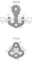
- a suspension device with a body of elongated rubber 11 in the general shape of an anchor for two branches 10. Holes 13 and 14 allow passage any hooking devices on the one hand at the cash register of a vehicle, on the other hand to its exhaust manifold (not shown in this figure).
- Two rigid bars 8, per example in rubber coated steel, are embedded by their ends 9 in the middle zone 16 of the body 11, subject to vibrations. These bars 8 cross the branches 10 forming pivots and carrying at each of their ends external an anti-swinging mass M making for example integral part of the corresponding bar 8 and capable of also be coated with rubber to prevent corrosion. It should be noted that the pivotal role of the branches 10 could be increased by stiffening these branches by a inner frame connecting them to each other.
Landscapes
- Engineering & Computer Science (AREA)
- General Engineering & Computer Science (AREA)
- Mechanical Engineering (AREA)
- Chemical & Material Sciences (AREA)
- Combustion & Propulsion (AREA)
- Transportation (AREA)
- Exhaust Silencers (AREA)
- Vibration Prevention Devices (AREA)
- Cooling, Air Intake And Gas Exhaust, And Fuel Tank Arrangements In Propulsion Units (AREA)
Applications Claiming Priority (2)
| Application Number | Priority Date | Filing Date | Title |
|---|---|---|---|
| FR9700474A FR2758602B1 (fr) | 1997-01-17 | 1997-01-17 | Dispositif de suspension elastique pour tubulure d'echappement |
| FR9700474 | 1997-01-17 |
Publications (2)
| Publication Number | Publication Date |
|---|---|
| EP0862013A1 true EP0862013A1 (de) | 1998-09-02 |
| EP0862013B1 EP0862013B1 (de) | 2002-03-27 |
Family
ID=9502705
Family Applications (1)
| Application Number | Title | Priority Date | Filing Date |
|---|---|---|---|
| EP98400080A Expired - Lifetime EP0862013B1 (de) | 1997-01-17 | 1998-01-16 | Elastische Aufhängungsvorrichtung für ein Auspuffrohr |
Country Status (5)
| Country | Link |
|---|---|
| US (1) | US6070849A (de) |
| EP (1) | EP0862013B1 (de) |
| DE (1) | DE69804364T2 (de) |
| ES (1) | ES2174397T3 (de) |
| FR (1) | FR2758602B1 (de) |
Cited By (1)
| Publication number | Priority date | Publication date | Assignee | Title |
|---|---|---|---|---|
| FR2829972A1 (fr) * | 2001-09-25 | 2003-03-28 | Renault | Ligne d'echappement de vehicule automobile, comportant un batteur inertiel |
Families Citing this family (16)
| Publication number | Priority date | Publication date | Assignee | Title |
|---|---|---|---|---|
| FR2805870B1 (fr) * | 2000-03-06 | 2002-06-14 | Hutchinson | Dispositif elastique de suspension d'une structure vibrante a une structure rigide |
| US8010800B2 (en) * | 2001-06-26 | 2011-08-30 | Sealedmedia Limited | Search engine and digital rights management |
| US6758300B2 (en) | 2002-02-20 | 2004-07-06 | The Pullman Company | Exhaust isolator system |
| JP2003269537A (ja) * | 2002-03-12 | 2003-09-25 | Toyo Tire & Rubber Co Ltd | 排気管用支持装置 |
| DE10257660B3 (de) * | 2002-12-10 | 2004-08-26 | Trelleborg Automotive Technical Centre Gmbh | Haltevorrichtung, insbesondere zum elastischen Aufhängen einer Abgasanlage eines Kraftfahrzeugs |
| US20040262460A1 (en) * | 2003-06-25 | 2004-12-30 | Pal Molnar | Elastomer hanger for an elastomer suspension |
| US7100738B1 (en) | 2003-08-13 | 2006-09-05 | Bellsouth Intellectual Property Corp. | Climbing device |
| US7140587B1 (en) * | 2003-08-14 | 2006-11-28 | Bellsouth Intellectual Property Corp. | Support device |
| FR2867537B1 (fr) * | 2004-03-12 | 2006-05-26 | Hutchinson | Dispositif de liaison antivibratoire |
| US7644911B2 (en) * | 2005-09-22 | 2010-01-12 | The Pullman Company | Isolator |
| US7510043B2 (en) * | 2006-08-29 | 2009-03-31 | The Pullman Company | Exhaust isolator |
| DE102010047275A1 (de) * | 2010-10-01 | 2012-04-05 | Emitec Gesellschaft Für Emissionstechnologie Mbh | Abgasanlage |
| US8608117B2 (en) | 2011-01-19 | 2013-12-17 | The Pullman Company | Isolator having push and turn mounting |
| US8366069B2 (en) | 2011-01-19 | 2013-02-05 | The Pullman Company | Isolator having socket mounting |
| JP2018179053A (ja) * | 2017-04-06 | 2018-11-15 | 東洋ゴム工業株式会社 | インシュレータ |
| US10576813B2 (en) | 2017-08-14 | 2020-03-03 | Ford Global Technologies, Llc | Mounting bracket for a vehicle component and method of forming |
Citations (4)
| Publication number | Priority date | Publication date | Assignee | Title |
|---|---|---|---|---|
| EP0531193A1 (de) * | 1991-09-02 | 1993-03-10 | Hutchinson | Elastische Abstützungsvorrichtung mit nicht-linearen elastischen Eigenschaften |
| US5398907A (en) * | 1992-06-12 | 1995-03-21 | Chemcast Corporation | Hanger for vehicle exhaust systems and the like |
| EP0710769A2 (de) * | 1994-11-07 | 1996-05-08 | WOCO Franz-Josef Wolf & Co. | Elastische Aufhängung |
| DE4439631A1 (de) * | 1994-11-07 | 1996-05-09 | Wolf Woco & Co Franz J | Elastische Aufhängung für eine Leitung, insbesondere die Abgasleitung der Brennkraftmaschine eines Kraftfahrzeuges |
Family Cites Families (10)
| Publication number | Priority date | Publication date | Assignee | Title |
|---|---|---|---|---|
| DE2823953C2 (de) * | 1978-06-01 | 1985-01-24 | Tünkers Maschinenbau GmbH, 4030 Ratingen | Aufhängevorrichtung für Rüttelbären an einem Lastaufnahmemittel |
| FR2503663A1 (fr) * | 1981-04-10 | 1982-10-15 | Aerospatiale | Dispositif de suspension antivibratoire pour helicoptere |
| US4415391A (en) * | 1982-04-06 | 1983-11-15 | Reid Glenn J | Reinforced molded rubber muffler hanger and method of making of same |
| US4634088A (en) * | 1985-03-01 | 1987-01-06 | General Motors Corporation | Suspension element for the exhaust system of a motor vehicle engine |
| JPS62151642A (ja) * | 1985-12-25 | 1987-07-06 | Bridgestone Corp | マフラ−用防振ゴム |
| US4817909A (en) * | 1987-12-07 | 1989-04-04 | Gencorp Inc. | Elastomeric hanger structure |
| US5433422A (en) * | 1988-09-02 | 1995-07-18 | Ross; Colin F. | Active vibration control through sensing and controlling forces on an intermediate body |
| FR2638799B1 (fr) * | 1988-11-09 | 1991-01-25 | Hutchinson | Support elastique a raideurs anisotropes, notamment pour la suspension de carrosseries |
| JP2585805B2 (ja) * | 1989-08-01 | 1997-02-26 | 東海ゴム工業 株式会社 | 排気系部材用支持装置 |
| US5829732A (en) * | 1996-03-27 | 1998-11-03 | Toyo Tire & Rubber Co., Ltd. | Exhaust pipe supporting device |
-
1997
- 1997-01-17 FR FR9700474A patent/FR2758602B1/fr not_active Expired - Fee Related
-
1998
- 1998-01-16 US US09/008,200 patent/US6070849A/en not_active Expired - Fee Related
- 1998-01-16 ES ES98400080T patent/ES2174397T3/es not_active Expired - Lifetime
- 1998-01-16 DE DE69804364T patent/DE69804364T2/de not_active Expired - Fee Related
- 1998-01-16 EP EP98400080A patent/EP0862013B1/de not_active Expired - Lifetime
Patent Citations (4)
| Publication number | Priority date | Publication date | Assignee | Title |
|---|---|---|---|---|
| EP0531193A1 (de) * | 1991-09-02 | 1993-03-10 | Hutchinson | Elastische Abstützungsvorrichtung mit nicht-linearen elastischen Eigenschaften |
| US5398907A (en) * | 1992-06-12 | 1995-03-21 | Chemcast Corporation | Hanger for vehicle exhaust systems and the like |
| EP0710769A2 (de) * | 1994-11-07 | 1996-05-08 | WOCO Franz-Josef Wolf & Co. | Elastische Aufhängung |
| DE4439631A1 (de) * | 1994-11-07 | 1996-05-09 | Wolf Woco & Co Franz J | Elastische Aufhängung für eine Leitung, insbesondere die Abgasleitung der Brennkraftmaschine eines Kraftfahrzeuges |
Cited By (2)
| Publication number | Priority date | Publication date | Assignee | Title |
|---|---|---|---|---|
| FR2829972A1 (fr) * | 2001-09-25 | 2003-03-28 | Renault | Ligne d'echappement de vehicule automobile, comportant un batteur inertiel |
| EP1297983A1 (de) * | 2001-09-25 | 2003-04-02 | Renault s.a.s. | Kraftfahrzeugabgasanlage mit Inertialklopfer |
Also Published As
| Publication number | Publication date |
|---|---|
| FR2758602A1 (fr) | 1998-07-24 |
| US6070849A (en) | 2000-06-06 |
| ES2174397T3 (es) | 2002-11-01 |
| FR2758602B1 (fr) | 1999-04-02 |
| DE69804364T2 (de) | 2002-11-28 |
| EP0862013B1 (de) | 2002-03-27 |
| DE69804364D1 (de) | 2002-05-02 |
Similar Documents
| Publication | Publication Date | Title |
|---|---|---|
| EP0862013B1 (de) | Elastische Aufhängungsvorrichtung für ein Auspuffrohr | |
| FR2559864A1 (fr) | Isolateur de vibrations | |
| FR2564413A1 (fr) | Suspension arriere pour motocyclette | |
| CA2956917C (fr) | Atterrisseur pour aeronef comportant un amortisseur principal et un amortisseur secondaire anti shimmy | |
| EP0223712B1 (de) | Änderungen an hydraulischen Dämpfern | |
| FR2481771A1 (fr) | Agencement de montage d'un moteur dans un vehicule | |
| FR2474974A1 (fr) | Structure de montage de moteur pour vehicule automobile | |
| EP0207958A1 (de) | Hydraulisches antischwingungslager. | |
| FR2755648A1 (fr) | Vehicule automobile comportant un bloc motopropulseur dote d'une suspension a debattement limite | |
| WO2022207989A1 (fr) | Dispositif pour limiter le debattement d'un amortisseur de vehicule notamment automobile | |
| EP1663689B1 (de) | Elastische stütze, insbesondere für abgassysteme an kraftfahrzeugen | |
| FR2655113A1 (fr) | Dispositif d'amortissement en elastomere rempli d'un fluide. | |
| FR2861337A1 (fr) | Dispositif de fixation d'un groupe motopropulseur a un chassis de vehicule au moyen d'une biellette. | |
| WO2007085712A1 (fr) | Poulie de vilebrequin | |
| FR3099218A1 (fr) | Unité d'amortissement des vibrations pour un véhicule à moteur hybride avec amortisseur à ressort et accouplement à friction ; ainsi que transmission | |
| FR3081954A1 (fr) | Dispositif de piege vibratoire de torsion | |
| FR3159661A1 (fr) | Barre de liaison pour le maintien d’un module de chauffage et/ou de climatisation dans un compartiment de véhicule automobile. | |
| FR3076500A1 (fr) | Systeme de suspension pour assise de siege automobile. | |
| FR3059748A1 (fr) | Amortisseur avec amortissement dynamique | |
| FR2892973A1 (fr) | Suspension de roue a amortissement selectif d'un vehicule automobile | |
| WO2025131788A1 (fr) | Dispositif de support d'un groupe motopropulseur de véhicule automobile | |
| FR3118111A1 (fr) | Systeme de suspension inertielle hydraulique dissymetrique | |
| FR2877158A1 (fr) | Alternateur comportant un dispositif d'amortissement des vibrations entre le stator d'excitatrice et le carter | |
| JPH06294432A (ja) | 車両用ショックアブソーバ | |
| FR3120818A1 (fr) | Dispositif de suspension inertielle hydraulique, methode, amortisseur et vehicule sur la base d’un tel dispositif |
Legal Events
| Date | Code | Title | Description |
|---|---|---|---|
| PUAI | Public reference made under article 153(3) epc to a published international application that has entered the european phase |
Free format text: ORIGINAL CODE: 0009012 |
|
| AK | Designated contracting states |
Kind code of ref document: A1 Designated state(s): DE ES GB IT |
|
| AX | Request for extension of the european patent |
Free format text: AL;LT;LV;MK;RO;SI |
|
| 17P | Request for examination filed |
Effective date: 19981016 |
|
| AKX | Designation fees paid |
Free format text: DE ES GB IT |
|
| RBV | Designated contracting states (corrected) |
Designated state(s): DE ES GB IT |
|
| GRAG | Despatch of communication of intention to grant |
Free format text: ORIGINAL CODE: EPIDOS AGRA |
|
| 17Q | First examination report despatched |
Effective date: 20010620 |
|
| GRAG | Despatch of communication of intention to grant |
Free format text: ORIGINAL CODE: EPIDOS AGRA |
|
| GRAH | Despatch of communication of intention to grant a patent |
Free format text: ORIGINAL CODE: EPIDOS IGRA |
|
| GRAH | Despatch of communication of intention to grant a patent |
Free format text: ORIGINAL CODE: EPIDOS IGRA |
|
| REG | Reference to a national code |
Ref country code: GB Ref legal event code: IF02 |
|
| GRAA | (expected) grant |
Free format text: ORIGINAL CODE: 0009210 |
|
| AK | Designated contracting states |
Kind code of ref document: B1 Designated state(s): DE ES GB IT |
|
| REF | Corresponds to: |
Ref document number: 69804364 Country of ref document: DE Date of ref document: 20020502 |
|
| REG | Reference to a national code |
Ref country code: ES Ref legal event code: FG2A Ref document number: 2174397 Country of ref document: ES Kind code of ref document: T3 |
|
| PLBE | No opposition filed within time limit |
Free format text: ORIGINAL CODE: 0009261 |
|
| STAA | Information on the status of an ep patent application or granted ep patent |
Free format text: STATUS: NO OPPOSITION FILED WITHIN TIME LIMIT |
|
| 26N | No opposition filed |
Effective date: 20021230 |
|
| PGFP | Annual fee paid to national office [announced via postgrant information from national office to epo] |
Ref country code: ES Payment date: 20040105 Year of fee payment: 7 |
|
| PGFP | Annual fee paid to national office [announced via postgrant information from national office to epo] |
Ref country code: DE Payment date: 20040109 Year of fee payment: 7 Ref country code: GB Payment date: 20040109 Year of fee payment: 7 |
|
| PG25 | Lapsed in a contracting state [announced via postgrant information from national office to epo] |
Ref country code: IT Free format text: LAPSE BECAUSE OF NON-PAYMENT OF DUE FEES;WARNING: LAPSES OF ITALIAN PATENTS WITH EFFECTIVE DATE BEFORE 2007 MAY HAVE OCCURRED AT ANY TIME BEFORE 2007. THE CORRECT EFFECTIVE DATE MAY BE DIFFERENT FROM THE ONE RECORDED. Effective date: 20050116 Ref country code: GB Free format text: LAPSE BECAUSE OF NON-PAYMENT OF DUE FEES Effective date: 20050116 |
|
| PG25 | Lapsed in a contracting state [announced via postgrant information from national office to epo] |
Ref country code: ES Free format text: LAPSE BECAUSE OF NON-PAYMENT OF DUE FEES Effective date: 20050117 |
|
| PG25 | Lapsed in a contracting state [announced via postgrant information from national office to epo] |
Ref country code: DE Free format text: LAPSE BECAUSE OF NON-PAYMENT OF DUE FEES Effective date: 20050802 |
|
| GBPC | Gb: european patent ceased through non-payment of renewal fee |
Effective date: 20050116 |
|
| REG | Reference to a national code |
Ref country code: ES Ref legal event code: FD2A Effective date: 20050117 |