EP0862025A2 - Radiateur à tubes - Google Patents
Radiateur à tubes Download PDFInfo
- Publication number
- EP0862025A2 EP0862025A2 EP98103348A EP98103348A EP0862025A2 EP 0862025 A2 EP0862025 A2 EP 0862025A2 EP 98103348 A EP98103348 A EP 98103348A EP 98103348 A EP98103348 A EP 98103348A EP 0862025 A2 EP0862025 A2 EP 0862025A2
- Authority
- EP
- European Patent Office
- Prior art keywords
- connection
- tube
- sealing corner
- connecting piece
- sealing
- Prior art date
- Legal status (The legal status is an assumption and is not a legal conclusion. Google has not performed a legal analysis and makes no representation as to the accuracy of the status listed.)
- Withdrawn
Links
- 239000000463 material Substances 0.000 claims abstract description 3
- 238000007789 sealing Methods 0.000 claims description 67
- 239000003566 sealing material Substances 0.000 claims description 2
- 238000010438 heat treatment Methods 0.000 abstract description 5
- 244000089486 Phragmites australis subsp australis Species 0.000 description 2
- 238000006073 displacement reaction Methods 0.000 description 1
- 239000013013 elastic material Substances 0.000 description 1
- 238000003780 insertion Methods 0.000 description 1
- 230000037431 insertion Effects 0.000 description 1
- 238000004519 manufacturing process Methods 0.000 description 1
- 229910000679 solder Inorganic materials 0.000 description 1
- 238000005476 soldering Methods 0.000 description 1
- 238000003466 welding Methods 0.000 description 1
Images



Classifications
-
- F—MECHANICAL ENGINEERING; LIGHTING; HEATING; WEAPONS; BLASTING
- F24—HEATING; RANGES; VENTILATING
- F24D—DOMESTIC- OR SPACE-HEATING SYSTEMS, e.g. CENTRAL HEATING SYSTEMS; DOMESTIC HOT-WATER SUPPLY SYSTEMS; ELEMENTS OR COMPONENTS THEREFOR
- F24D19/00—Details
- F24D19/0002—Means for connecting central heating radiators to circulation pipes
-
- F—MECHANICAL ENGINEERING; LIGHTING; HEATING; WEAPONS; BLASTING
- F24—HEATING; RANGES; VENTILATING
- F24D—DOMESTIC- OR SPACE-HEATING SYSTEMS, e.g. CENTRAL HEATING SYSTEMS; DOMESTIC HOT-WATER SUPPLY SYSTEMS; ELEMENTS OR COMPONENTS THEREFOR
- F24D19/00—Details
- F24D19/0002—Means for connecting central heating radiators to circulation pipes
- F24D19/0073—Means for changing the flow of the fluid inside a radiator
Definitions
- the invention relates to a tubular radiator consisting of a plurality of similar members arranged one next to the other and connected to one another on the hubs according to the preamble of the first claim.
- DE 43 08 336 A1 describes a multi-column heat body with vertically downward-facing connections for flow and return, the connections being able to be arranged on any radiator elements and a forced run from the flow in the form of a tube to the radiator element on which the valve is arranged is done.
- a similar connection, in which the connection between the pipe and the connecting piece is made via a liquid-tight plug connection or a screw connection directly into a lateral opening of the connecting piece, is shown in DE 296 10 869 U1.
- the connecting piece is welded into an opening in the hub.
- the decisive disadvantage of this solution is that it is difficult during assembly to position the mostly relatively long pipe in the side opening of the connecting piece.
- the invention has for its object to develop a tube radiator that ensures easy assembly of the connection elements.
- the tubular radiator consists, as is known, of a plurality of radiator elements of the same type which are arranged next to one another and which are connected to one another at the top and bottom, the connecting piece arranged on any radiator element being connected to a radiator element arranged at the end via a tube which projects through the hubs of the radiator elements located therebetween .
- the connection between the connecting piece and the tube is made via a material connection, a positive connection or a sealing corner.
- the sealing corner has two mutually perpendicular and interconnecting bores.
- the connecting piece and with the second horizontal bore the tube are connected in a liquid-tight manner, for example via a soldered or welded connection, a screw connection or a plug connection.
- the connecting piece protrudes into the first bore and the tube is pushed with one end over the outer contour of the sealing corner so that the second bore inevitably opens into the tube.
- this advantageously lies at one end against a corresponding stop on the sealing corner. At the same time, this stop results in a defined position fixation between the longitudinal axis of the tube and the axis of the first bore.
- the other end of the pipe pointing away from the sealing corner is designed so that it characterizes the position of the sealing corner and the angle of rotation about its longitudinal axis and thus enables a position determination of the first hole in the sealing corner, so that it can be determined during assembly whether the first hole of the Sealing corner points in the direction of the connector plug and is approximately aligned with the bore of the connector plug.
- the two ends of the tube preferably have bevels pointing in the same direction.
- connection plug arranged in a liquid-tight manner in a breakthrough does not reach the sealing corner and that the connection from the plug to the sealing corner takes place via a connecting bushing which projects into the first bore of the sealing corner and between its outer diameter and the inner diameter of the connecting piece is sealed in a liquid-tight manner.
- the connection socket is fastened, for example, via a plug connection, a clamp connection or a screw connection.
- the sealing corner is preferably made of an elastic sealing material corresponding to the ambient conditions.
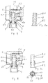
- the section of the lower hub area of a tube radiator is shown in FIG. 1.
- the individual structurally identical radiator elements 1.1, 1.2, 1.3 1.4 are connected to one another at their upper and lower hubs 2.1, 2.2, 2.3 and 2.4.
- the radiator element 1.4 can also connect further radiator elements up to 1.n with hubs up to 2n.
- the hubs 2.1, 2.2, 2.3 and 2.4 have contact surfaces A with overflow openings D.
- the radiator element 1.1 is arranged at the end.
- the overflow opening D facing outwards is provided with a sealing plug V.
- a seal 6 is provided between the first lower hub 1.1 and the second lower hub 2.2 to separate the forward and return flow.
- the connection piece 3 is arranged in the lower hub 2.4 of the fourth radiator element.
- a tube 4 is arranged between this hub 2.4 and the first lower hub 2.1, which leads through the overflow openings D.
- the tube 4 is chamfered at both ends at the same angle.
- the seal 6 also seals the outer diameter of the tube 4.
- the connection between the connecting piece 3 and the tube 4 is made via a sealing corner 5, which has two mutually perpendicular bores 5.1 and 5.2 and a stop 5.3 on the outer contour.
- the stop 5.3 is advantageously formed all around according to the slope of the tube 4.
- the pipe 4 lying perpendicular to the connecting piece 4 and extending through the hubs 2.1 to 2.4 is pushed over the outer contour of the sealing corner 5 up to its stop 5.3, so that the second bore 5.2 of the sealing corner 5 opens into the pipe 4.
- the design of the stop and the chamfering of the pipe ends make it possible to ensure that the bore 5.1 of the sealing corner 5 is precisely fixed in position.
- the bore 5.1 is always aligned with the connecting piece if the tube end in the hub 1.1 points downward with its longest point of the bevel.
- the sealing corner 5 has a phase 5.4 in the direction of the tube.
- the connecting piece 3 is also chamfered in the direction of the sealing corner 5 in order to facilitate insertion into the bore 5.1.
- the connecting piece 3 has an annular stop 3.1, up to which it is inserted into the hub 2.4.
- the connection piece 3 is preferably attached to the hub 2.4 by a welded connection.
- the sealing corner 5 consists in particular at the joining positions or entirely of a permanently elastic material which ensures a reliable and liquid-tight plug connection to the connecting piece 3 and to the pipe.
- FIG. 2 The sectional view of the connection according to the invention with a connecting socket 8 between sealing corner 5 and connecting piece 3 is shown in FIG. 2.
- the connecting bush 8 has an axial through bore 8.1.
- the connecting piece 3 is welded into the hub 2.4 and does not reach the sealing corner 5.
- the connecting bushing 8 is arranged, which rests on the inner edge of the stop 3.1 with an enlarged section 8.2 and engages with its end opposite the section 8.2 in the bore 5.1 of the sealing corner 5.
- the connecting socket 8 also has a phase to simplify assembly.
- a sealing ring 9 is arranged for liquid-tight sealing.
- the individual part drawing of the connecting socket 8 is shown in Fig. 2a.
- tube 4 and sealing corner 5 are first connected to one another and the connecting piece 3 is welded into the opening 7 of the hub 42.4. Subsequently, the tube 4 with the sealing corner 5 is inserted through the lower hubs 2.1 to 2.4 such that the bore 5.1 points in the direction of the connecting piece 3 and is flush with it. Subsequently, the connecting socket 8 is inserted through the connecting piece 3 into the bore 5.1 until its paragraph 8.2 rests against the inside of the stop 3.1 of the connecting piece 3. Appropriate dimensioning of the outer diameter of the connecting bush 8 and the inner diameter of the bore 5.1 of the sealing corner 5 ensures a reliable and liquid-tight connection. The same applies to the connection between the sealing corner 5 and the tube 4.
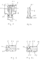
- resilient elements 10 can be provided in the radial direction on its outer diameter (see FIGS. 3, 3a, 3b), which when inserted behind the in snap the hub 2.4 projecting end edge of the connecting piece 3 and thus prevent the axial movement of the connecting bush 8.
- the front view and the top view of such a connecting bush 8 are shown in FIGS. 3a and 3b.
- the connecting bush 8 has on its outer diameter a plurality of resilient elements 10 distributed around the circumference, which can be compressed in the radial direction.
- Another embodiment variant consists in screwing the connecting socket 8 into the connecting piece 3 (FIGS. 4 and 4a).
- the connecting socket 8 has an external thread GA after the paragraph 8.2 and the connecting piece 3 is provided with an internal thread GI.
- the sealing corner 5 is shown in FIG. 5 and a sectional view of the sealing corner 5 in FIG. 5a.
- the sealing corner 5 is essentially cylindrical and has two basic bores 5.1 and 5.2 which are arranged at right angles to one another and open into one another.
- the bore 5.2 is eccentric and parallel to the axis of the sealing corner 5.
- the stop 5.3 for the tube 4 is provided on the outer diameter of the sealing corner 5.
- This stop 5.3 consists of a circumferential shoulder, which is inclined corresponding to the bevel in the axial direction.
- a phase 5.4 is provided in the direction of the tube 4.
- the sealing corner 5 also has a recess 11 in the form of a square or hexagon on the end face opposite this phase 5.4.
- FIG. 6 Another embodiment variant is branched in FIG. 6.
- the connection between sealing corner 5 and connecting piece 3 is made via a screw connection and between sealing corner 5 and pipe 4 via a plug connection.
- the connecting piece 3 leads over a tapered area to the sealing corner 5, is screwed into the latter and has a seal D2 between the sealing corner 5 and a shoulder facing the sealing corner 5.
- the tube 4 is pressed by the plug V when screwing into the threaded ring G in the direction of the sealing corner and has a shoulder 4.2, which is pressed against the seal D at the same time, so that a liquid-tight connection is made.
- the tube 4 does not reach over the sealing corner, but projects into a hole provided in the sealing corner 5, so that the connection to the hole 5.2 of the sealing corner 5 is made.
- a further seal D3 can be provided between tube 4 and sealing corner 5.
- a seal D3 for example, a liquid-tight solder connection between tube 4 and sealing corner 5 can also be provided.
- Bores 4.1 are also provided in the tube 4 in the area of the hub 2.1 of the first radiator element, through which holes the heating medium can enter the tube radiator.
- the tube can also be pressed against the seal D via an intermediate bushing with the stop 4.2. The intermediate bush is then between the stop 4.2 and the closure cover V.
- a pressure piece X can also be axially displaceably mounted on the tube 4 (FIG. 7). The intermediate bushing Z presses against this.
- seal D both to the tube 4 and to the adjoining radiator element (hub 2.2) is ensured.
- a seal D4 eg O-ring is also provided between pressure piece X and seal D.
- connection between sealing corner 5 and connecting piece 3 also via a integral connection e.g. by soldering or welding can be done.
Landscapes
- Engineering & Computer Science (AREA)
- Physics & Mathematics (AREA)
- Thermal Sciences (AREA)
- Chemical & Material Sciences (AREA)
- Combustion & Propulsion (AREA)
- Mechanical Engineering (AREA)
- General Engineering & Computer Science (AREA)
- Joints With Pressure Members (AREA)
- Branch Pipes, Bends, And The Like (AREA)
- Cooling, Air Intake And Gas Exhaust, And Fuel Tank Arrangements In Propulsion Units (AREA)
Applications Claiming Priority (2)
| Application Number | Priority Date | Filing Date | Title |
|---|---|---|---|
| DE19707935 | 1997-02-27 | ||
| DE1997107935 DE19707935C1 (de) | 1997-02-27 | 1997-02-27 | Anschluß für einen Röhrenradiator |
Publications (2)
| Publication Number | Publication Date |
|---|---|
| EP0862025A2 true EP0862025A2 (fr) | 1998-09-02 |
| EP0862025A3 EP0862025A3 (fr) | 2000-04-12 |
Family
ID=7821701
Family Applications (1)
| Application Number | Title | Priority Date | Filing Date |
|---|---|---|---|
| EP98103348A Withdrawn EP0862025A3 (fr) | 1997-02-27 | 1998-02-26 | Radiateur à tubes |
Country Status (2)
| Country | Link |
|---|---|
| EP (1) | EP0862025A3 (fr) |
| DE (1) | DE19707935C1 (fr) |
Cited By (4)
| Publication number | Priority date | Publication date | Assignee | Title |
|---|---|---|---|---|
| DE102004029705A1 (de) * | 2004-06-21 | 2006-01-12 | Kermi Gmbh | Heizkörper |
| WO2008003291A1 (fr) * | 2006-07-05 | 2008-01-10 | Kermi Gmbh | Élément chauffant, en particulier radiateur à tubes |
| DE202008006845U1 (de) | 2008-05-16 | 2008-07-24 | Kermi Gmbh | Heizkörper |
| DE202008007511U1 (de) | 2008-06-03 | 2008-08-14 | Kermi Gmbh | Heizkörper |
Citations (2)
| Publication number | Priority date | Publication date | Assignee | Title |
|---|---|---|---|---|
| DE4308336A1 (de) | 1993-03-16 | 1994-09-22 | Hkf Heizkoerperfertigung Meini | Mehrsäuliger Wärmekörper |
| DE29610869U1 (de) | 1996-06-21 | 1996-08-29 | Zehnder Verkaufs- und Verwaltungs AG, Gränichen | Heizkörper |
-
1997
- 1997-02-27 DE DE1997107935 patent/DE19707935C1/de not_active Expired - Fee Related
-
1998
- 1998-02-26 EP EP98103348A patent/EP0862025A3/fr not_active Withdrawn
Patent Citations (2)
| Publication number | Priority date | Publication date | Assignee | Title |
|---|---|---|---|---|
| DE4308336A1 (de) | 1993-03-16 | 1994-09-22 | Hkf Heizkoerperfertigung Meini | Mehrsäuliger Wärmekörper |
| DE29610869U1 (de) | 1996-06-21 | 1996-08-29 | Zehnder Verkaufs- und Verwaltungs AG, Gränichen | Heizkörper |
Cited By (4)
| Publication number | Priority date | Publication date | Assignee | Title |
|---|---|---|---|---|
| DE102004029705A1 (de) * | 2004-06-21 | 2006-01-12 | Kermi Gmbh | Heizkörper |
| WO2008003291A1 (fr) * | 2006-07-05 | 2008-01-10 | Kermi Gmbh | Élément chauffant, en particulier radiateur à tubes |
| DE202008006845U1 (de) | 2008-05-16 | 2008-07-24 | Kermi Gmbh | Heizkörper |
| DE202008007511U1 (de) | 2008-06-03 | 2008-08-14 | Kermi Gmbh | Heizkörper |
Also Published As
| Publication number | Publication date |
|---|---|
| DE19707935C1 (de) | 1998-12-17 |
| EP0862025A3 (fr) | 2000-04-12 |
Similar Documents
| Publication | Publication Date | Title |
|---|---|---|
| DE2121381C3 (de) | Zahnstangenlenkung für Kraftfahrzeuge | |
| DE1500800B1 (de) | Steckmutter aus Kunststoff | |
| DE10147141A1 (de) | Abgedichtete, verstellbare und selbsthemmende Schraubverbindung | |
| DE3447036A1 (de) | Formschluessige verbindung zwischen einem profilstab und einem knotenelement | |
| DE60205641T2 (de) | Zur verbindung zweier röhrenförmiger elemente verwendete kupplung und montageverfahren dafür | |
| DE102007031337B4 (de) | Motorsäge und Klemmelement | |
| DE3220945C2 (de) | Schweißstellenfreie Verbindung | |
| EP0862025A2 (fr) | Radiateur à tubes | |
| DE4325738A1 (de) | Ventilanordnung für die Armatur eines Kompaktheizkörpers | |
| DE69602925T2 (de) | Rohrkupplung und verfahren zum verbinden eines rohres an einem verbindungsstück | |
| DE2425121A1 (de) | Verbindungseinrichtung fuer leitungen | |
| DE1904479B2 (de) | Armaturteil | |
| DE2331752C2 (de) | Einrichtung zur druckdichten Durchführung eines Verbindungsrohres durch zwei miteinander verspannbare Bauteile | |
| EP3217056B1 (fr) | Robinet auto-perceur à soupape | |
| DE10106510B4 (de) | Aluminium-Wärmeübertrager | |
| DE10107465C1 (de) | Steckverbindung für Rohrleitungen | |
| EP1956251A1 (fr) | Raccord d'angle amovible pour tubes, element d'angle destine au raccord d'angle amovible pour tubes et douille d'ecartement destinee au raccord d'angle amovible pour tubes | |
| EP1443276B1 (fr) | Raccordement de radiateur | |
| EP3217055B1 (fr) | Robinet auto-perceur à soupape | |
| DE10233115B4 (de) | Röhrenradiator | |
| DE19734393C2 (de) | Heizkörper, insbesondere Röhrenradiator | |
| DE102022210889A1 (de) | Sensoreinrichtung | |
| DE3512577C2 (fr) | ||
| DE19753100C1 (de) | Montageschelle | |
| AT517099B1 (de) | Vorrichtung zur Befestigung einer Abdeckhaube an einem Gehäuse |
Legal Events
| Date | Code | Title | Description |
|---|---|---|---|
| PUAI | Public reference made under article 153(3) epc to a published international application that has entered the european phase |
Free format text: ORIGINAL CODE: 0009012 |
|
| 17P | Request for examination filed |
Effective date: 19980226 |
|
| AK | Designated contracting states |
Kind code of ref document: A2 Designated state(s): AT BE CH DE DK ES FI FR GB GR IE IT LI LU MC NL PT |
|
| AX | Request for extension of the european patent |
Free format text: AL;LT;LV;MK;RO;SI |
|
| PUAL | Search report despatched |
Free format text: ORIGINAL CODE: 0009013 |
|
| AK | Designated contracting states |
Kind code of ref document: A3 Designated state(s): AT BE CH DE DK ES FI FR GB GR IE IT LI LU MC NL PT |
|
| AX | Request for extension of the european patent |
Free format text: AL;LT;LV;MK;RO;SI |
|
| STAA | Information on the status of an ep patent application or granted ep patent |
Free format text: STATUS: THE APPLICATION HAS BEEN WITHDRAWN |
|
| 18W | Application withdrawn |
Withdrawal date: 20000729 |