EP0862033A1 - Einrichtung zur Ersetzung einer Bandträgerrolle in einem Wärmebehandlungsofen - Google Patents
Einrichtung zur Ersetzung einer Bandträgerrolle in einem Wärmebehandlungsofen Download PDFInfo
- Publication number
- EP0862033A1 EP0862033A1 EP98400333A EP98400333A EP0862033A1 EP 0862033 A1 EP0862033 A1 EP 0862033A1 EP 98400333 A EP98400333 A EP 98400333A EP 98400333 A EP98400333 A EP 98400333A EP 0862033 A1 EP0862033 A1 EP 0862033A1
- Authority
- EP
- European Patent Office
- Prior art keywords
- roller
- flanges
- support
- roll
- oven
- Prior art date
- Legal status (The legal status is an assumption and is not a legal conclusion. Google has not performed a legal analysis and makes no representation as to the accuracy of the status listed.)
- Granted
Links
- 238000010438 heat treatment Methods 0.000 title claims description 5
- 230000001360 synchronised effect Effects 0.000 claims abstract description 7
- 238000006073 displacement reaction Methods 0.000 claims abstract description 6
- 238000007789 sealing Methods 0.000 claims abstract description 6
- 239000000872 buffer Substances 0.000 claims description 12
- 238000001816 cooling Methods 0.000 claims description 11
- XLYOFNOQVPJJNP-UHFFFAOYSA-N water Substances O XLYOFNOQVPJJNP-UHFFFAOYSA-N 0.000 claims description 5
- 229910000831 Steel Inorganic materials 0.000 claims description 3
- 239000000919 ceramic Substances 0.000 claims description 3
- 239000000835 fiber Substances 0.000 claims description 3
- 238000000034 method Methods 0.000 claims description 3
- 239000010959 steel Substances 0.000 claims description 3
- 238000009434 installation Methods 0.000 claims description 2
- 230000008569 process Effects 0.000 claims description 2
- 239000011819 refractory material Substances 0.000 claims description 2
- 238000005096 rolling process Methods 0.000 claims description 2
- 230000008859 change Effects 0.000 abstract description 2
- 230000000694 effects Effects 0.000 abstract 1
- 230000009471 action Effects 0.000 description 1
- 230000005540 biological transmission Effects 0.000 description 1
- 230000015556 catabolic process Effects 0.000 description 1
- 238000006731 degradation reaction Methods 0.000 description 1
- 238000004519 manufacturing process Methods 0.000 description 1
- 239000000463 material Substances 0.000 description 1
Images
Classifications
-
- F—MECHANICAL ENGINEERING; LIGHTING; HEATING; WEAPONS; BLASTING
- F27—FURNACES; KILNS; OVENS; RETORTS
- F27B—FURNACES, KILNS, OVENS OR RETORTS IN GENERAL; OPEN SINTERING OR LIKE APPARATUS
- F27B9/00—Furnaces through which the charge is moved mechanically, e.g. of tunnel type; Similar furnaces in which the charge moves by gravity
- F27B9/14—Furnaces through which the charge is moved mechanically, e.g. of tunnel type; Similar furnaces in which the charge moves by gravity characterised by the path of the charge during treatment; characterised by the means by which the charge is moved during treatment
- F27B9/20—Furnaces through which the charge is moved mechanically, e.g. of tunnel type; Similar furnaces in which the charge moves by gravity characterised by the path of the charge during treatment; characterised by the means by which the charge is moved during treatment the charge moving in a substantially straight path
- F27B9/24—Furnaces through which the charge is moved mechanically, e.g. of tunnel type; Similar furnaces in which the charge moves by gravity characterised by the path of the charge during treatment; characterised by the means by which the charge is moved during treatment the charge moving in a substantially straight path being carried by a conveyor
- F27B9/2407—Furnaces through which the charge is moved mechanically, e.g. of tunnel type; Similar furnaces in which the charge moves by gravity characterised by the path of the charge during treatment; characterised by the means by which the charge is moved during treatment the charge moving in a substantially straight path being carried by a conveyor the conveyor being constituted by rollers (roller hearth furnace)
-
- C—CHEMISTRY; METALLURGY
- C21—METALLURGY OF IRON
- C21D—MODIFYING THE PHYSICAL STRUCTURE OF FERROUS METALS; GENERAL DEVICES FOR HEAT TREATMENT OF FERROUS OR NON-FERROUS METALS OR ALLOYS; MAKING METAL MALLEABLE, e.g. BY DECARBURISATION OR TEMPERING
- C21D9/00—Heat treatment, e.g. annealing, hardening, quenching or tempering, adapted for particular articles; Furnaces therefor
- C21D9/52—Heat treatment, e.g. annealing, hardening, quenching or tempering, adapted for particular articles; Furnaces therefor for wires; for strips ; for rods of unlimited length
- C21D9/54—Furnaces for treating strips or wire
- C21D9/56—Continuous furnaces for strip or wire
- C21D9/562—Details
- C21D9/563—Rolls; Drums; Roll arrangements
Definitions
- the present invention relates to a device designed to ensure the replacement of a support roll for a strip, in particular a steel strip, continuously scrolling through a heat treatment oven, without interrupting treatment, that is to say the movement of the strip in the oven.
- FR-A-2 540 138 a device for carrying out the replacement of a tape support roller by another roller, in a processing oven thermal.
- the two interchangeable rollers are placed, in diametrically opposite position, on the periphery of a mounted cylinder on a support structure, the rotation of this cylinder around its axis allowing to substitute one roll for another.
- the present invention proposes to provide another solution to the problem consisting, in a heat treatment furnace of strips of continuous movement, replacing a support roller with a new roller, without interrupt the movement of the strip, this new solution not presenting the disadvantages of the device according to the prior art recalled above.
- each of said rollers supports is provided with cooling means, these means being able to be designed so as to further ensure rapid cooling of said rollers, low position, when evacuated after swapping operations.
- each support roller is mounted on its flanges by means of a radial slot or slot provided on each of said flanges for receiving the roller support bearing corresponding and the means ensuring the removable fixing of each roller support on its flanges are made in the form of counter plates on which are respectively mounted said bearings, these against plates being by example screwed or bolted to said flanges.
- the axis on which each pivots of said flanges is cooled with water can be protected by a lining of a material refractory, which can be produced for example in the form of an assembly of compressed ceramic fibers.
- said central buffer can be produced in two parts each provided with displacement means making it possible to lift them separately from each other.
- the device the present invention is designed so as to permanently ensure the quality of the guidance of the strip in the oven, without degradation of this guidance or of the quality of the product during the swap operation of the tape support roller.
- a roll must be able to be replaced without stopping the running of the strip by swapping with a second identical roller arranged in a waiting position, the strip always being supported by at least one roller during the operations to swap and disassemble the roller to be taken out of service, the roller support in service being always rotated in synchronism with the tape running speed.
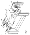
- the device which is the subject of the invention comprises two lateral flanges 1 and 2 designed to receive the bearings of the support rollers 3 and 4 respectively.
- the flanges 1 and 2 are respectively mounted on a central shaft 5 and 6 possibly cooled by water circulation. Trees such as 5 and 6 can be protected for example by a lining of a refractory material allowing avoid the presence of water cooling means. This protection of shafts 5, 6 can be produced using an assembly 7 of ceramic fibers compressed.
- the shafts 5 and 6 of the lateral flanges 1 and 2 are driven in rotation respectively by a motor unit 8, 9, the drive being carried out so as to ensure the synchronization of the angular displacements of the flanges side 1, 2 in order to guarantee the position of the support roller (for example the roller 3 in Figure 1) in the working position.
- the respective bearings of the shafts 5 and 6 of the lateral flanges 1 and 2 are mounted on the frame of the oven, on elements of the latter such as 10 and 10 ', on the on the other side of the oven.
- the tape support rollers 3 and 4 are removably mounted on the corresponding side plates 1 and 2 respectively.
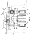
- these flasks have a radial slot or light such as 11, 12 (FIG. 2) intended to respectively receive a bearing from a support roller.
- Each roller bearing supports 3 and 4 is fixed on a counter plate such as 13, 14 using means of suitable fastening, for example by screwing or bolting in order to allow quick and easy disassembly of these bearings.
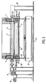
- Each support roll 3 or 4 is rotated through a drive group such as 15 and a double gimbal transmission system as clearly seen in the figure 3, the rotation of each roller being synchronized with the speed of movement of band B.
- Each of said support rollers 3 and 4 is provided with cooling means, these means can be designed or produced so as to further ensure rapid cooling of said rollers, when these are brought into position low, as will be described below, during their evacuation after the operations of permutation.
- the device further comprises a central liftable buffer 16 making it possible to close off the lower opening provided in the bottom of the oven to ensure the evacuation of a support roll such as 3 or 4 from the oven enclosure to the outside, after a permutation operation, as will be described below.
- the central buffer 16 can be moved in a vertical translational movement using a designated double jack system as a whole by reference 17.
- each lifting buffer such as 18 and 19 is provided with a cylinders 20, 20 'mounted respectively on a carriage 21, 22 moving along of a track 23, 24 respectively.
- the tape support roller in use is the roller 3 supported by the pair of lateral flanges 1.
- the roller 4 supported by the side flanges 2 is in the waiting position.
- the first phase of this permutation operation consists in moving down the central buffer 16 in order to allow the rotation of the lateral flanges 1 and 2. This movement is carried out using the jack systems 17 and in FIG. 2, there is shown in broken lines, the position of the tampon central 16 at the end of this first phase. Then, control groups 8 and 9 synchronized rotation drive side flanges 1 and 2 are set action so as to bring the roller 4 into contact with the strip, this roller being driven in rotation synchronized with the running speed of the tape B. Then, the used roller 3 is moved by the rotation of its support flanges 1 so as to move it away from the strip. Note that during this phase of permutation of support rollers, movement synchronization was ensured angles of the side plates 1, 2 supports of the rollers 3 and 4 in order to guarantee the position of a support roller successively 3 and 4 in the working position.
- the jack system 17 ensures the raising of the central buffer 16 in order to close off the lower opening provided in the bottom of the oven (position in solid lines on the Figure 2) and seal the oven.
- the used roller 3 to be removed then rests on its liftable buffer 18 in the high position, this liftable buffer further ensuring the sealing of the opening of the hearth of the furnace during this phase evacuation of the roller 3.
- the bearings of the roller 3 are then disassembled then the latter is released from the slots 11 provided in its support flanges 1.
- the actuator system 20 is then actuated so as to lower the roller 3 supported by the pad 18, which releases this roller from its flanges 1.
- the used roller is then evacuated outside using the carriage 21 and removed by example using an overhead crane.
- the new roller is therefore positioned on the pad 18 and the carriage is moved 21 along its track 23 so as to bring the roller supported by the pad 18 below the position of the flanges 1 intended to support it.
- the actuator system 20 is then actuated in order to raise the buffer 20 to bring the bearings of the new roller engaged in the slots or radial slots 11 provided in the flanges 1.
- the counter plates such as 13 are then fixed ensuring the bearings of the new roller on the flanges 1. This new roller is ready to be put into service when it has to be swapped with roller 4 currently in service.
- the dashed lines show the rotational movements of the flanges 1 and 2 which are generated during this operation swap at the end of which the new roller positioned on the flanges 1 is put into service and the roller 4, which is then the used roller, is then discharged as described above.
- stamp central 16 can be realized in two independent parts, movable separately, by example using separate cylinders.
Landscapes
- Engineering & Computer Science (AREA)
- Chemical & Material Sciences (AREA)
- Mechanical Engineering (AREA)
- Crystallography & Structural Chemistry (AREA)
- Thermal Sciences (AREA)
- Physics & Mathematics (AREA)
- General Engineering & Computer Science (AREA)
- Materials Engineering (AREA)
- Metallurgy (AREA)
- Organic Chemistry (AREA)
- Heat Treatment Of Strip Materials And Filament Materials (AREA)
- Heat Treatments In General, Especially Conveying And Cooling (AREA)
- Closing Of Containers (AREA)
- Tunnel Furnaces (AREA)
Applications Claiming Priority (2)
| Application Number | Priority Date | Filing Date | Title |
|---|---|---|---|
| FR9702365A FR2760077B1 (fr) | 1997-02-27 | 1997-02-27 | Dispositif pour assurer le remplacement d'un rouleau support de bande dans un four de traitement thermique |
| FR9702365 | 1997-02-27 |
Publications (2)
| Publication Number | Publication Date |
|---|---|
| EP0862033A1 true EP0862033A1 (de) | 1998-09-02 |
| EP0862033B1 EP0862033B1 (de) | 2002-11-13 |
Family
ID=9504256
Family Applications (1)
| Application Number | Title | Priority Date | Filing Date |
|---|---|---|---|
| EP98400333A Expired - Lifetime EP0862033B1 (de) | 1997-02-27 | 1998-02-12 | Einrichtung zur Ersetzung einer Bandträgerrolle in einem Wärmebehandlungsofen |
Country Status (6)
| Country | Link |
|---|---|
| US (1) | US5938431A (de) |
| EP (1) | EP0862033B1 (de) |
| JP (1) | JPH10306323A (de) |
| DE (2) | DE69809312T2 (de) |
| ES (1) | ES2119734T3 (de) |
| FR (1) | FR2760077B1 (de) |
Cited By (3)
| Publication number | Priority date | Publication date | Assignee | Title |
|---|---|---|---|---|
| WO2000040766A1 (en) * | 1999-01-06 | 2000-07-13 | Thermtec B.V. | Strip guiding device comprising a rotatable construction for changing supporting rolls having cooling means |
| WO2001011093A1 (en) * | 1999-08-04 | 2001-02-15 | Outokumpu Oyj | Apparatus for supporting material to be treated in continuously operated thermal treatment furnaces |
| EP2737092B1 (de) | 2011-07-25 | 2016-10-12 | Ebner Industrieofenbau GmbH | Rollenwechselvorrichtung für öfen |
Families Citing this family (5)
| Publication number | Priority date | Publication date | Assignee | Title |
|---|---|---|---|---|
| JP4564197B2 (ja) * | 2001-03-27 | 2010-10-20 | 中外炉工業株式会社 | カテナリー型連続熱処理炉用ロール取替え装置 |
| JP4514019B2 (ja) * | 2003-12-02 | 2010-07-28 | 株式会社不二越 | ハースローラ装置及びローラハース炉 |
| JP5038386B2 (ja) * | 2009-12-18 | 2012-10-03 | 中外炉工業株式会社 | カテナリ型炉 |
| JP6756295B2 (ja) * | 2017-04-13 | 2020-09-16 | Jfeスチール株式会社 | シール装置 |
| CN109926895B (zh) * | 2019-02-28 | 2021-03-09 | 北京首钢股份有限公司 | 一种退火炉内炉辊在线修磨控制方法和装置 |
Citations (5)
| Publication number | Priority date | Publication date | Assignee | Title |
|---|---|---|---|---|
| US4049372A (en) * | 1976-05-04 | 1977-09-20 | Allegheny Ludlum Industries, Inc. | Apparatus for supporting and removing a work supporting roll |
| DE3004805A1 (de) * | 1980-02-09 | 1981-10-01 | Sundwiger Eisenhütte Maschinenfabrik Grah & Co, 5870 Hemer | Verfahren und vorrichtung zum auswechseln von tragrollen in rollenherd-durchlaufgluehoefen |
| EP0101931A1 (de) * | 1982-08-13 | 1984-03-07 | Ruhrgas Aktiengesellschaft | Verfahren zum Auswechseln der Rollen eines Durchlauf-Rollenherdofens sowie Ofen zum Durchführen des Verfahrens |
| FR2540138A1 (fr) * | 1983-01-27 | 1984-08-03 | Outokumpu Oy | Dispositif d'appui du materiau en traitement dans des fours de traitement thermique a action continue |
| DE3735542A1 (de) * | 1987-10-21 | 1989-05-03 | Zimmermann & Jansen Gmbh | Rollengang fuer den abtransport von flachglas |
-
1997
- 1997-02-27 FR FR9702365A patent/FR2760077B1/fr not_active Expired - Lifetime
-
1998
- 1998-02-12 DE DE69809312T patent/DE69809312T2/de not_active Expired - Lifetime
- 1998-02-12 DE DE0862033T patent/DE862033T1/de active Pending
- 1998-02-12 EP EP98400333A patent/EP0862033B1/de not_active Expired - Lifetime
- 1998-02-12 ES ES98400333T patent/ES2119734T3/es not_active Expired - Lifetime
- 1998-02-26 US US09/030,960 patent/US5938431A/en not_active Expired - Lifetime
- 1998-02-27 JP JP10046640A patent/JPH10306323A/ja active Pending
Patent Citations (5)
| Publication number | Priority date | Publication date | Assignee | Title |
|---|---|---|---|---|
| US4049372A (en) * | 1976-05-04 | 1977-09-20 | Allegheny Ludlum Industries, Inc. | Apparatus for supporting and removing a work supporting roll |
| DE3004805A1 (de) * | 1980-02-09 | 1981-10-01 | Sundwiger Eisenhütte Maschinenfabrik Grah & Co, 5870 Hemer | Verfahren und vorrichtung zum auswechseln von tragrollen in rollenherd-durchlaufgluehoefen |
| EP0101931A1 (de) * | 1982-08-13 | 1984-03-07 | Ruhrgas Aktiengesellschaft | Verfahren zum Auswechseln der Rollen eines Durchlauf-Rollenherdofens sowie Ofen zum Durchführen des Verfahrens |
| FR2540138A1 (fr) * | 1983-01-27 | 1984-08-03 | Outokumpu Oy | Dispositif d'appui du materiau en traitement dans des fours de traitement thermique a action continue |
| DE3735542A1 (de) * | 1987-10-21 | 1989-05-03 | Zimmermann & Jansen Gmbh | Rollengang fuer den abtransport von flachglas |
Cited By (5)
| Publication number | Priority date | Publication date | Assignee | Title |
|---|---|---|---|---|
| WO2000040766A1 (en) * | 1999-01-06 | 2000-07-13 | Thermtec B.V. | Strip guiding device comprising a rotatable construction for changing supporting rolls having cooling means |
| US6471509B2 (en) | 1999-01-06 | 2002-10-29 | Thermtec B.V. | Strip guiding device comprising a rotatable construction for changing supporting rolls having cooling means |
| WO2001011093A1 (en) * | 1999-08-04 | 2001-02-15 | Outokumpu Oyj | Apparatus for supporting material to be treated in continuously operated thermal treatment furnaces |
| US6682692B1 (en) | 1999-08-04 | 2004-01-27 | Outokumpu Oyj | Apparatus for supporting material to be treated in continuously operated thermal treatment furnaces |
| EP2737092B1 (de) | 2011-07-25 | 2016-10-12 | Ebner Industrieofenbau GmbH | Rollenwechselvorrichtung für öfen |
Also Published As
| Publication number | Publication date |
|---|---|
| DE69809312D1 (de) | 2002-12-19 |
| DE69809312T2 (de) | 2003-09-04 |
| ES2119734T3 (es) | 2003-03-01 |
| US5938431A (en) | 1999-08-17 |
| EP0862033B1 (de) | 2002-11-13 |
| FR2760077B1 (fr) | 1999-04-30 |
| DE862033T1 (de) | 1999-05-06 |
| FR2760077A1 (fr) | 1998-08-28 |
| ES2119734T1 (es) | 1998-10-16 |
| JPH10306323A (ja) | 1998-11-17 |
Similar Documents
| Publication | Publication Date | Title |
|---|---|---|
| EP0862033B1 (de) | Einrichtung zur Ersetzung einer Bandträgerrolle in einem Wärmebehandlungsofen | |
| FR2718995A1 (fr) | Machine d'impression. | |
| EP0908246B1 (de) | Walzenwechselvorrichtung für Arbeitswalzen oder Zwischenwalzen von Walzgerüsten und Einlagerungsvorrichtung | |
| EP0095423A1 (de) | Offset-Druckapparat für verschiedene Formate | |
| CA2164046C (fr) | Dispositif de support d'une face laterale d'une installation de coulee continue de bandes metalliques entre cylindres | |
| EP0742840A1 (de) | Vorrichtung zum verteilen von schuettgut | |
| EP2236296A1 (de) | Vorrichtung und Verfahren zum Markieren oder Etikettieren | |
| EP1129221B1 (de) | Verteilerschurre für schüttgut | |
| FR2601667A1 (fr) | Positionnement des plaques de verre en vue de leur bombage | |
| EP0620061B1 (de) | Vorrichtung zum schnellen Wechseln und Halten einer Seitenwand einer Doppelrollenstranggiessvorrichtung beim Giessen eines Metallproduktes | |
| EP0928682B1 (de) | Vorrichtung zum mechanischen Behandeln von Papier, wobei die Vorrichtung ein verbessertes Lager für eine Walze aufweist und Verfahren zum Austauschen der Walzen in dieser Vorrichtung | |
| FR2737678A1 (fr) | Manipulation de pneumatiques vulcanises, en particulier refroidissement de ceux-ci | |
| EP1775126B1 (de) | Übertragungsvorrichtung von Gegenständen für eine Druckmaschine, Druckmaschine und Übertragungsverfahren | |
| FR2639581A1 (fr) | Chariot porte-groupe d'impression pour une station d'impression dans des machines rotatives | |
| EP1552892A1 (de) | Vorrichtung zum Richten von Metallbändern | |
| EP0071541B1 (de) | Verfahren und Maschine zum Schleifen von Fensterglaskanten | |
| FR2492284A1 (fr) | Laminoir pour tubes d'acier | |
| EP0560662B1 (de) | Verfahren und Anlage zum Walzen einer Metallplatte | |
| FR2702683A1 (fr) | Laminoir à cylindres obliques à deux cylindres, comportant des disques de guidage . | |
| FR2509202A1 (fr) | Laminoir de tubes d'acier comportant un dispositif pour changer les cylindres | |
| EP0593363B1 (de) | Verfahren und Vorrichtung zum Biegen von Glasscheiben | |
| FR3159541A1 (fr) | Outil de laminage pour laminoir circulaire, laminoir circulaire comprenant un tel outil, procédé de laminage au moyen d’un tel laminoir et procédé de maintenance d’un tel laminoir | |
| BE1016068A3 (fr) | Dispositif de manipulation de bord de r uban de verre flotte, et installation mettant en oeuvre un tel dispositif. | |
| GB2124950A (en) | Apparatus for supporting the fixed and rotating guide shoes in a piercing or elongating rolling mill | |
| JPH04270043A (ja) | ビームブランク鋳片のトーチダレ除去装置 |
Legal Events
| Date | Code | Title | Description |
|---|---|---|---|
| PUAI | Public reference made under article 153(3) epc to a published international application that has entered the european phase |
Free format text: ORIGINAL CODE: 0009012 |
|
| AK | Designated contracting states |
Kind code of ref document: A1 Designated state(s): DE ES GB IT NL SE |
|
| AX | Request for extension of the european patent |
Free format text: AL;LT;LV;MK;RO;SI |
|
| GBC | Gb: translation of claims filed (gb section 78(7)/1977) | ||
| REG | Reference to a national code |
Ref country code: ES Ref legal event code: BA2A Ref document number: 2119734 Country of ref document: ES Kind code of ref document: T1 |
|
| TCNL | Nl: translation of patent claims filed | ||
| 17P | Request for examination filed |
Effective date: 19980912 |
|
| DET | De: translation of patent claims | ||
| AKX | Designation fees paid |
Free format text: DE ES GB IT NL SE |
|
| RBV | Designated contracting states (corrected) |
Designated state(s): DE ES GB IT NL SE |
|
| GRAG | Despatch of communication of intention to grant |
Free format text: ORIGINAL CODE: EPIDOS AGRA |
|
| GRAG | Despatch of communication of intention to grant |
Free format text: ORIGINAL CODE: EPIDOS AGRA |
|
| GRAH | Despatch of communication of intention to grant a patent |
Free format text: ORIGINAL CODE: EPIDOS IGRA |
|
| 17Q | First examination report despatched |
Effective date: 20020521 |
|
| GRAH | Despatch of communication of intention to grant a patent |
Free format text: ORIGINAL CODE: EPIDOS IGRA |
|
| GRAA | (expected) grant |
Free format text: ORIGINAL CODE: 0009210 |
|
| AK | Designated contracting states |
Kind code of ref document: B1 Designated state(s): DE ES GB IT NL SE |
|
| REG | Reference to a national code |
Ref country code: GB Ref legal event code: FG4D Free format text: NOT ENGLISH |
|
| REF | Corresponds to: |
Ref document number: 69809312 Country of ref document: DE Date of ref document: 20021219 |
|
| GBT | Gb: translation of ep patent filed (gb section 77(6)(a)/1977) |
Effective date: 20030108 |
|
| REG | Reference to a national code |
Ref country code: ES Ref legal event code: FG2A Ref document number: 2119734 Country of ref document: ES Kind code of ref document: T3 |
|
| PLBE | No opposition filed within time limit |
Free format text: ORIGINAL CODE: 0009261 |
|
| STAA | Information on the status of an ep patent application or granted ep patent |
Free format text: STATUS: NO OPPOSITION FILED WITHIN TIME LIMIT |
|
| 26N | No opposition filed |
Effective date: 20030814 |
|
| PGFP | Annual fee paid to national office [announced via postgrant information from national office to epo] |
Ref country code: GB Payment date: 20050202 Year of fee payment: 8 |
|
| PGFP | Annual fee paid to national office [announced via postgrant information from national office to epo] |
Ref country code: NL Payment date: 20050214 Year of fee payment: 8 |
|
| PG25 | Lapsed in a contracting state [announced via postgrant information from national office to epo] |
Ref country code: GB Free format text: LAPSE BECAUSE OF NON-PAYMENT OF DUE FEES Effective date: 20060212 |
|
| PGFP | Annual fee paid to national office [announced via postgrant information from national office to epo] |
Ref country code: IT Payment date: 20060228 Year of fee payment: 9 |
|
| PG25 | Lapsed in a contracting state [announced via postgrant information from national office to epo] |
Ref country code: NL Free format text: LAPSE BECAUSE OF NON-PAYMENT OF DUE FEES Effective date: 20060901 |
|
| GBPC | Gb: european patent ceased through non-payment of renewal fee |
Effective date: 20060212 |
|
| NLV4 | Nl: lapsed or anulled due to non-payment of the annual fee |
Effective date: 20060901 |
|
| PG25 | Lapsed in a contracting state [announced via postgrant information from national office to epo] |
Ref country code: IT Free format text: LAPSE BECAUSE OF NON-PAYMENT OF DUE FEES Effective date: 20070212 |
|
| PGFP | Annual fee paid to national office [announced via postgrant information from national office to epo] |
Ref country code: SE Payment date: 20130130 Year of fee payment: 16 Ref country code: ES Payment date: 20130207 Year of fee payment: 16 Ref country code: DE Payment date: 20130124 Year of fee payment: 16 |
|
| REG | Reference to a national code |
Ref country code: DE Ref legal event code: R119 Ref document number: 69809312 Country of ref document: DE |
|
| REG | Reference to a national code |
Ref country code: SE Ref legal event code: EUG |
|
| PG25 | Lapsed in a contracting state [announced via postgrant information from national office to epo] |
Ref country code: SE Free format text: LAPSE BECAUSE OF NON-PAYMENT OF DUE FEES Effective date: 20140213 |
|
| REG | Reference to a national code |
Ref country code: DE Ref legal event code: R119 Ref document number: 69809312 Country of ref document: DE Effective date: 20140902 |
|
| PG25 | Lapsed in a contracting state [announced via postgrant information from national office to epo] |
Ref country code: DE Free format text: LAPSE BECAUSE OF NON-PAYMENT OF DUE FEES Effective date: 20140902 |
|
| REG | Reference to a national code |
Ref country code: ES Ref legal event code: FD2A Effective date: 20150406 |
|
| PG25 | Lapsed in a contracting state [announced via postgrant information from national office to epo] |
Ref country code: ES Free format text: LAPSE BECAUSE OF NON-PAYMENT OF DUE FEES Effective date: 20140213 |