EP0862101B1 - Amortissement de résonance dans un régulateur de débit - Google Patents
Amortissement de résonance dans un régulateur de débit Download PDFInfo
- Publication number
- EP0862101B1 EP0862101B1 EP98101863A EP98101863A EP0862101B1 EP 0862101 B1 EP0862101 B1 EP 0862101B1 EP 98101863 A EP98101863 A EP 98101863A EP 98101863 A EP98101863 A EP 98101863A EP 0862101 B1 EP0862101 B1 EP 0862101B1
- Authority
- EP
- European Patent Office
- Prior art keywords
- pressure
- chamber
- responsive member
- pressure responsive
- flow
- Prior art date
- Legal status (The legal status is an assumption and is not a legal conclusion. Google has not performed a legal analysis and makes no representation as to the accuracy of the status listed.)
- Expired - Lifetime
Links
Images

Classifications
-
- G—PHYSICS
- G05—CONTROLLING; REGULATING
- G05D—SYSTEMS FOR CONTROLLING OR REGULATING NON-ELECTRIC VARIABLES
- G05D16/00—Control of fluid pressure
- G05D16/02—Modifications to reduce the effects of instability, e.g. due to vibrations, friction, abnormal temperature, overloading or imbalance
-
- F—MECHANICAL ENGINEERING; LIGHTING; HEATING; WEAPONS; BLASTING
- F16—ENGINEERING ELEMENTS AND UNITS; GENERAL MEASURES FOR PRODUCING AND MAINTAINING EFFECTIVE FUNCTIONING OF MACHINES OR INSTALLATIONS; THERMAL INSULATION IN GENERAL
- F16K—VALVES; TAPS; COCKS; ACTUATING-FLOATS; DEVICES FOR VENTING OR AERATING
- F16K47/00—Means in valves for absorbing fluid energy
-
- F—MECHANICAL ENGINEERING; LIGHTING; HEATING; WEAPONS; BLASTING
- F16—ENGINEERING ELEMENTS AND UNITS; GENERAL MEASURES FOR PRODUCING AND MAINTAINING EFFECTIVE FUNCTIONING OF MACHINES OR INSTALLATIONS; THERMAL INSULATION IN GENERAL
- F16K—VALVES; TAPS; COCKS; ACTUATING-FLOATS; DEVICES FOR VENTING OR AERATING
- F16K47/00—Means in valves for absorbing fluid energy
- F16K47/01—Damping of valve members
-
- G—PHYSICS
- G05—CONTROLLING; REGULATING
- G05D—SYSTEMS FOR CONTROLLING OR REGULATING NON-ELECTRIC VARIABLES
- G05D16/00—Control of fluid pressure
- G05D16/20—Control of fluid pressure characterised by the use of electric means
- G05D16/2093—Control of fluid pressure characterised by the use of electric means with combination of electric and non-electric auxiliary power
- G05D16/2095—Control of fluid pressure characterised by the use of electric means with combination of electric and non-electric auxiliary power using membranes within the main valve
Definitions
- the present invention relates to flow regulators and particularly flow regulators employed for compressible fluid flow control and more particularly relates to such regulators which are supplied with a fluid pressure signal which is modulated by an electrically remote controlled bleed valve for controlling the pressure applied to one side of a pressure responsive member.
- Regulators of this type typically have a moveable valve member attached to the opposite side of the pressure responsive member for controlling flow over a valve seat of the compressible fluid to be flow regulated.
- Regulators of this type are utilized in motor vehicle fuel vapor emission control systems for controlling flow from a fuel vapor purge canister for communication with the charge air inlet of the vehicle engine.
- Purge control regulators of this type are known to utilize the engine manifold depression or vacuum as a fluid pressure signal source for the regulator.
- US-A-3 926 204 shows a flow regulator which comprises a housing which includes a valve for controlling a flow from an inlet port to an outlet port.
- the valve comprises a valve seat and a valve closure member being spring-biased to the closing position.
- a diaphragm is provided which abuts the actuating rot of the valve closure member. The diaphragm moves depending on forces provided by a spring biasing the diaphragm toward the open position of the valve closure member and caused by the pressure in the outlet port.
- a damping weight acts on the closure member at the end opposite to the diaphragm and is arranged between the closure member and the spring biasing the valve closure member toward the closed position.
- the present invention provides a solution to the above-described problem and has a pressure responsive member in the form of a flexible diaphragm dividing a housing into a fluid pressure signal chamber and a fluid pressure flow regulating chamber with the pressure in the signal chamber controlled by an electrically operated bleed valve with the signal chamber connected to a source of fluid pressure which may in an automotive fuel vapor purge system be subatmospheric such as engine inlet manifold depression.
- the flow regulating chamber side of the pressure responsive member includes a valve member moveable with respect to a valve seat for controlling flow between an inlet and outlet of the flow regulator chamber, with the movement of the valve member determined by the differential pressure between the signal chamber and the flow regulating chamber acting upon the pressure responsive member.
- the pressure responsive member has an inertial mass associated therewith for limited relative movement with respect to the pressure responsive member which movement is resiliently resisted.
- the present invention thus provides a flow regulator for controlling flow of compressible fluid, as for example, flow from a fuel vapor purge canister to an engine air inlet of the type which utilizes a pressure responsive member such as the piston or diaphragm with a fluid pressure signal control chamber on one side of the pressure responsive member and a flow regulating chamber on the opposite side of the pressure responsive member.
- the pressure in the fluid pressure signal chamber is controlled by supplying a fluid pressure signal thereto from a convenient source such as engine manifold depression and controlling atmospheric bleed to the chamber by means of an electrically operated bleed valve which may be controlled by a pulse modulated electrical control signal.
- the pressure responsive member has a valve attached thereto for controlling flow over a valve seat disposed between an inlet and outlet passage of the flow regulating chamber; and, the valve movement is dependent upon the differential pressure in between the two chamber acting across the pressure responsive member which has inertial member associated therewith biased for limited movement with respect thereto thereby damping pulsations of the pressure responsive member caused by pressure waves or pulses in the inlet to the regulating chamber.
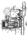
- the flow regulator of the present invention is indicated generally at 10 and has a housing indicated generally at 12 which includes an upper housing shell 14 attached to a lower housing shell 16 which includes an inlet fitting 18 defining therein an inlet passage 20 and an outlet fitting 22 which defines an outlet or discharge passage 24 which communicates with a valve seat 26.
- Inlet passage 20 has disposed therein a restrictor which has a plurality of radially extending grooves or slots 28 formed therein which communicate with an annular passage 30 which is defined by press fitting the restrictor member 32 into the passage 20.
- Restrictor 32 also has a central aperture 34 at its inlet end which communicates with a plurality of smaller apertures 36 provided at the outlet end thereof.
- inlet fitting 18 has an annular seal 38 received thereover and a backup support ring 40 provided adjacent thereto with an adaptor fitting 42 received thereover.
- Fitting 42 preferably has a plurality of annular barbs 44, 46 provided adjacent the right hand end thereof.
- the barbs 44, 46 have received thereover one end of a flexible supply tube or hose 48 with the opposite end of the hose 48 received over a similarly barbed fitting 50 provided on the wall of a supply source such as a fuel vapor purge canister 52.
- a pressure responsive means indicated generally at 52 includes a flexible diaphragm 54 preferably formed of elastomeric material and sealed about its periphery between the upper shall 14 and the lower shell 16 and a piston or backing plate member 56 disposed on the upper surface of the diaphragm 54.
- the piston 52 and diaphragm thus divide the housing 12 into an upper signal pressure chamber 58 and a lower fluid flow regulating pressure chamber 60.
- the piston 56 has a tower or guide portion 62 provided centrally thereon which has received thereover one end of a preload spring 64, with the upper end of the spring registered against a seating washer 66 which is supported on the lower end of an adjustment screw threadedly received in a depending tubular portion 70 formed in the upper housing shell 14.
- the piston 56 has a depending portion 72 over which is received a valve obturator 74 which is preferably integrally formed as one piece with the elastomeric diaphragm 54.
- the valving member or obturator 74 is operable to move with respect to stationary valve seat 26 and to seat thereupon in the closed condition.
- the flow regulating chamber 60 has provided therein a flow dampener in the form of a disc-shaped member 76 which has provided therethrough a plurality of flow dampening orifices 78.
- the pressure in fluid signal chamber 58 is controlled by a fluid pressure signal applied through inlet passage 80 formed in the wall of upper housing shell 14 and communicates exteriorly through a fitting 81 provided on housing shell 14.
- the fluid pressure signal provided at fitting 81 may be provided from any convenient source (not shown) such as, for example, by connection to an engine inlet manifold for the subatmospheric or vacuum pressure provided therein.
- a port 82 is formed in the wall of housing shell 14; and, port 82 communicates with a corresponding port 84 provided at one end of an electrically operated valve indicated generally at 86.
- the valve 86 includes a magnetic armature plate 88 biased upwardly by a spring 90 to close against one end of a valve seat member 92 received over the end of a tubular pole piece 94 which communicates through a filter 96 with an annular outlet passage 98 provided between the upper end of valve body 100 and a protective cap 102.
- Valve seat 92 is received in one end of a bobbin 104 which has wound thereabout a solenoid coil 106 which has thereover an L-shaped pole frame 108 capped with a washer 109 which are operative for conducting magnetic flux externally about the coil.
- tube 94 serves as an armature to move plate 88 toward valve seat 92 which reduces venting of the chamber 58 through port 82.
- Coil 106 is connected to terminal connectors such as connector 110 for external electrical connection thereto.
- valve 86 receives an electrical signal to control the opening of the valve to permit flow through bleed port 84 to control the pressure in chamber 58.
- signal port fitting 81 is connected to a source of subatmospheric pressure or vacuum such as the engine intake manifold.
- Signal orifice 80 controls the rate at which air within chamber 58 is evacuated through port fitting 81. Air is allowed to flow into chamber 58 through inlet ports 82 in the housing shell 14 and port 84 in the end of the electrically operated vacuum regulator 86 (EVR).
- EMR electrically operated vacuum regulator
- the EVR includes a magnetically permeable armature plate 88 biased upwardly by a spring 90 to close against one end of a non-magnetic valve seat 92.
- the magnetically permeable pole piece 94 is assembled into valve seat 92 to define a magnetic working air gap between the armature 88 and the pole piece 94.
- Valve seat 92 is pressed into the bore of bobbin 104. The upper side of armature 88 is thus exposed to atmospheric pressure through a central hole in pole piece 94, filter 96 and inlet passage 98.
- coil 106 When coil 106 is energized, armature 88 is magnetically attracted to pole piece 94. As the armature is moved closer to valve seat 92, flow of atmospheric air is restricted and a greater vacuum is drawn in chamber 58 before the pressure differential is enough to unseat armature 88 allowing subatmospheric air to flow into chamber 58. The current through coil 106 is thus controlled to control the vacuum in chamber 58.
- the pressure responsive means 52 has an inertial dampening means indicated generally at 112 provided thereon to prevent vibration of the piston 56 from creating sufficient resonance so as to create a standing wave in the length L of the fluid supply hose 48 as to cause an audibly discernable acoustical phenomenon known as "hoot".
- inertial dampener 112 is shown as comprising a stanchion 114 formed integrally with piston 56 and extending upwardly therefrom with an expanded or mushroom-shaped head 116 formed on the upper end thereof.
- An inertial mass 118 having an annular configuration is received over the stanchion 116 and is retained thereon by a pair of annular elastomeric support rings 120, 122 which are assembled by stretching over the head 116 of stanchion 114.
- Rings 120, 122 retain the annular mass 118 resiliently by engagement of annular groove 124 in ring 122 with the upper surface of the mass 118; and, by engagement of annular groove 126 formed in ring 120 with the lower surface of the inertial pass 118.
- the rings 122, 124 thus suspend the pass 118 vertically between the upper surface of piston 56 and the undersurface of the mushroom head 116 of stanchion 114.
- any pulses transmitted to chamber 60 through the restrictor holes 78 which effect vibration of the pressure responsive means 52 are dampened by the vertical motion of the mass 118 relative to piston 56 against the resilient restraint of the elastomeric rings 120, 122 which results in a mass dampening of the vibration of the pressure responsive means 52, thereby eliminating formation of resonant waves in the supply hose 48.
- an alternate embodiment of the inertial dampener is indicated generally at 150 wherein the pressure responsive means 52' has diaphragm 54' with an integrally formed elastomeric stanchion 152 which extends upwardly through an aperture 154 formed in the piston 56'.
- the stanchion 152 has an enlarged diameter portion 156 which extends radially outwardly beyond the diameter of the aperture 154 substantially to limit or prevent relative motion of the diaphragm 54' with respect to the piston 56'. It will be understood that the stanchion 152 is assembled through the aperture 154 by stretching the elastomeric material with the aid of a reduced diameter pilot portion 158 which is inserted through aperture 154 and pulling of the larger diameter portion 156 through aperture 154.
- Stanchion 152 has an annular groove 160 formed therein into which is received the annular inertial dampening mass 162 which is retained in the groove 160 by inserting the pilot portion of the stanchion 158 through the center aperture of the annular mass 162 and stretching the stanchion 152 and pulling it through the aperture of mass 162.
- the inertial dampener 150 of FIG. 4 functions identically as the inertial dampener 112 of FIG. 2.
- the present invention thus provides a unique and novel technique for eliminating resonance in the fluid supply tube of a flow regulator employing a pressure responsive piston or diaphragm by providing a resiliently mounted inertial dampening mass on the pressure responsive piston or diaphragm which is effective to dampen out pressure pulsations in the flow regulating chamber.
Landscapes
- Engineering & Computer Science (AREA)
- Physics & Mathematics (AREA)
- General Engineering & Computer Science (AREA)
- Fluid Mechanics (AREA)
- General Physics & Mathematics (AREA)
- Automation & Control Theory (AREA)
- Mechanical Engineering (AREA)
- Control Of Fluid Pressure (AREA)
Claims (14)
- Un régulateur de débit de fluide compressible à résonance amortie (10) comprenant:(a) une structure de carter (12) comprenant un organe sensible à la pression (2) qui divise ladite structure (12) en une première chambre de pression de fluide (58) située d'un côté dudit organe (52) et une seconde chambre de pression de fluide (60) située du côté opposé dudit organe (52), ledit organe sensible à la pression (52) comportant un piston (56) qui peut s'y déplacer, ladite structure de carter (12) comportant un orifice à signal de pression de fluide (81) formé dans ladite première chambre (58), ledit orifice à signal (81) étant agencé de façon à pouvoir être raccordé à une source de signal de pression de fluide, ladite structure de carter (12) comportant un orifice de décharge (82) qui fait communiquer ladite première chambre (58) avec l'atmosphère ambiante;(b) une soupape de décharge (86) qui peut être actionnée sélectivement pour commander l'écoulement par ledit orifice de décharge (82);(c) ladite structure de carter (12) comportant un orifice d'entrée d'écoulement de fluide (20) qui communique avec ladite seconde chambre (60), ledit orifice d'entrée (20) étant agencé de façon à pouvoir être raccordé à une source d'écoulement de fluide qui doit être régulée;(d) des moyens (26, 74) pour commander l'écoulement hors de ladite seconde chambre (60) à travers un orifice d'évacuation (24) formé dans ladite seconde chambre (60) en réponse à la différence de pression entre lesdites première et seconde chambres (58, 60), lesdits moyens (26, 74) comprenant un obturateur de soupape (74) raccordé audit organe sensible à la pression (52) de façon à se déplacer solidairement avec lui et une surface de siège de soupape (26); et(e) une masse inertielle (118, 162) et des moyens élastiques (120. 122; 152) pour attacher ladite masse (118, 162) à au moins une partie dudit organe sensible à la pression (52) de façon qu'il puisse effectuer un mouvement relatif limité par rapport audit piston (56), lesdits moyens élastiques (120, 122; 152) d'attache fonctionnant de manière à s'opposer élastiquement audit mouvement relatif limité de sorte que ladite masse inertielle (118. 162) fonctionne pour amortir par inertie les vibrations dudit organe sensible à la pression (52) en réponse à des impulsions et raréfactions de pression qui se produisent dans ladites seconde chambre (60).
- Le régulateur défini dans la revendication 1, dans lequel ladite soupape de décharge (86) est actionnée électriquement.
- Le régulateur défini dans la revendication 1, dans lequel ladite première chambre à pression de fluide (58) est une chambre à dépression.
- Le régulateur défini dans la revendication 1, dans lequel ladite soupape de décharge (86) est une soupape actionnée électriquement agencée de façon à être commandée par un signal modulé par impulsions de largeur variable.
- Le régulateur défini dans la revendication 1, dans lequel ledit obturateur (74) est un organe en matière élastomère fixé audit organe sensible à la pression (52).
- Le régulateur défini dans la revendication 1, dans lequel ladite structure de carter (12) comporte des moyens (64, 68) sollicitant ledit organe sensible à la pression (52) dans une direction qui s'oppose aux forces de pression d'une pression sub-atmosphérique régnant dans ladite première chambre (52).
- Le régulateur défini dans la revendication 1, dans lequel ledit organe sensible à la pression (52) comporte un diaphragme flexible (54).
- Le régulateur défini dans la revendication 1, dans lequel ladite masse inertielle (118, 162) comporte un organe annulaire monté élastiquement sur ledit organe sensible à la pression (52).
- Le régulateur défini dans la revendication 1, dans lequel ledit organe sensible à la pression (52) comporte un diaphragme en matière élastomère (54) sur lequel est formée en une seule pièce avec lui une colonnette (152); et dans lequel ladite masse inertielle (160) comporte un organe annulaire monté sur ladite colonnette (152).
- Un procédé pour amortir la résonance dans un régulateur de débit de fluide compressible (10) comprenant les étapes qui consistent:(a) à se procurer un organe sensible à la pression (52) comprenant un piston (52) qui peut se déplacer avec lui, à former une chambre de commande de pression de fluide (58) d'un côté dudit organe et à former une chambre à pression de commande de débit (60) du côté opposé audit premier côté, et à former un orifice de décharge faisant communiquer ladite chambre de commande à pression de fluide (58) avec l'atmosphère ambiante;(b) à raccorder une soupape de décharge actionnable sélectivement (86) audit orifice de décharge (82) et à commander la pression dans ladite chambre de commande (58);(c) à raccorder ladite chambre de commande de débit (60) à une source de fluide compressible dont le débit doit être régulé et à relier par un orifice ladite chambre de commande de débit (60) à une conduite d'évacuation d'écoulement (24) et à déplacer un obturateur (74) raccordé audit organe sensible à la pression (52) et à commander l'écoulement dans ledit orifice au moyen dudit obturateur; et(d) à attacher élastiquement une masse inertielle (118, 160) à au moins une partie dudit organe sensible à la pression (52) et à permettre un mouvement limité de ladite masse (118, 150) par rapport audit organe (52) et à amortir par inertie ledit organe sensible à la pression (52) en réponse aux impulsions et raréfactions de pression qui se produisent dans ladite chambre de commande de débit (58).
- Le procédé défini dans la revendication 10, dans lequel ladite étape d'attachement élastique comporte l'étape qui consiste à former un diaphragme en matière élastomère et à former en une seule pièce avec lui une colonnette en matière élastomère (152) et à monter sur elle une masse annulaire (160).
- Le procédé défini dans la revendication 10, dans lequel ladite étape de commande comporte l'étape qui consiste à commander électriquement l'écoulement par une soupape de ladite chambre à pression de commande (58) en réponse à un signal de commande électrique.
- Le procédé défini dans la revendication 10, dans lequel ladite étape de commande comporte l'étape qui consiste à appliquer des impulsions à une soupape à commande électrique (86).
- Le procédé défini dans la revendication 10, dans lequel ladite étape d'attachement élastique comporte l'étape qui consiste à permettre un mouvement relatif limité entre ladite masse (118, 160) et ledit organe sensible à la pression (52) et à s'opposer élastiquement audit mouvement relatif.
Applications Claiming Priority (2)
| Application Number | Priority Date | Filing Date | Title |
|---|---|---|---|
| US08/808,557 US5853018A (en) | 1997-02-28 | 1997-02-28 | Dampening resonance in a flow regulator |
| US808557 | 1997-02-28 |
Publications (2)
| Publication Number | Publication Date |
|---|---|
| EP0862101A1 EP0862101A1 (fr) | 1998-09-02 |
| EP0862101B1 true EP0862101B1 (fr) | 2002-01-16 |
Family
ID=25199112
Family Applications (1)
| Application Number | Title | Priority Date | Filing Date |
|---|---|---|---|
| EP98101863A Expired - Lifetime EP0862101B1 (fr) | 1997-02-28 | 1998-02-04 | Amortissement de résonance dans un régulateur de débit |
Country Status (3)
| Country | Link |
|---|---|
| US (1) | US5853018A (fr) |
| EP (1) | EP0862101B1 (fr) |
| DE (1) | DE69803132T2 (fr) |
Families Citing this family (16)
| Publication number | Priority date | Publication date | Assignee | Title |
|---|---|---|---|---|
| US5921261A (en) * | 1997-05-08 | 1999-07-13 | Eaton Corporation | Dampening resonance in a flow regulator |
| US6016690A (en) * | 1997-09-05 | 2000-01-25 | Siemens Canada Limited | Automotive evaporative emission leak detection system and method |
| US6053151A (en) * | 1997-09-08 | 2000-04-25 | Siemens Canada Limited | Automotive evaporative emission leak detection system and module |
| US5967099A (en) * | 1998-06-12 | 1999-10-19 | Competition Cams, Inc. | System, method, and device for nitrous oxide injection |
| CN1312900A (zh) * | 1998-08-13 | 2001-09-12 | 法克有限公司 | 气体药筒驱动的隔离阀 |
| US6119661A (en) * | 1998-08-18 | 2000-09-19 | Eaton Corporation | Pressure compensating vapor management valve |
| US6015133A (en) * | 1999-04-27 | 2000-01-18 | Eaton Corporation | Fuel vapor managment valve |
| US6412586B1 (en) * | 1999-05-27 | 2002-07-02 | International Truck Intellectual Property Company, L.L.C. | Toroidal exhaust vibration absorber |
| JP2001099016A (ja) * | 1999-09-30 | 2001-04-10 | Denso Corp | 圧力制御弁 |
| US6330878B1 (en) * | 2000-05-31 | 2001-12-18 | Siemens Canada Limited | Evaporative emission leak detection system including vacuum regulator with sensitive seal |
| US6540029B2 (en) | 2001-02-23 | 2003-04-01 | Fike Corporation | Deflagration and explosion suppression and isolation apparatus for contained hazardous material |
| US20070256670A1 (en) * | 2006-05-05 | 2007-11-08 | Siemens Canada Limited | Integrated vacuum blocking valve |
| US20110100336A1 (en) * | 2009-11-04 | 2011-05-05 | Genz Thomas R | Vapor recovery system having vacuum break fitting with flow restrictor |
| US9970572B2 (en) * | 2014-10-30 | 2018-05-15 | Dunan Microstaq, Inc. | Micro-electric mechanical system control valve and method for controlling a sensitive fluid |
| WO2022170414A1 (fr) | 2021-02-12 | 2022-08-18 | Drill Safe Systems Inc. | Dispositifs de régulation de fond de trou de forage et procédés associés |
| US12292059B2 (en) | 2022-03-08 | 2025-05-06 | Inflow Systems Inc. | Intakes and gas separators for downhole pumps, and related apparatuses and methods |
Family Cites Families (16)
| Publication number | Priority date | Publication date | Assignee | Title |
|---|---|---|---|---|
| US2318721A (en) * | 1941-01-11 | 1943-05-11 | Union Carbide & Carbon Corp | Fluid pressure regulator |
| US3857401A (en) * | 1972-06-05 | 1974-12-31 | G Khanin | Method of eliminating vibrations of the regulating valve |
| US3926204A (en) * | 1974-05-17 | 1975-12-16 | Fairchild Industries | Pressure regulator |
| JPS5618182A (en) * | 1979-07-23 | 1981-02-20 | Hitachi Ltd | Feed water valve |
| US4450863A (en) * | 1981-05-13 | 1984-05-29 | Eaton Corporation | Series connected solenoid appliance control valve assembly |
| US4715396A (en) * | 1981-10-16 | 1987-12-29 | Borg-Warner Corporation | Proportional solenoid valve |
| US4500067A (en) * | 1983-02-07 | 1985-02-19 | Eaton Corporation | Pilot operated low flow valve |
| US4844112A (en) * | 1988-09-30 | 1989-07-04 | Eaton Corporation | Electrically operated valve assembly |
| JP2997751B2 (ja) * | 1990-10-31 | 2000-01-11 | ヤマハ発動機株式会社 | 電磁弁装置 |
| US5082240A (en) * | 1990-12-12 | 1992-01-21 | Emerson Electric Co. | Quiet water valve |
| US5213303A (en) * | 1992-03-05 | 1993-05-25 | Southwest Fabricators Corp. | Solenoid actuated valve with adjustable flow control |
| US5299592A (en) * | 1993-01-08 | 1994-04-05 | Eaton Corporation | High pressure relief system |
| US5277167A (en) * | 1993-02-04 | 1994-01-11 | Lectron Products, Inc. | Vapor management valve |
| US5487528A (en) * | 1993-04-22 | 1996-01-30 | Emerson Electric Co. | Quiet appliance water valve |
| US5429099A (en) * | 1994-09-08 | 1995-07-04 | Lectron Products, Inc. | Anti-permeation filter for vapor management valve |
| US5579741A (en) * | 1995-11-30 | 1996-12-03 | Siemens Electric Limited | Vapor purge valve having tapered bead armature seal |
-
1997
- 1997-02-28 US US08/808,557 patent/US5853018A/en not_active Expired - Fee Related
-
1998
- 1998-02-04 EP EP98101863A patent/EP0862101B1/fr not_active Expired - Lifetime
- 1998-02-04 DE DE69803132T patent/DE69803132T2/de not_active Expired - Fee Related
Also Published As
| Publication number | Publication date |
|---|---|
| DE69803132D1 (de) | 2002-02-21 |
| DE69803132T2 (de) | 2002-08-29 |
| US5853018A (en) | 1998-12-29 |
| EP0862101A1 (fr) | 1998-09-02 |
Similar Documents
| Publication | Publication Date | Title |
|---|---|---|
| US5853018A (en) | Dampening resonance in a flow regulator | |
| US5277167A (en) | Vapor management valve | |
| US5429099A (en) | Anti-permeation filter for vapor management valve | |
| US5413082A (en) | Canister purge system having improved purge valve | |
| US5649687A (en) | Pulse width modulated solenoid purge valve | |
| US5509395A (en) | Canister purge flow regulator | |
| US6974120B2 (en) | Solenoid fuel drain valve | |
| US4469079A (en) | Exhaust gas recirculation (EGR) system | |
| US4524948A (en) | Electrically controlled pressure transducer valve | |
| CA2104115A1 (fr) | Electrovanne a purge amelioree en marche au ralenti du moteur | |
| US5551406A (en) | Canister purge system having improved purge valve | |
| EP0826105A1 (fr) | Systeme de purge de reservoir a vapeur a commande de vanne de purge perfectionnee | |
| US4869461A (en) | Canister purge valve with resilient armature | |
| US5921261A (en) | Dampening resonance in a flow regulator | |
| US5941267A (en) | Electrically controlled flow regulator valve with transient dampening | |
| US6015133A (en) | Fuel vapor managment valve | |
| US6119661A (en) | Pressure compensating vapor management valve | |
| US4347699A (en) | Exhaust cleaning fluid control system and vacuum control valve device for use therein | |
| JPH0333472A (ja) | 圧力調整器 | |
| MXPA99003317A (es) | Valvula reguladora de flujo, controlada electricamente, con amortiguamiento transiente | |
| JPS6232268A (ja) | 負圧調整器 | |
| JPH0619674B2 (ja) | 負圧調整器 | |
| JPS62118040A (ja) | エアコントロ−ルバルブ | |
| JPS6321361A (ja) | 機関の燃料圧力調整装置 |
Legal Events
| Date | Code | Title | Description |
|---|---|---|---|
| PUAI | Public reference made under article 153(3) epc to a published international application that has entered the european phase |
Free format text: ORIGINAL CODE: 0009012 |
|
| AK | Designated contracting states |
Kind code of ref document: A1 Designated state(s): DE FR GB |
|
| AX | Request for extension of the european patent |
Free format text: AL;LT;LV;MK;RO;SI |
|
| 17P | Request for examination filed |
Effective date: 19990224 |
|
| AKX | Designation fees paid |
Free format text: DE FR GB |
|
| RBV | Designated contracting states (corrected) |
Designated state(s): DE FR GB |
|
| 17Q | First examination report despatched |
Effective date: 19990507 |
|
| GRAG | Despatch of communication of intention to grant |
Free format text: ORIGINAL CODE: EPIDOS AGRA |
|
| GRAG | Despatch of communication of intention to grant |
Free format text: ORIGINAL CODE: EPIDOS AGRA |
|
| GRAH | Despatch of communication of intention to grant a patent |
Free format text: ORIGINAL CODE: EPIDOS IGRA |
|
| GRAH | Despatch of communication of intention to grant a patent |
Free format text: ORIGINAL CODE: EPIDOS IGRA |
|
| GRAA | (expected) grant |
Free format text: ORIGINAL CODE: 0009210 |
|
| REG | Reference to a national code |
Ref country code: GB Ref legal event code: IF02 |
|
| AK | Designated contracting states |
Kind code of ref document: B1 Designated state(s): DE FR GB |
|
| REF | Corresponds to: |
Ref document number: 69803132 Country of ref document: DE Date of ref document: 20020221 |
|
| ET | Fr: translation filed | ||
| PLBE | No opposition filed within time limit |
Free format text: ORIGINAL CODE: 0009261 |
|
| STAA | Information on the status of an ep patent application or granted ep patent |
Free format text: STATUS: NO OPPOSITION FILED WITHIN TIME LIMIT |
|
| 26N | No opposition filed | ||
| PGFP | Annual fee paid to national office [announced via postgrant information from national office to epo] |
Ref country code: FR Payment date: 20060202 Year of fee payment: 9 |
|
| PGFP | Annual fee paid to national office [announced via postgrant information from national office to epo] |
Ref country code: DE Payment date: 20060228 Year of fee payment: 9 |
|
| GBPC | Gb: european patent ceased through non-payment of renewal fee |
Effective date: 20070204 |
|
| REG | Reference to a national code |
Ref country code: FR Ref legal event code: ST Effective date: 20071030 |
|
| PG25 | Lapsed in a contracting state [announced via postgrant information from national office to epo] |
Ref country code: DE Free format text: LAPSE BECAUSE OF NON-PAYMENT OF DUE FEES Effective date: 20070901 |
|
| PG25 | Lapsed in a contracting state [announced via postgrant information from national office to epo] |
Ref country code: GB Free format text: LAPSE BECAUSE OF NON-PAYMENT OF DUE FEES Effective date: 20070204 Ref country code: FR Free format text: LAPSE BECAUSE OF NON-PAYMENT OF DUE FEES Effective date: 20070228 |
|
| PGFP | Annual fee paid to national office [announced via postgrant information from national office to epo] |
Ref country code: GB Payment date: 20060109 Year of fee payment: 9 |