EP0862139A2 - Procédé d'interpolation des données de couleur "tristimulus" - Google Patents
Procédé d'interpolation des données de couleur "tristimulus" Download PDFInfo
- Publication number
- EP0862139A2 EP0862139A2 EP97306121A EP97306121A EP0862139A2 EP 0862139 A2 EP0862139 A2 EP 0862139A2 EP 97306121 A EP97306121 A EP 97306121A EP 97306121 A EP97306121 A EP 97306121A EP 0862139 A2 EP0862139 A2 EP 0862139A2
- Authority
- EP
- European Patent Office
- Prior art keywords
- bits
- nodes
- data
- reducing
- construct
- Prior art date
- Legal status (The legal status is an assumption and is not a legal conclusion. Google has not performed a legal analysis and makes no representation as to the accuracy of the status listed.)
- Withdrawn
Links
Images


Classifications
-
- G—PHYSICS
- G06—COMPUTING OR CALCULATING; COUNTING
- G06T—IMAGE DATA PROCESSING OR GENERATION, IN GENERAL
- G06T3/00—Geometric image transformations in the plane of the image
- G06T3/40—Scaling of whole images or parts thereof, e.g. expanding or contracting
- G06T3/4007—Scaling of whole images or parts thereof, e.g. expanding or contracting based on interpolation, e.g. bilinear interpolation
Definitions
- the present invention relates generally to colorimetry, more particularly to nonlinear tristimulus color data storage, retrieval and interpolation, and, more specifically to memory mapping and data interpolation strategy for 24-bit L*H*C* to 24-bit RGB space data.
- Colorimetry has long been recognized as a complex science. Essentially, as defined in 1931 by the Commission Internationale L'Eclairage (CIE), three primary colors (X, Y, Z) can be combined to define all light sensations we experience with our eyes; that is, the color matching properties of an ideal trichromatic observer defined by specifying three independent functions of wavelength that are identified with the ideal observer's color matching functions form an international standard for specifying color. In general, it has been found possible and convenient to represent color stimuli vectors by a three-dimensional spatial construct, called a tristimulus space or a color space .
- CIE Commission Internationale L'Eclairage
- a variety of trichromatic model systems provide alternatives for both the hardware and software system designers ⁇ e.g., the red, green, blue (RGB) model commonly used in computer video displays; the cyan, magenta, yellow (and black) (CMY(K)) model used extensively in color hard copy apparatus; the hue, saturation, value (HSV) model; the hue, lightness, saturation (HLS) model; the luminance, red-yellow scale, green-blue scale (L*a*b*) model; the YIQ model used in commercial color television broadcasting; and others.
- RGB red, green, blue
- CMY(K) cyan, magenta, yellow (and black)
- HVS hue, lightness, saturation
- L*a*b* luminance, red-yellow scale, green-blue scale
- YIQ used in commercial color television broadcasting
- Color input and output devices - such a scanners, cathode ray tube (CRT) video monitors, and printers - present color images in a device-dependent fashion.
- CRT guns are driven by RGB values (voltage levels or other input signal functions, referred to hereinafter as data triplets or color coordinates ) that are stored in a frame buffer.
- RGB values voltage levels or other input signal functions, referred to hereinafter as data triplets or color coordinates
- Those RGB values index over the color space of each particular model video monitor; in other words, the color produced by a CRT on a pixel of its screen for a given RGB triplet of values is unique to that device. Because of device design dependency, the same RGB triplet may produce a very different color or hue when displayed on a different model CRT and still a different color in a hard copy made with a color printer.
- Color transformation also referred to in the art as color correction and cross-rendering
- color correction and cross-rendering between model systems in digital data processing presents many problems to the original equipment manufacturer.
- the transformation of data from one device to another device is difficult because the color matching relationship between those systems are generally non-linear. Therefore, a crucial problem is the maintaining of color integrity between an original image from an input device (such as a color scanner, CRT monitor, digital camera, computer software/firmware generation, and the like) and a translated copy at an output device (such as a CRT monitor, color laser printer, color ink-jet printer, and the like).
- a transformation from one color space to another requires complex, non-linear computations in multiple dimensions.
- a lookup table of input versus output data can be generated for any set of devices.
- the 1975 U.S. Patent No. 3,893,166 to Pugsley provides an example.
- semiconductor memory is relatively expensive and other data storage technologies for maintaining such tables -- disks, tape, and the like -- are too slow.
- Bytes of data correlated in three dimensions can be represented as a construct, such as a polyhedral lattice, with each corner of a cube representing a data point, that is, a data set having coordinate values in each of the planes is stored in a memory location, or node , as a look-up table.
- node may seem to have multiple meanings because of the nature of multidimensional spatial constructs that are used in such systems; (1) it can refer to the coordinates of the space of an input pixel; (2) it can refer to stored data points between which interpolation of data may occur; (3) when a color data map of multi-dimensional color space is stored in a two-dimensional computer memory, it can refer to the memory address itself which has a one-to-one correspondence with the incoming pixel coordinates; (4) it can refer to the data stored at each memory location that represents the output pixel data which itself can refer to the coordinates of a second spatial point.
- the total look-up table is made of many such cubes as shown in FIGURE 1 for an RGB color space construct.
- to store a typical printer color transformation data point value for every monitor RGB value in a look-up table would require fifty megabytes or more of random access memory which is cost prohibitive in the state-of-the-art.
- trilinear or quadrilinear interpolation methods have been used.
- Transforming input data triplets into printer RGB (or CMY, or CMYK) values also can be accomplished by utilizing color measurement tools and device-independent color spaces.
- Device-independent color provides accurate color matching based on an absolute color standard, such as the CIE.
- a device-independent color space provides a way for describing the appearance of a color without referring to the mechanism that produced the color. For example:
- the mapping of the monitor RGB values into printer RGB values is time intensive to perform on each and every colored pixel in an image before completely printing that image. Therefore, it is economic to pre-compute and store the output data triplets for a subset of input values and then to use a fast interpolation algorithm to approximate the transform function for intermediate output data values i.e., those that have not been pre-computed and stored.
- L*H*C* uses luminance (directional intensity; reflectance or transmittance; "Y” in the CIE standard tristimulus coordinate system), hue, and chroma, generally referred to as simply "LHC,” is cylindrical as shown in FIGURES 2A and 2B , where FIGURE 2B depicts a hue-chroma plane of constant luminance, hue changing along circles of constant chroma. The entire color map consists of these planes stacked on top of each other.
- a scanner produces device-dependent RGB data. It is desirable for an end user to be able to have output print control, but the output data will also be in RGB or CMYK data, also device-dependent. Data control, and hence output control, can be provided in a color space only where there is independence of the variables (e.g.,in RGB, adjusting R would affect any color hue that has a red component, not just red, and both luminance and chroma; similarly with L*a*b* attempted control). Thus, control can only be done in a color space that will not create shifts in other variables. Luminance, L*, hue, H*, and chroma, C* are independent variables. Therefore, it is advantageous to transform RGB input data through a LHC construct because any of the variables can be adjusted independently and thus are readily adaptable to end-user hardware and software preference controls.
- the present invention provides a computerized method for interpolating tristimulus color space data stored in a memory emulating a color space having a tri-variable coordinate cylindrical construct, the data stored as multi-bit data words in the memory constituting tri-variable coordinates of a color space construct having a polyhedral construct, the method comprising the steps of:
- the invention also provides for a computer device having a program for interpolating data, the program comprising the steps of:
- FIGURE 1 (Prior Art) is a schematic depiction of a color space construct for RGB data.
- FIGURES 2A and 2B are schematic depictions of a L*H*C* color space construct.
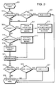
- FIGURE 3 is a flow chart of a method of color mapping and color space data transformation in accordance with the present invention.
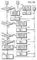
- FIGURES 4A and 4B (a continuation of 4A) is a flow chart of an interpolation methodology in detail of the flow chart as shown in FIGURE 3.
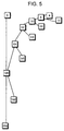
- FIGURE 5 is a depiction of the mapping strategy for nodes of the chroma coordinates of the present invention as an adjunct to TABLE 1.
- FIGURE 3 it is assumed that RGB scanner data has been converted (by any technique as would be known in the state of the art) to LHC data for each pixel of the scanned image. Luminance, hue and chroma control have been provided to the user. It is now necessary to transform LHC input data back into a data triplet recognizable by the printer, e.g., RGB or CMY(K) data. Each triplet of input LHC pixel data is received sequentially, 301.
- any special instructions, or checks, into the routine, 303 For example, the user may have specified a special print media, such as glossy paper, is in use. If the special condition is true ( Y ), a special check of the condition and processing accordingly is implemented. So in this example, if a glossy media mode has been selected, the check is made to see if LHC is for coordinate 0,0,0", 305; if so, RGB is also set to 0,0,0" and output, 329. This may be a reserve indicator that text printing is in process. If the LHC is not 0,0,0", 305 N, or the special condition is not true, 303, N, then the process continues. This subroutine will be explained further with respect to the interpolated data output. First, however, it is important to understand the rules for retrieving predetermined stored data from the color map, also referred to as node fetching and the interpolation process flow.
- RGB output data points are stored in nodes of an addressable memory based upon use of input values of the LHC cylindrical-based color space coordinate system.
- the information stored for each node consists of three bytes, one each for the RGB output values.
- Selection of nodes can be accomplished with the following rules: Assume a set of M points ⁇ N(0), N(1)...N(M) ⁇ , selected from a possible 2 K [i.e., the range from 0 to( 2 K )-1]. This set of nodes will be valid for use with the interpolation methodology of the present invention if and only if the following are all true:
- C* - are stored more frequently in low chroma space (TABLE 1, a non-linear progression of: 0, 4, 8, then 16, 24, 32, then 48, 64, then 96, 128, then 192, then 255). This is also depicted in FIGURE 5 , where the data distribution toward low chroma nodes is dramatically greater than for colors of low chroma value.
- the default number of nodes to be fetched would be eight, all of the surrounding stored nodes of adjacent planes of a polyhedron of a color space construct defined by the fetched nodes (see e.g., FIGURE 1).
- TABLE 1 is required to determine which eight nodes to fetch a comparison of the three LHC components of the incoming pixel 301 with the map node locations. For each of the three components, the map node locations which is less than or equal to the incoming pixel component is determined. Once these three values are determined, the next largest index for each component are determined. Once these six values, two for each component, are determined, you can use the eight possible combinations to find the eight default map nodes from which the correlative RGB data is to be fetched.
- any one of the components of the incoming pixel value exactly matches one of the map node indices, only half the number of fetches required. That is, in a smart-fetch, it can be recognized what an input pixel is and determine which nodes are need such that, depending upon the input color coordinates and their alignment with planes of the sample nodes, all eight surrounding nodes may not be needed. When a match occurs, it limits the choices for that component from two to one to figure out what nodes to fetch.
- no components provide a match, all eight nodes must be fetched; if one component matches, four nodes must be fetched; if two components match, two nodes must be fetched; and if all three components match, only one node must be fetched.
- each node may comprise 24-bits of data but the bus architecture may be only 16-bits wide. In retrieving two nodes, 48-bits of data, a multiple of sixteen is amenable to a straight storage methodology. Storing in sequence as shown in TABLE 2 is acceptable if this were always the case. However, as shown above, the smart-fetch methodology will not always match the bus architecture. Node doubling in memory provides a solution. That is, in order to expedite fetches and decrease DMA bus utilization, most nodes of the color map appear in main memory more than once. The understanding of node doubling comes from an understanding of the nature of the storage and retrieval of the type of data being used in color space transformation.
- a pixel such as number 2 in FIGURE 2B would require such eight adjacent nodes, four from each of the available adjacent L* planes.
- all nodes exist only in one addressable location and a the color map having a hardware convenient 16-bit/word structure, a small segment of which is shown in TABLE 2, would require redundant access steps.
- an ASIC on-board cache memory substantially improves data processing time. That is, it is faster to retrieve data nodes from a cache if the color map is kept off-board the data processing ASIC in general memory.
- the use of an ASIC on-board cache memory can also be used to provide a more efficient fetching methodology. That is, data fetched for a current transformation are cached and remain in the cache memory until the next transformation cycle. Therefore, prior to determining if smart-fetching 315 - 317 is appropriate, a cache check is performed 309 - 313 to determine if the nodes have been retrieved during data transformation from LHC to RGB data in a prior transform cycle.
- a cache is enabled, 309 Y, then the cache memory is checked, for all the input data requested nodes, 311. If not all nodes are found in the cache, the remainder are fetched from main memory, 313, replacing node data not needed for the current transform cycle. In the preferred embodiment, it has been explained that there are seventeen L* value nodes, thirty H* value nodes, and thirteen C* value nodes in the color map (TABLE 1). An appropriate size and addressing scheme for cache memory can be devised for holding data in a set-associative manner as would be known to a person skilled in the art. If all the nodes addressed by the current input LHC pixel coordinates are already in the cache 311, 313, then step 315 - 319 can be bypassed.
- the first step of a data transformation and interpolation from LHC color space input data 301 to RGB (or other device-dependency) color space output data 329 is to determine which of the color map nodes describe the smallest polyhedron, or subcube, that encloses the input pixel.
- the second step is the fetching 315-319 of the data stored at those relevant nodes.
- the third step is the actual interpolation calculation 321; that is, the data of the fetched nodes are interpolated as needed to produce a corresponding 24-bit RGB output value 329 correlated to the input LHC pixel data 301.
- the interpolation subroutine 321 is shown in FIGURES 4A and 4B .
- a set of output RGB coordinates from the input LHC coordinates is to be derived.
- the input LHC coordinate values 400 will come from either cache memory (see FIGURE 3, steps 309-313) or main memory by a smart-fetch (steps 315-317) or a full fetch of all surrounding nodes (step 319).
- the interpolation routine can be improved.
- the L bits count is set to zero, step 401.
- step 405, N H bits is set to the log 2 of the difference between the adjacent map node values, step 406. If true (step 405 Y ), or after step 404, the process proceeds, setting the C bits to zero, step 407, and running a similar routine. The incoming C* value is checked to determine if it coincides with a stored map node, step 408. If the condition is false (step 408, N ), C bits is set to the log 2 of the difference between the adjacent map node values, step 409. If true (step 408 Y ), or after step 408, the next stage of the process is begun.
- L bits , H bits , and C bits are zero, 410, meaning all three coordinates are specific map nodes, no interpolation is necessary, the nodes can be fetched and output, step 329 (see also FIGURE 3). [A second special code check point, 323, will be discussed in further detail below.] If not, an interpolation is run. L bits , H bits , and C bits are compared, step 411. If the condition L bits > H bits AND L bits > C bits is true (step 4111, Y ), based on the bit in the L bits position of the incoming L* value, a half cube reduction toward the designated position in color space along the L* axis is performed, step 412.
- step 413 meaning in the example that only 3-bits of the original 4-bits interpolation designator bits remain.
- the routine returns to step 410 and continues. If the condition of step 411 was false (meaning no interpolation of L* necessary at this level of interpolation), a next comparison is performed.
- step 414 If H bits > L bits AND H bits > C bits , step 414, is true, based on the bit in the H bits position of the incoming H* value, a half cube reduction along the H* axis is performed, step 415; again, moving toward the position in color space where the hue coordinate transform is. H bits is reduced by one, step 416. The routine loops again to step 410 and continues. If the condition of step 414 was false, a next comparison is performed.
- step 417 If C bits > L bits AND C bits > H bits , step 417, is true, based on the bit in the C bits position of the incoming C* value a half cube reduction in the C* axis is performed, step 418. C bits is reduced by one, step 419, and the routine again returns to step 410. If the condition of step 417 is false and next level comparison begins.
- step 420 based on the bit in the L bits position of the incoming L* value and the bit in the H bits position of the incoming H* value, a quarter cube reduction along the L* and H* axes is taken, step 421. L bits and H bits are reduced by one each, step 422, and the process returns to step 410. If the condition of step 420 is false, another comparison test is performed.
- step 423 based on the bit in the L bits position of the incoming L* value and the bit in the C bits position of the incoming C* value, a quarter cube reduction along the L* and C* axes is performed, step 424. L bits and C bits are each reduced by one, step 425, and the process returns to step 410. If the condition of step 423 is false, the next comparison is made.
- step 426 based on the bit in the H bits position of the incoming H* value and the bit in the C bits position of the incoming C* value, a quarter cube reduction along the H* and C* axes is performed, step 427. H bits and C bits are reduced by one each, step 428, and the process returns to step 410. If the condition of step 426 is false, an eight cube reduction in L*, H* and C* axes is taken, step 429. L bits , H bits , and C bits are all reduced by one, step 430, and the process returns to step 410.
- the interpolation process proceeds until the condition of step 410 is satisfied.
- the next input LHC pixel can then be processed and so on until the entire transform from LHC to RGB is completed.
- Another special condition check 323 - 327 can be performed where, as before, reserved values can provide a special output useful to other operational aspects of the apparatus.
- the present invention thus provides a color space data mapping strategy and interpolation methodology for transforming from L*H*C* input pixel coordinate values to RGB (or other tristimulus system) output pixel values.
- Non-linear color space data mapping and improved interpolation provide a more efficient multi-variable data transform.
- the output values are then used in displaying (for example with a hard copy apparatus providing a color print) the transformed data.
- the output values would be used to drive a print head controller to then deposit appropriate drops of color ink onto a print medium to achieve a dot matrix representation of the image.
- a map is stored in main memory; the cache is cleared and the input register purged; and appropriate ENABLE bits for set for the special conditions, cache, and smart-fetch subroutines. Processing of input LHC pixel data can then proceed until the whole image is transformed.
Landscapes
- Physics & Mathematics (AREA)
- General Physics & Mathematics (AREA)
- Engineering & Computer Science (AREA)
- Theoretical Computer Science (AREA)
- Image Processing (AREA)
- Color Television Systems (AREA)
- Controls And Circuits For Display Device (AREA)
- Image Generation (AREA)
- Facsimile Image Signal Circuits (AREA)
Applications Claiming Priority (2)
| Application Number | Priority Date | Filing Date | Title |
|---|---|---|---|
| US08/806,355 US6933949B1 (en) | 1997-02-26 | 1997-02-26 | Method for interpolation of tristimulus color data |
| US806355 | 1997-02-26 |
Publications (2)
| Publication Number | Publication Date |
|---|---|
| EP0862139A2 true EP0862139A2 (fr) | 1998-09-02 |
| EP0862139A3 EP0862139A3 (fr) | 2000-05-10 |
Family
ID=25193859
Family Applications (1)
| Application Number | Title | Priority Date | Filing Date |
|---|---|---|---|
| EP97306121A Withdrawn EP0862139A3 (fr) | 1997-02-26 | 1997-08-12 | Procédé d'interpolation des données de couleur "tristimulus" |
Country Status (3)
| Country | Link |
|---|---|
| US (1) | US6933949B1 (fr) |
| EP (1) | EP0862139A3 (fr) |
| JP (1) | JPH10240918A (fr) |
Families Citing this family (2)
| Publication number | Priority date | Publication date | Assignee | Title |
|---|---|---|---|---|
| US8913073B2 (en) * | 2006-08-09 | 2014-12-16 | Adobe Systems Incorporated | Interpolation according to a function represented using unevenly spaced samples of the function |
| US8368716B2 (en) * | 2008-09-29 | 2013-02-05 | Hewlett-Packard Development Company, L.P. | Processing pixel values of a color image |
Citations (1)
| Publication number | Priority date | Publication date | Assignee | Title |
|---|---|---|---|---|
| EP0487304A2 (fr) * | 1990-11-20 | 1992-05-27 | Canon Kabushiki Kaisha | Traitement d'images en couleurs |
Family Cites Families (12)
| Publication number | Priority date | Publication date | Assignee | Title |
|---|---|---|---|---|
| US3893166A (en) | 1972-01-05 | 1975-07-01 | Crosfield Electronics Ltd | Colour correcting image reproducing methods and apparatus |
| JPS5816180B2 (ja) | 1977-04-01 | 1983-03-30 | 大日本スクリ−ン製造株式会社 | メモリ装置における信号補間方法 |
| US4275413A (en) | 1978-03-30 | 1981-06-23 | Takashi Sakamoto | Linear interpolator for color correction |
| JPS57208765A (en) | 1981-06-18 | 1982-12-21 | Dainippon Screen Mfg Co Ltd | Signal interpolating method for memory device |
| US4477833A (en) | 1981-08-12 | 1984-10-16 | R. R. Donnelley & Sons Company | Method of color conversion with improved interpolation |
| US4500919A (en) * | 1982-05-04 | 1985-02-19 | Massachusetts Institute Of Technology | Color reproduction system |
| EP0273398B1 (fr) * | 1986-12-25 | 1995-02-08 | Konica Corporation | Procédé de correction d'images en couleurs |
| US5121196A (en) | 1988-11-18 | 1992-06-09 | Konica Corporation | Color processing method and apparatus with a color patch |
| US5321797A (en) * | 1990-06-11 | 1994-06-14 | Eastman Kodak Company | Apparatus and method for performing coordinate transformation employing stored values and interpolation |
| JP2903807B2 (ja) | 1991-10-17 | 1999-06-14 | 富士ゼロックス株式会社 | 色信号変換方法および装置 |
| US5343311A (en) * | 1992-04-14 | 1994-08-30 | Electronics For Imaging, Inc. | Indexed processing of color image data |
| US5740344A (en) * | 1996-02-08 | 1998-04-14 | Itri-Industrial Technology Research Institute | Texture filter apparatus for computer graphics system |
-
1997
- 1997-02-26 US US08/806,355 patent/US6933949B1/en not_active Expired - Fee Related
- 1997-07-29 JP JP9202846A patent/JPH10240918A/ja active Pending
- 1997-08-12 EP EP97306121A patent/EP0862139A3/fr not_active Withdrawn
Patent Citations (1)
| Publication number | Priority date | Publication date | Assignee | Title |
|---|---|---|---|---|
| EP0487304A2 (fr) * | 1990-11-20 | 1992-05-27 | Canon Kabushiki Kaisha | Traitement d'images en couleurs |
Also Published As
| Publication number | Publication date |
|---|---|
| US6933949B1 (en) | 2005-08-23 |
| JPH10240918A (ja) | 1998-09-11 |
| EP0862139A3 (fr) | 2000-05-10 |
Similar Documents
| Publication | Publication Date | Title |
|---|---|---|
| US5870077A (en) | Method for tristimulus color data non-linear storage, retrieval, and interpolation | |
| US5343311A (en) | Indexed processing of color image data | |
| US5553199A (en) | Method and apparatus for calibrating a four color printer | |
| EP0700198B1 (fr) | Système pour la correction de données d'image couleur avec interpolation tétraédrique sur un grillage hexagonal | |
| US5963201A (en) | Color processing system | |
| US5909291A (en) | Color matching apparatus and method | |
| US5504821A (en) | Color converting apparatus for performing a three-dimensional color conversion of a colored picture in a color space with a small capacity of memory | |
| US5208911A (en) | Method and apparatus for storing and communicating a transform definition which includes sample values representing an input/output relation of an image transformation | |
| US5448380A (en) | color image processing method and apparatus for correcting a color signal from an input image device | |
| US6005968A (en) | Scanner calibration and correction techniques using scaled lightness values | |
| US6766051B2 (en) | Adaptive tree-base lookup for non-separably divided color tables | |
| US5596510A (en) | Table-based linear interpolation for color correction system and method | |
| EP0703701A2 (fr) | Système de traitement d'image en couleur servant à préparer un module de transformation d'images composites pour effectuer une pluralité de transformation d'images sélectionnées | |
| US6707938B2 (en) | Principal axis look-up for color correction | |
| US5748176A (en) | Multi-variable colorimetric data access by iterative interpolation and subdivision | |
| JPH0795431A (ja) | 色較正のための凸補間の方法および装置 | |
| EP1221812B1 (fr) | Interpolation rapide des grande tables de consultation couleurs | |
| JP3976849B2 (ja) | 補間器入力データを生成する装置 | |
| US6137495A (en) | Method for storing, accessing, transforming, and displaying multi-variable digital data | |
| US5666436A (en) | Method and apparatus for transforming a source image to an output image | |
| US6002795A (en) | Method and apparatus for transforming a source image to an output image | |
| EP1011263B1 (fr) | Procédé de correction de couleurs par demi-teintes à plusieurs niveaux | |
| US6933949B1 (en) | Method for interpolation of tristimulus color data | |
| WO1996039774A1 (fr) | Systeme de mise en antememoire pour traitement d'interpolation | |
| JPH10150578A (ja) | カラー画像変換方法 |
Legal Events
| Date | Code | Title | Description |
|---|---|---|---|
| PUAI | Public reference made under article 153(3) epc to a published international application that has entered the european phase |
Free format text: ORIGINAL CODE: 0009012 |
|
| AK | Designated contracting states |
Kind code of ref document: A2 Designated state(s): DE FR GB |
|
| AX | Request for extension of the european patent |
Free format text: AL;LT;LV;RO;SI |
|
| PUAL | Search report despatched |
Free format text: ORIGINAL CODE: 0009013 |
|
| AK | Designated contracting states |
Kind code of ref document: A3 Designated state(s): AT BE CH DE DK ES FI FR GB GR IE IT LI LU MC NL PT SE |
|
| AX | Request for extension of the european patent |
Free format text: AL;LT;LV;RO;SI |
|
| 17P | Request for examination filed |
Effective date: 20000705 |
|
| AKX | Designation fees paid |
Free format text: DE FR GB |
|
| RAP1 | Party data changed (applicant data changed or rights of an application transferred) |
Owner name: HEWLETT-PACKARD COMPANY, A DELAWARE CORPORATION |
|
| 17Q | First examination report despatched |
Effective date: 20021128 |
|
| 17Q | First examination report despatched |
Effective date: 20021128 |
|
| STAA | Information on the status of an ep patent application or granted ep patent |
Free format text: STATUS: THE APPLICATION IS DEEMED TO BE WITHDRAWN |
|
| 18D | Application deemed to be withdrawn |
Effective date: 20070305 |