EP0862143A2 - Verfahren und Anordnung zur Erzeugung und Überprüfung eines Sicherheitsabdruckes - Google Patents
Verfahren und Anordnung zur Erzeugung und Überprüfung eines Sicherheitsabdruckes Download PDFInfo
- Publication number
- EP0862143A2 EP0862143A2 EP98250018A EP98250018A EP0862143A2 EP 0862143 A2 EP0862143 A2 EP 0862143A2 EP 98250018 A EP98250018 A EP 98250018A EP 98250018 A EP98250018 A EP 98250018A EP 0862143 A2 EP0862143 A2 EP 0862143A2
- Authority
- EP
- European Patent Office
- Prior art keywords
- data
- window
- postage meter
- sub
- meter machine
- Prior art date
- Legal status (The legal status is an assumption and is not a legal conclusion. Google has not performed a legal analysis and makes no representation as to the accuracy of the status listed.)
- Withdrawn
Links
- 238000000034 method Methods 0.000 title claims abstract description 37
- 239000013598 vector Substances 0.000 claims abstract description 27
- 238000007639 printing Methods 0.000 claims description 96
- 238000004422 calculation algorithm Methods 0.000 claims description 17
- 238000012015 optical character recognition Methods 0.000 claims description 14
- 238000013475 authorization Methods 0.000 claims description 6
- 239000000945 filler Substances 0.000 claims 2
- 230000015654 memory Effects 0.000 description 230
- 238000011156 evaluation Methods 0.000 description 51
- 230000008859 change Effects 0.000 description 35
- 238000007689 inspection Methods 0.000 description 31
- 230000015572 biosynthetic process Effects 0.000 description 22
- 238000004891 communication Methods 0.000 description 22
- 238000012986 modification Methods 0.000 description 16
- 230000004048 modification Effects 0.000 description 16
- 238000006243 chemical reaction Methods 0.000 description 15
- 238000013478 data encryption standard Methods 0.000 description 15
- 230000001419 dependent effect Effects 0.000 description 12
- 238000010586 diagram Methods 0.000 description 7
- 230000003247 decreasing effect Effects 0.000 description 6
- 238000012360 testing method Methods 0.000 description 6
- 238000012795 verification Methods 0.000 description 6
- 230000001174 ascending effect Effects 0.000 description 5
- 238000004364 calculation method Methods 0.000 description 5
- 230000006837 decompression Effects 0.000 description 5
- 238000012545 processing Methods 0.000 description 5
- 230000036962 time dependent Effects 0.000 description 5
- 230000006399 behavior Effects 0.000 description 4
- 230000008901 benefit Effects 0.000 description 4
- 230000000694 effects Effects 0.000 description 4
- 230000008569 process Effects 0.000 description 4
- 238000012546 transfer Methods 0.000 description 4
- 230000000295 complement effect Effects 0.000 description 3
- 238000001514 detection method Methods 0.000 description 3
- 230000006870 function Effects 0.000 description 3
- 238000004458 analytical method Methods 0.000 description 2
- 238000013459 approach Methods 0.000 description 2
- 230000005540 biological transmission Effects 0.000 description 2
- 230000003111 delayed effect Effects 0.000 description 2
- 238000010348 incorporation Methods 0.000 description 2
- 230000033001 locomotion Effects 0.000 description 2
- 238000004519 manufacturing process Methods 0.000 description 2
- 238000005259 measurement Methods 0.000 description 2
- 238000012544 monitoring process Methods 0.000 description 2
- 238000003909 pattern recognition Methods 0.000 description 2
- 230000009467 reduction Effects 0.000 description 2
- 238000007651 thermal printing Methods 0.000 description 2
- 230000009466 transformation Effects 0.000 description 2
- 230000000007 visual effect Effects 0.000 description 2
- 101100402694 Arabidopsis thaliana MSR2 gene Proteins 0.000 description 1
- 101001134216 Homo sapiens Macrophage scavenger receptor types I and II Proteins 0.000 description 1
- 102100034184 Macrophage scavenger receptor types I and II Human genes 0.000 description 1
- 101100043629 Saccharomyces cerevisiae (strain ATCC 204508 / S288c) SSY1 gene Proteins 0.000 description 1
- 206010042635 Suspiciousness Diseases 0.000 description 1
- 230000009471 action Effects 0.000 description 1
- 230000004075 alteration Effects 0.000 description 1
- 230000003466 anti-cipated effect Effects 0.000 description 1
- 230000003190 augmentative effect Effects 0.000 description 1
- 238000011511 automated evaluation Methods 0.000 description 1
- 239000003086 colorant Substances 0.000 description 1
- 230000000052 comparative effect Effects 0.000 description 1
- 238000011161 development Methods 0.000 description 1
- 230000003292 diminished effect Effects 0.000 description 1
- 230000001747 exhibiting effect Effects 0.000 description 1
- 238000005286 illumination Methods 0.000 description 1
- 230000002779 inactivation Effects 0.000 description 1
- 230000004941 influx Effects 0.000 description 1
- 230000010365 information processing Effects 0.000 description 1
- 238000003780 insertion Methods 0.000 description 1
- 230000037431 insertion Effects 0.000 description 1
- 238000012432 intermediate storage Methods 0.000 description 1
- 230000001788 irregular Effects 0.000 description 1
- 230000007774 longterm Effects 0.000 description 1
- 239000000463 material Substances 0.000 description 1
- 238000007620 mathematical function Methods 0.000 description 1
- 230000005693 optoelectronics Effects 0.000 description 1
- 230000036961 partial effect Effects 0.000 description 1
- 230000008447 perception Effects 0.000 description 1
- 230000004044 response Effects 0.000 description 1
- 238000012552 review Methods 0.000 description 1
- 238000000926 separation method Methods 0.000 description 1
- 238000007493 shaping process Methods 0.000 description 1
- 230000011664 signaling Effects 0.000 description 1
- 238000010023 transfer printing Methods 0.000 description 1
Images


Classifications
-
- G—PHYSICS
- G07—CHECKING-DEVICES
- G07B—TICKET-ISSUING APPARATUS; FARE-REGISTERING APPARATUS; FRANKING APPARATUS
- G07B17/00—Franking apparatus
- G07B17/00733—Cryptography or similar special procedures in a franking system
-
- G—PHYSICS
- G07—CHECKING-DEVICES
- G07B—TICKET-ISSUING APPARATUS; FARE-REGISTERING APPARATUS; FRANKING APPARATUS
- G07B17/00—Franking apparatus
- G07B17/00185—Details internally of apparatus in a franking system, e.g. franking machine at customer or apparatus at post office
- G07B17/00435—Details specific to central, non-customer apparatus, e.g. servers at post office or vendor
-
- G—PHYSICS
- G07—CHECKING-DEVICES
- G07B—TICKET-ISSUING APPARATUS; FARE-REGISTERING APPARATUS; FRANKING APPARATUS
- G07B17/00—Franking apparatus
- G07B17/00459—Details relating to mailpieces in a franking system
- G07B17/00508—Printing or attaching on mailpieces
-
- G—PHYSICS
- G07—CHECKING-DEVICES
- G07B—TICKET-ISSUING APPARATUS; FARE-REGISTERING APPARATUS; FRANKING APPARATUS
- G07B17/00—Franking apparatus
- G07B17/00459—Details relating to mailpieces in a franking system
- G07B17/00661—Sensing or measuring mailpieces
-
- G—PHYSICS
- G07—CHECKING-DEVICES
- G07B—TICKET-ISSUING APPARATUS; FARE-REGISTERING APPARATUS; FRANKING APPARATUS
- G07B17/00—Franking apparatus
- G07B17/00185—Details internally of apparatus in a franking system, e.g. franking machine at customer or apparatus at post office
- G07B17/00435—Details specific to central, non-customer apparatus, e.g. servers at post office or vendor
- G07B2017/00443—Verification of mailpieces, e.g. by checking databases
-
- G—PHYSICS
- G07—CHECKING-DEVICES
- G07B—TICKET-ISSUING APPARATUS; FARE-REGISTERING APPARATUS; FRANKING APPARATUS
- G07B17/00—Franking apparatus
- G07B17/00459—Details relating to mailpieces in a franking system
- G07B17/00508—Printing or attaching on mailpieces
- G07B2017/00572—Details of printed item
- G07B2017/0058—Printing of code
-
- G—PHYSICS
- G07—CHECKING-DEVICES
- G07B—TICKET-ISSUING APPARATUS; FARE-REGISTERING APPARATUS; FRANKING APPARATUS
- G07B17/00—Franking apparatus
- G07B17/00459—Details relating to mailpieces in a franking system
- G07B17/00661—Sensing or measuring mailpieces
- G07B2017/00709—Scanning mailpieces
- G07B2017/00725—Reading symbols, e.g. OCR
-
- G—PHYSICS
- G07—CHECKING-DEVICES
- G07B—TICKET-ISSUING APPARATUS; FARE-REGISTERING APPARATUS; FRANKING APPARATUS
- G07B17/00—Franking apparatus
- G07B17/00733—Cryptography or similar special procedures in a franking system
- G07B2017/00741—Cryptography or similar special procedures in a franking system using specific cryptographic algorithms or functions
- G07B2017/00774—MAC (Message Authentication Code), e.g. DES-MAC
Definitions
- the present invention is directed to a method for generating and checking a security imprint arrangement for implementing the method.
- the invention is particularly directed to postage meter machines that deliver a completely electronically produced imprint for franking postal matter including the printing of an advertising slogan and a mark.
- the postage meter machine is equipped with at least one input means, an output means, and input/output control module, memory means, control means and a printer module.
- a postage meter machine usually produces an imprint at the flush right, parallel to the upper edge of postal matter in a form agreed upon with the post office, beginning with the content of the postage value in the franking, the data in the postmark and imprints for advertising slogan, and possibly an identification of the type of mailing in the selective imprint.
- the postage value, the date and the type of mailing form variable information which is to be entered according to the item mailed.
- the postage value is usually the delivery fee (franking) prepaid by the sender that is taken from a refillable credit register and is employed for prepaying the mailing.
- the date is the current date, or a future date in a postmark.
- Pre-dating is of interest in all instances wherein the volume of postal matter must be handled and franked in an extremely timely fashion but must be sent by a specific deadline. Embedding the variable data for the date in the postmark can be fundamentally undertaken in the same way as the imprint of the postage value.
- the approved advertising slogans can contain a large variety of types of messages, particularly the address, the company logo, the post office box and/or any other desired message. The advertising slogan is an additional inclusion that must be agreed upon with the postal authorities.
- 4,580,144 discloses an electronic franking unit having two thermal printing devices, whereby the fixed part of the print format (postal authority mark and image frame) is printed by the first device and the variable part of the print format (postage and date) is printed by the second device, the parts being printed in succession.
- the printing speed can be increased as a result of this division and separate handling of the variable and constant data.
- a security imprint is not created, however, because of the lack of a "fingerprint".
- German OS 38 23 719 discloses a security system having a character printing authorization means.
- a computer in the postage meter machine has a memory into which data for a modification in graphics can be loaded and which also contains data corresponding to the date allocated to the modification.
- the computer of the postage meter machine accesses an external dialing means via a connecting device (modem) that undertakes a selection of a character pattern to be printed.
- modem connecting device
- a disadvantage of this known system is that the user of the postage meter machine is not given any freedom for selecting the character pattern.
- the printed character pattern is employed for checking the security of the authorization of the postage meter machine.
- the entire, printed print format including that special character pattern must be evaluated by the postal authority, which is possible only with high outlay. It has been proposed to apply certain hidden or encoded characters, barcodes, in the postage machine imprint on the postal matter with a plurality of printer heads as visible or invisible marks in order to be able to identify forgeries.
- a security system disclosed in U.S. Patent No. 4,949,381 employs imprints in the form of bitmaps in a separate marking field under the imprint of the postage meter machine. Even though the bitmaps are especially tightly packed, the height of the stamped image is reduced by the height of the marking field due to the size of the marking field that is still required. Too much of the area required for an advertising slogan is thus lost. The high-resolution recognition means required for evaluating the mark is also disadvantageous.
- Another security system employs imprints in the form of a diagram (U.S. Patent No. 5,075,862) within the stamped imprint of the postage meter machine.
- German OS 40 03 006 discloses a method for analyzing the printed imprint postal matter in order to enable an identification of the postage meter machine, which made the imprint whereby a multi-place cryptographic number is formed incorporating the date, machine parameters, the postage value and the advertising slogan, and is separately intermediately stored. The cryptographic number is additionally inserted into the printed pattern during printing via a printer control that sets the printer means.
- a forgery or any imitation of the stamp of the postage meter machine by an imprint of a postage value that has not been accounted for can be recognized based on the cryptographic number. That user who manipulated the postage value can easily be detected even given a plurality of users of a single postage meter machine.
- This approach does not permit the use of a fully electronically produced print format for an impact-less printer, nor can such a print format be electronically evaluated in a simple way.
- German OS 40 34 292 in a fully electronically produced print format, to store only a constant part of the franking image in the postage meter machine and to send the other, associated variable part to the postage meter machine from the central data station in order to compose the ultimate print format.
- the fully electronically produced advertising slogan in this solution likewise forms part of the constant data of the franking image, as does the frame arrangement of the value and the postmark with an indication of locating and, possibly, the zip code.
- a communication of the terminal equipment containing a franking module with a central data station is thus necessary for compiling the print data for every franking.
- the maximum printing speed that can be achieved given unaltered postal data is limited, in particular, by the time required in the formation of the print control signal. An additional material outlay would have to be expended or the reduction of the printing speed would have to be accepted when a cryptographic number is to be calculated from the data in order to generate a mark for a security imprint therefrom. In both instances, lack of acceptance by customers must ultimately be anticipated for such a machine (high price and/or too slow).
- Sensors within the postage meter machine are intended to detect any falsification action that was undertaken so that a flag can be set in designated memories if the postage meter machine is tampered with for manipulative purposes. Such tampering could ensue in order to load an unpaid credit into the register.
- a disadvantage such a system cannot prevent a knowledgeable manipulator who breaks into the postage meter machine from subsequently eliminating evidence of the tampering, by erasing the flags. Further, this cannot prevent the imprint itself from being manipulated, even though it is produced by a properly operated machine.
- a further object is an evaluation to be made as to whether a manipulation was undertaken upon mailing or at a postage meter machine in an uncomplicated way with a security imprint.
- the above objects are achieved in an arrangement for generating and checking a security imprint, such as a postage meter machine constructed in accordance with the principles of the present invention having a microprocessor in a control means which implements an encoding for pixel image data of a mark and inserts the encoded data into the other fixed and variable pixel image data during printing.
- the above objects are also achieved in a method including the steps of forming a sequence of mark symbols from an encoded combination number that is composed of a first number, with a second number possibly appended thereto (sum of all postage values since the last reloading date), a third number (postage value) and a fourth number (from the series number), and checking the security imprint in a post office, and recognizing manipulations by the incorporation of further data stored and/or calculated in the central data station.
- An arrangement for checking includes a mark reader composed of a CCD line camera, a D/A converter, a comparator and an encoder which are connected to an input means via an input/output unit.
- the input means is connected to the central data station in order to evaluate mark data with a computer, a memory and output means.
- a first version of the check of a security imprint having a mark symbol sequence begins with a communication of data from the central data station to the postal authority with respect to those postage meter machines that have not loaded any credit for a longer time, or that have not reported to the central data station, and therefore seem suspicious.
- the solution of the invention is based on the perception that only central data stationarily stored in a central data station can be adequately protected against a manipulation.
- Corresponding register values are interrogated in a communication, for example within a telesetting of a reloaded credit.
- the input credit amounts summed in the postage meter machine are ultimately used during franking.
- the average inflow of credit is compared to the outflow of credit (use of postage) by the central data station in a calculation in order to analyze the previous use of the postage meter machine and in order to predict future user behavior.
- the postage meter machine that receives a regular reloading of credit or that regularly reports to a central data station can thereby be classified as being not suspicious.
- the postage meter machine that continues to operate beyond a predicted reloading date without reloading need not necessarily have been manipulated.
- the volume of mail to be handled by the postage meter machine may have diminished more than average.
- a user of course, must thus be permitted to continue to frank. Only an unscheduled inspection on site could clarify in this case whether a manipulation has occurred.
- a postage meter machine user having an irregular franking and credit reloading behavior could postpone this inspection by reporting to the central data station as soon as the user receives a notification that the postage meter machine is considered suspicious. The central data station then undertakes a remote inspection.
- a security imprint with separate regions for a mark information is made on the postal matter by the postage meter machine. Inspection of the postage meter machine on site can be replaced by the check of a mark symbol sequence by an authorized office, preferably at the post office. A direct inspection of the postage meter machine on site would then only have to be undertaken by an inspector or by a person authorized to carry out an on site inspection in well-founded cases (manipulation). Since only one separate region exclusively containing the mark information is to be evaluated, the postal authority can distinguish between a postage meter machine imprint manipulated with fraudulent intent and unmanipulated postage meter machine imprints in an uncomplicated way.
- the mark symbol sequence co-printed for security purposes is based on an encoded combination number whose places (digits) are predetermined for an allocation of evaluatable quantities.
- a mark symbol sequence can be generated via a routine by the microprocessor of the postage meter machine without employing an additional cryptographic circuit. Different versions of mark information that can be reacquired from a mark symbol sequence are thereby possible.
- a monotonously, steadily variable quantity is used in addition to the actual postage value to be checked that forms the one quantity.
- a specific, monotonously steadily variable quantity and further quantities form specific mark information versions. The following quantities may form the monotonously, steadily variable quantity:
- the check procedure therefore contains the following steps:
- the post office or the institution commissioned to carry out the check communicates the appertaining postage meter machine serial number to the central data station.
- the mailings (letters) could be indirectly checked by them in collaboration with the central data station.
- the sender indicated on the mailing is checked.
- the co-printed serial number of the postage meter machine can serve this purpose if an identification of the sender is possible by means thereof or, when present, the sender printed in clear text on the envelope can be used.
- the letter can be legally opened for identifying the sender.
- the aforementioned mark is preferably printed in the form of a series of symbols in a field of the postage meter machine format simultaneously therewith, using a single printer module.
- the shape of the symbols with their orthogonal edges enables a pattern recognition with minimum computing-oriented outlay.
- An integral measurement of the degree of blackening of the mark with a simple optoelectronic sensor (for example, a phototransistor) and a following A/D converter enables an especially simple and fast machine readability.
- the symbols are fashioned such that they clearly differ in terms of their integral degree of blackening (portion of the printed area relative to the area of the character field). A specific value at the output of the A/D converter thus corresponds to each symbol.
- a higher information density is achieved with such a symbol sequence in comparison to a barcode, and space in the postage meter machine print format is thus saved. Also, more information can be printed in coded form with the graphic symbols.
- a further advantage compared to a barcode is the good readability of the individual symbols juxtaposed with one another in the mark field as a result of the symbolic nature of the image content and the possibility of verbally acquiring the image content for a manual evaluation. The symbolic nature also enables a visual evaluation by a trained inspector who can evaluate the shape and the informational content of the symbols in addition to enabling automated evaluation.
- the invention responds to the need for a machine-readable as well as manually readable and decodable form of the identification which can be visibly applied to the mailing or to a postage tape together with the franking imprint, and which also permits combining constant data and rapidly variable, editable data for postage meter machines and for the print control thereof for a column-by-column printing of a franking print format.
- the aforementioned approaches of the prior art are either too complicated to achieve a high printing speed, or comprise a plurality of printers or are unsuitable for a time-optimized combining of constant and variable data for forming a print control signal for a single printer.
- the invention presumes that, after the postage meter machine is turned on, the postage value in the value imprint is automatically prescribed according to the last input before the postage meter machine was turned off and the date in the postmark is automatically prescribed according to the current date.
- the variable data are electronically embedded into the fixed data for the frame and for all associated data that have remained unaltered for the imprint.
- the variable data of the window contents are referred to below in brief as window data and all fixed data for the value stamp, the postmark and the advertising slogan stamp are referred to as frame data.
- the frame data can be taken from a first memory area of a read-only memory (ROM), which simultaneously serves as the program memory.
- ROM read-only memory
- the window data are taken from a second memory area and, corresponding to the input, are stored in a non-volatile main memory and can be taken therefrom at any time for the purpose of combination for forming an overall presentation of a franking format. It is inventively proposed that hexadecimal window data be transmitted into a separate memory area of a non-volatile main memory in run length-coded form and be stored therein. When no new input is undertaken, a transfer into a volatile pixel memory and an ordering of the window data into the frame data in accord with the predetermined allocation ensue. It is thereby possible on the basis of the invention, however, to work in time-optimized fashion, so that the printing speed becomes high.
- the data from both memory areas are combined to form a pixel print format according to a predetermined allocation before the printing and are completed during the printing to form a column of the overall postage meter machine print format.
- Those variable data that are embedded into the printing column during printing comprise at least the mark data.
- the time expended for the previous combining of the overall pixel image with the remaining data is correspondingly reduced.
- the prior combining ensues similar to the date in the postmark and similar to the postage value in the value imprint, whereby the variable information can be subsequently augmented and modified in the window provided for that purpose.
- only the parts of a graphic presentation that are in fact modified are newly stored in the non-volatile main memory given a modification.
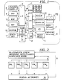
- Figure 1 shows a block circuit diagram of the postage meter machine of the invention, having a printer module 1 for a fully electronically produced franking image that contains an advertising slogan and/or a mark for a security imprint, at least one input unit 2 having actuation elements, for entering data and instructions and a display unit 3.
- the input unit 2 and the display unit 3 are connected to an input/output control module 4, having a non-volatile memory 5 for at least the constant parts of the franking image.
- the postage meter machine also includes a control unit 6.
- a character memory 9 supplies the necessary printing data for the volatile main memory module 7.
- the control unit 6 is a microprocessor ( ⁇ P) that is in communication with the input/output control module 4, the character memory 9, the volatile main memory module 7 the non-volatile main memory 5, a cost center memory 10, a program memory 11, a conveyor or feeder unit 12, potentially with a tape trigger, an encoder (coding disc) 13, as well as with a clock/data module 8 that is in constant operation.
- ⁇ P microprocessor
- Another method for improving the security of postage meter machines according to German Patent Application P 43 44 476.8 is based on the consideration of making the counterfeiting of data stored in the postage meter machine so difficult that the outlay is no longer worth the effort for a manipulator.
- a sensor 21 having a detector 20 can be connected to the input/output control module 4 of the postage meter machine in conjunction with this method--in the way shown in FIG. 1.
- a corresponding security means can be provided directly at the microprocessor or within the microprocessor--in a way that is not shown in FIG. 1.
- the preferred arrangement for generating a security imprint for postage meter machines includes a first memory area A (among other things, for the data of the constant parts of the franking format, including the advertising slogan frame) in the program memory 11.
- a cost center number is usually entered in order, among other things, to thus select the advertising slogan.
- An advantageous method for user-orientated accounting can be adopted in accordance with the invention wherein the selected slogan is examined in order to automatically identify the cost center which is to be billed.
- All alphanumerical characters or symbols are deposited pixel-by-pixel as binary data in the character memory 9.
- Data for alphanumerical characters or symbols are stored compressed, in the form of a hexadecimal number in the non-volatile main memory 5.
- the compressed data from the program memory are converted with the assistance of the character memory 9 into a print format having binary pixel data, the print format being stored in the volatile main memory module 7 in such a decompressed form.
- the compressed data are read from the main memory 5 and are converted with the assistance of the character memory 9 into a print format having binary pixel data, this being likewise stored in the volatile main memory module 7 in such a decompressed form.
- main memories 7a and 7b and pixel memory 7c are in communication with the printer module 1 via a printer control 14 having a print register 15 and output logic.
- the pixel memory 7c has an output side connected to a first input of the printer control 14, which has further control inputs to which output signals of the microprocessor control unit 6 are supplied.
- the constant parts of the franking format and advertising slogan are available, constantly decoded, in the pixel memory area I in the volatile pixel memory 7c.
- a second memory area B is present in the non-volatile main memory 5.
- the pixel memory area I in the pixel memory 7c is likewise provided for the selected, decompressed data of the variable parts of the franking format which are identified with the index j.
- the second pixel memory area II in the pixel memory 7c is provided for the selected, decompressed data of the variable parts of the franking format which are identified with the index k.
- a method and an arrangement for fast generation of a security imprint with only one microprocessor and one printer module in a postage meter machine are disclosed in European Application 576 113.
- the embedding of the print data of the mark information into the other print data preferably ensues during the printing of the respective column.
- the fully electronically generated print format makes it possible to embed the variable data of the mark into one or more windows within a fixed frame established by the postage meter machine print format during the column-by-column printing.
- a critical reason why the printing speed is not reduced by the required time for forming the mark data is the exploitation of a time reserve during printing by the microprocessor control unit 6 that implements the column-by-column embedding of window data.
- the memory areas B through ST in the non-volatile main memory 5 can contain a plurality of sub-memory areas in which the respective data are present, stored in datasets.
- the number chains (strings) that are entered for generating the input data with a keyboard 2, or via an electronic scale 22 that is connected to the input/output unit 4 and which calculates the postage fee, are automatically stored in the memory area ST of the non-volatile main memory 5.
- Data sets of the sub-memory areas, for example Bj, C, etc. are also preserved.
- the respective, selected, common frame data for the advertising slogan stamp, for the postmark and for the postage stamp are transferred from the non-volatile program memory 11 into the registers 100, 110, 120 of the volatile main memory 7a.
- the control code is decoded during the transfer and is stored in a separate memory area of the main memory area 7b.
- the respective, selected window data are loaded into the registers 200, 210, 220
- the registers are formed by sub-memory areas in the memory area of the main memory 7a.
- these aforementioned registers are a component of the microprocessor control unit 6.
- the run-length-coded hexadecimal data are converted into corresponding, binary pixel data by decompression (expansion).
- FIG. 1 shows a block circuit diagram of such a first version of the invention.
- the chronologically less variable (semi-variable) window data are subsequently referred to below as window data of type 1.
- the constantly changing (variable) window data are referred to below as window data of type 2.
- New frame and/or window data of type 1 can be selected as long as there is a need for that type of data after the insertion and storing of binary pixel data into the first pixel memory area I.
- an automatic generation of window data of type 2 follows with subsequent decompression as well as the entry thereof into the second pixel memory area II as binary pixel data.
- the aforementioned steps can be repeated if there is still not yet a print request.
- the combining with the other binary pixel data stored in the pixel memory area I preferably ensues after the presence of a print request during a printing routine.
- the data in the memory areas C, D and E can be modified with the input unit 2 and with the control unit 6.
- the same microprocessor of the control unit 6 that also implements the debiting routine and the printing routine is preferably utilized.
- the data from the memory areas are thereby composed during printing to form an overall presentation of a security imprint according to a previously defined allocation (freely selectable within certain limits).
- fourth and fifth memory areas D and E of the non-volatile main memory 5 can be used for this purpose.
- a name is stored in the fourth memory area B of the non-volatile memory 5, this name identifying the currently set frame of an advertising imprint, whereas data for a further, selectable allocation of at least one advertising imprint part to a frame of the advertising imprint corresponding to the aforementioned name are stored in a fifth memory area E. It is provided that the data from the memory areas are composed during printing to form an overall presentation of a security imprint corresponding to a previously defined allocation (freely selectable within certain limits).
- the identification of a postage meter machine generally ensues with an 8-place serial number which, however, need only partially enter into the mark symbol sequence in order to enable a check of the serial number printed in clear text. In a simple version, for example, this can be the checksum of the serial number. In more complicated, other versions, other data also enter into forming what is preferably at least a 2-place number that allows the checking of the serial number.
- an identification of postal matter on the basis of a mark generated with a cryptographic number can be undertaken for enabling an identification of postage meter machine without difficulties.
- the multi-place cryptographic number is not formed using the data values of the entire label stored as a hexadecimal number, but is formed and intermediately stored only using selected data values of the label frame and further data such as the machine parameters of the value setting and of the date.
- numeral or numerical values such as the number of the advertising slogan, but also data values of the image information can be utilized in the method of the invention to form the encoded information.
- any arbitrary region of the advertising slogan to which separate data are allocated in a data set can be utilized for the formation of the cryptographic number. To this end, individual data are selected from this data set.
- the run-length-coded hexadecimal data residing at the first location of the data set can be preferably employed.
- the data of the column-by-column, regional image information are selected from the data set dependent on a quantity that is present and/or generated in the machine, particularly by the current date, in order to take at least a number of data (hexadecimal numbers).
- a plurality of data sets can also be allocated to each advertising slogan number, each data set comprising those data pertaining to a subregion of the advertising slogan.
- the data set having the appertaining data of the column-by-column, regional image information is thereby selected dependent on a quantity present and/or generated in the machine in order to take at least a number of data (hexadecimal numbers).
- Those run-length-coded hexadecimal data corresponding to a predetermined printing column are preferably combined and encoded together with at least some of the data of the machine parameters (serial number, monotonously variable quantity, time data, inspection data such as, for example, the number of imprints at the last inspection, or a variable measuring the "suspiciousness" of the machine) and of the postage value.
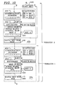
- the data are combined and encoded to form a number in a specific way set forth in conjunction with Figure 10.
- the DES algorithm data encryption standard
- a conversion into a specific graphic character set can be applied for a high security standard.
- the encoding of a combination number comprising a first, third and fourth number suffices in a data set that is 8 bytes long.
- a conversion of a cryptographic number into an identifier comprising symbols is undertaken by the character memory 9.
- a list that allocates graphic symbols to the individual cryptographic numbers and is selected by a further quantity, such as by the postage fee, is employed.
- the encoded, hexadecimal data are thereby decompressed in the character memory in order to print the identifier formed of the symbols to be printed.
- This is also a machine-readable mark.
- Other encoding methods and methods for converting the cryptographic number into a mark or identifier are likewise suitable. It is especially advantageous when the window data of type 2 for the security marks are accommodated in a separate window in the postage fee stamp or in the postmark or between the two stamps. The entire franking imprint is thus not enlarged (which is also not postally permitted), and an additional printer that prints at a different location of the letter is not required.
- encoded mark data deposited in a memory area F can be additionally utilized for identification--for example, of the postage meter machine serial number.
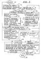
- a further possibility is to produce machine-readable version of the postage meter machine serial number that is printed unencoded as a barcode, the data thereof being taken either from the memory area F of the non-volatile main memory 5 or from the program memory 11 in order to insert the data into the franking image--as shown, for example, with reference to Figure 3e.
- An identification of the sender address, applied with a separate printer in the form of a barcode can be encouraged by offering a rebate for doing so.
- these aforementioned inclusions in the printed imprint can reduce the outlay for checking mailings because they allow a directed, machine check of specific senders, or of their postage meter machines.
- the central data station identifies suspicious postage meter machines and communicates the serial numbers to the postal authority, or to an institution commissioned to carry out a check.
- Newer postage meter machines are loaded with a new, reloaded credit with a telesetting FWV by a central data station.
- the central data station stores the credit amounts and the times at which these credits were transferred to the postage meter machine. Further security checks for checking the proper use of the postage meter machine are possible on the basis of these data stored in the central data station.
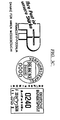
- Figure 2 shows the communication required in an evaluation of the security imprint of the invention. First, a data connection line L is required for reloading credits.
- the central data station receives information about the respective postage meter machine on the occasion of every communication via the data connection line L.
- the central data station sets up a data connection, as necessary, via a line H to the post office, or to the institution authorized to evaluate the franking stamps of the mailings.
- a check of the mailings is initiated by the postal authority, assuming that a postage meter machine is considered suspicious.
- the postal authority receives the information from the central data station via the data connection line H together with the serial number.
- the data connection line H is also used for inquires on the part of the post office dependent on the type of evaluation.
- the data connection line L is provided for inquiries from the postage meter machine to the central data station.
- the central data station calculates an average postage use Pk on the basis of the user-associated, historical data of a specific time period in the past.
- the inventive method presumes that the average credit influx corresponds to the average credit outflow, i.e. to the average postage use. This is expressed as the ratio of the sum of the credits G transferred in the time period under consideration and the sum of the time periods t lying between the reloadings:
- t K,n+1 G K,n P K • (1 + 1/ ⁇ )
- (1 + 1/ ⁇ ) serves the purpose of compensating normal fluctuations of the postage use.
- the postage meter machine can communicate the following register values to the central data station before a credit reloading:
- a value R2 taken from the ascending register corresponds to the interrogated value.
- the disposition factor ⁇ x is dependent on the classification of the postage meter machine user as an A, B or C customer. On the basis of the average postage use P K calculated for the user K, the disposition factor ⁇ K is allocated to one of, for example, three use categories A, B and C: P K ⁇ P A/B ⁇ ⁇ A P A/B ⁇ P K ⁇ P B/C ⁇ ⁇ B P K > P B/C ⁇ ⁇ C
- a typical disposition factor ⁇ A , ⁇ B , ⁇ C is allocated to each of these use categories, in accord wherewith the longest time (t A ) per time interval is reached according to equation (6) in the use category A, i.e. the category having the lowest use, and the shortest time (t C ) is reached in use category C.
- a simplification of this calculation strategy can be achieved if the individual quantities ⁇ K and t K,n+1 are not newly calculated for each user K, but a classification is undertaken instead.
- this user K On the basis of the average postage use P K calculated for the user K, this user K is classified into one of, for example, three use categories A, B and C.
- Each of these use categories has a typical use time t A , t B , t C allocated to it, whereby the use category A, i.e.
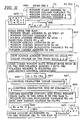
- the imprint of an arbitrarily selected postal item is checked for manipulation. After the acquisition of all symbols of a symbol sequence and the conversion thereof into data, their decoding can be undertaken with the corresponding DES key.
- the KOMBI number is then present as a result thereof, with the quantities, particularly the sum of all franking values and the current postage value being separated therefrom.
- the separated quantity of postage value G3 is compared to the postage value G3' actually imprinted.
- the quantity G4 that has been separated out i.e. the aggregate value of all franking values undertaken since the last reloading, is subjected to a monotony test on the basis of data of the most recently acquired quantity G4'.
- a difference amounting to at least the amount of the postage value must be present between the quantity G4 actually co-printed encoded in the mark and the most recently acquired quantity G4'.
- the most recently acquired quantity G4' is the aggregate value of all previously undertaken frankings that is stored in the central data station at the most recent remote interrogation of the register readings.
- the falsification of the postage meter machine serial number can likewise be recognized with the mark by separating the quantity G0 from the combination number after the decoding and checking the separated quantity G0 in a similar manner.
- the serial number of the postage meter machine which is co-printed can serve this purpose, from which an identification of the sender can be made, or, if present, the sender printed in clear text on the envelope can serve this purpose.
- the letter can be legally opened for identifying the sender.
- the postage meter machine accumulates the used postage values since the last credit reloading, or forms a remaining value, by subtracting the sum of the used postage values from the credit previously reloaded. This value is updated with every franking, and is combined in common with other security-relevant data (postage value, date, postage meter machine serial number), encrypted for protection against falsification, and finally is printed in the above-described way.
- the value W is compared to a fixed threshold that cannot be upwardly transgressed given normal use of the postage meter machine. A basis for considering the machine suspicious exists given an upper transgression.
- the postage value W is compared to a threshold SWn that corresponds to the respective postage use category.
- These postage use categories can be defined once for the use of the respective postage meter machine, however, they can also be derived from statistics kept for each postage meter machine. The statistics can be managed by the inspecting postal authority, or the statistical data can be used which the central data station produces anyway, and that are then transmitted to the postal authority.
- a further sophistication in the check is achieved according to a first version of the mark information, wherein the date of the last credit reloading t L is also contained as a second number in the combination number and is co-printed with the other data in encrypted form.
- the postal authority is then able to also check to what extent certain defined, maximum time intervals between two credit reloading have been exceeded, as a result of which the postage meter machine became suspicious.
- the date/time data for a monotonously, steadily increasing quantity can be used in another version of the mark information. So that additional space for imprinting the date of the last credit reloading is not required in the security imprint, these data can be combined with the absolute time count in this version. This latter is required in order to recognize forgeries in the form of copies with a monotony check according to a first evaluation version set forth in Figure 4c.
- the time data are then composed of two components:
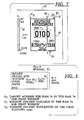
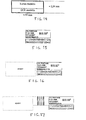
- the mark field is arranged under or in a field of the postage meter machine stamp and a row of such symbols is printed under the franking stamp imprint simultaneously therewith.
- the mark field can also be differently arranged, whereby appropriate conveyor devices for the postal matter are respectively provided when the CCD line camera is stationary.
- a mark reader 24 shown in Figure 4b can also be fashioned as a data pen guided in a guide.
- the apparatus includes a CCD line camera 241, a comparator 242 connected to the CCD line camera 241 and to a D/A converter, and an encoder 244 for acquiring the step-by-step motion.
- the data input of the D/A converter 243 for digital data and the outputs of the comparator 242 and encoder 244 are connected to an input/output unit 245. This is a standard interface to the input means 25 of the security imprint evaluation unit 29.
- the machine identification of the symbols in the identifier can ensue in two versions:
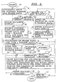
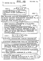
- the security imprint evaluation method of Figure 4d shows how the security information printed in the franking field is advantageously evaluated. It is necessary to enter individual quantities manually and/or automatically.
- the symbol row is vertically arranged between the value stamp and the postmark. In encrypted form, it contains information about the printed postage value, a monotonously variable quantity (for example, the date or an absolute time count), and the information related to the serial number or whether the suspicious mode is present. This information is visually/manually or automatically acquired together with the clear text information.
- a first evaluation version according to Figure 4d recovers the individual information from the printed mark and compares this to the information openly printed on the postal matter.
- the symbol row acquired in step 71 is converted into a corresponding cryptonumber in step 72.
- This unambiguous (unique) allocation can ensue via a table stored in the memory of the evaluation apparatus, whereby the symbol set in Figure 3f is especially advantageously used, in which case one digit of the cryptonumber then corresponds to each symbol field.
- the cryptonumber calculated in this way is decrypted in step 73 with the assistance of the cryptokey stored in the evaluation apparatus. If the cryptonumbers for the mark were generated according to a symmetrical algorithm (for example, the DES algorithm), then the initial number can again be generated from each cryptonumber according to step 73 of the first evaluation version.
- the initial number is a combination number KOZ and contains the numerical combination of at least two quantities, whereby the one quantity is represented by the upper places of the combination number KOZ and the other quantity is represented by the lower places of the KOZ. That part of the number combination (for example, the postal value) that is to be evaluated is separated and displayed in step 74. Each place of the initial number obtained after the decryptification has a content significance allocated to it. The information relevant for the further evaluation can thus be separated. When not manipulated the postage value to be actually checked, will form a monotonously, steadily variable quantity which, among other things, is critical. A specific, monotonously, steadily variable quantity and further quantities form specific mark information versions.
- the aggregate value of frankings stored in a postage meter machine register forms at least one first number allocated to the predetermined places of the combination number in a first mark information version.
- This aforementioned first number is a monotonously, steadily variable quantity.
- the mark changes at every imprint, making such a franked mailing unmistakable and simultaneously supplying information about the prior credit use.
- This information about the credit use is checked for its plausibility at time intervals on the basis of known credit use and credit reloading data stored in the central data station.
- the aggregate value of postage values since the last reloading date preferably forms at least one first number allocated to the predetermined places of the combination number.
- the second number that is placed at predetermined places of the combination number is formed, for example, by the last reloading date.
- this aforementioned first number corresponding to the aggregate value of frankings forms a monotonously, steadily variable quantity together with the second number directed to the credit reloading data at the time of the last reloading.
- this aforementioned first number corresponding to the aggregate value of frankings forms a monotonously, steadily variable quantity together with the second number relating to the item number data at the time of the last reloading.
- a corresponding number of alternative versions arises when the remaining value is used for the formation of the mark information instead of the aggregate value of frankings (used postage values since the last credit reloading). The remaining value is derived by subtracting the sum of used postage values from the previously loaded credit.
- a corresponding number of further alternative versions is achieved when momentary date/time data overall or since the last reloading date, item number data overall or since the last loading date, or other physical but chronologically determined data (for example, battery voltage) are involved in the formation of the mark information.
- the momentary date/time data form a monotonously, steadily variable quantity for a monotony variable MV v which is separated from the combination number in step 74.
- the evaluation version then includes the following steps:
- Quantities such as G1 and potentially G4 that may not be derivable from the stamped image of the postage meter machine, and at least one quantity G5 known only to the manufacturer of the postage meter machine and/or to the central data station and communicated to the postal authority, can also be encoded. These are likewise recovered from the mark by the decoding and can then be compared to the quantities stored for particular users.
- the lists stored in the memory 28 can be updated via a connection to the central data station 21.
- the lists produced for every serial number or every user and preferably stored in data banks of the data center for all postage meter machines contain data values for each variable, which are employed for checking the authenticity of a frankings.
- the allocation of the symbols to listed significances can be differently defined for different users.
- the advantage of an employed symbol set of the recited type is that, dependent on the demands of the respective national postal authority, an identification of an authentic franking stamp via the conceptual content of the symbol is enabled by machine (by, for example integral measurement of the degree of blackening of the symbols) and/or manually in a simple way.
- quantities G0, G2, G3 and G4 that are present unencoded in clear text are entered into the evaluation unit 29 by the user either manually or automatically with a reader in order then to derive, first, a cryptonumber and, thereafter, a mark symbol row with the same key and encoding algorithm as are employed in the postage meter machine.
- step 45 shown in Figure 10 a formation of newly coded window data of "type 2" for a mark image is formed.
- a mark generated therefrom is displayed and is compared by the operator to the mark printed on the postal matter (envelope). The symbolic nature of the marks displayed in the output unit 25 and printed on the postal matter accommodate the comparison to be undertaken by the operator.
- a trained inspector enters the graphic symbols in sequence into the input unit 25 either manually or automatically with a suitable reader 24 in a first step in order to transform the mark printed on the postal matter (letter) back into at least one first cryptonumber KRZ 1.
- the actuation elements, particularly the keyboard, of the input unit 25 can be identified with the symbols in order to facilitate the manual entry.
- the quantities that are openly printed and can be derived from the postage meter machine stamp particularly G0 for the serial number SN of the postage meter machine, G1 for the advertising slogan frame number WRN, G2 for the date DAT and G3 for the postal value PV, G4 for non-repeating time data ZEIT as well as at least one quantity G5 INS known only to the manufacturer of the postage meter machine and/or to the data center and communicated to the postal authority,are at least partially employed in order to form at least one comparative cryptonumber VKRZ1.
- the first quantity G1 is the advertising slogan frame number WRN that the inspector recognizes from the postage meter stamp. In addition to being known to the user, this first quantity is also known to the manufacturer of the postage meter machine and/or to the data center and is communicated to the postal authority.
- the advertising slogan frames WR n belonging to the serial number SN of the respective postage meter machine are displayed on a picture screen on the data output unit 27 together with allocated numbers WRN n .
- the inspector undertakes the comparison with the advertising slogan frame WR b employed on the latter, entering the number WRN n identified in this way.
- the stored lists transmitted from the central data station into the memory 28 contain, first, the current allocation of the parts of the advertising slogan frame WRNT to a second quantity G2 (for example, the date DAT) and, second, contain the allocation of symbol lists to a third quantity G3 (for example, the postage value PW).
- a list of parts SNT of the serial number SN selected by the first quantity G1, particularly the advertising slogan frame number WRN, can be present.
- User-associated information such as, for example, the advertising slogan frame number WRN, can be utilized for a manual, spot check evaluation of the mark because the decoder lists are selectable dependent on the user-associated information, these decoder lists containing corresponding data sets. That byte which is employed in generating the combination number is then identified from the data set with the quantity G2 (DAT).
- DAT data set with the quantity G2
- a monotony test is employed, first, for checking the uniqueness of the imprint. The inspector takes the serial number SN from the windows FE2 and FE3 of the imprint and identifies the user of the postage meter machine.
- the advertising slogan number can thereby be additionally employed, since this is usually allocated to specific cost centers when one and the same machine is used by different users.
- Data from the last examination also including data from the last inspection, are entered into the aforementioned lists. For example, such data are the item count if the machine has an absolute item counter available, or the absolute time data if the machine has such an absolute time counter available.
- the correctness of the printed postage value is checked in the first inspection step in conformity with the valid stipulations of the postal authority. Subsequent manipulations at the value imprint undertaken with fraudulent intent can thus be identified.
- the monotony of the data particularly of those in the window FR8, is checked. Copies of a franking stamp can thus be identified.
- a manipulation for the purpose of forgery is therefore not likely since these data are additionally printed in at least one mark field in the form of an encrypted symbol row.
- the number that is indicated in the window FE8 must have incremented in the imprint since the last inspection.
- Nine digits are presented in the window FE8, allowing the presentation of a time span of approximately thirty years with a resolution of seconds. The counter would overflow only after this time.
- These quantities can be recovered from the mark in order to compare them to the unencoded quantities printed openly.
- the other quantities particularly the serial number SN of the postage meter machine, and possibly the cost center of the user, can be checked and identified when a manipulation is suspected.
- the information such as the advertising slogan frame number WRN can be recited by a predetermined window FR9.
- the relevant window data are type 1, i.e. they vary less frequently than window data of type 2 such as, for example, the time data in the window FE8 and the mark data in the window FE6.
- the data of the windows FE8 and FE9 are not openly printed unencoded but are only employed for encoding.
- the windows FE8 and FE9 shown in Figure 3a are therefore absent from the postage meter machine print formats shown in Figures 3b through 3e in order to illustrate this version.
- the temporarily variable quantities to be entered for example the advertising slogan frame number WRN, the date DAT, the postage valve PW, time data ZEIT and the serial number SN, are automatically respectively detected from the corresponding field of the postage meter machine stamp with a reader 24 and are read in. It is therefore necessary that the arrangement of the windows in the postage meter machine imprint is thereby to be maintained in a predetermined way.
- the quantity G1 corresponds to an advertising slogan frame number.
- Corresponding numerical chains (strings) for window or frame input data are stored in the sub-memory areas ST i , ST j of the main memory 5 of the postage meter machine.
- the window data stored in the sub-memory areas ST j of the main memory 5 of the postage meter machine correspond to the quantities G0, G2 and G3, whereas the quantity G0 in the windows FE2 and FE3 is derived from the sub-memory areas T 2 and T 3 , the quantity G2 in the window FE4 is derived from the sub-memory area T 4 , and the quantity G3 in the window FE1 is derived from the sub-memory area ST 1 .
- the stored window data for an advertising slogan text part, a mark field, and possibly for a reference field are present in the sub-memory areas B 5 , B 6 and B 7 of the main memory 5 of the postage meter machine, which contains B k sub-areas. It should be noted that the window data are more frequently written into and/or read out from some of the sub-memory areas of the main memory 5 of the postage meter machine than others.
- the non-volatile main memory is an EEPROM
- a special memory method can be employed in order to be sure to remain below the limit number of memory cycles that is permitted for such memories.
- a battery-supported RAM can also be employed for the non-volatile main memory 5.
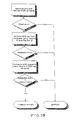
- Figure 5 shows a flow chart of the solution of the invention based on the presence of two pixel memory areas shown in Figure 1.
- decoded binary frame and window data are stored in two pixel memory areas before printing.
- the semi-variable window data of type 1 that are not to be frequently modified, such as date, serial number of the postage meter machine, and the slogan text part selected for a plurality of imprints, can be decompressed into binary data together with the frame data before printing and can be composed to form a pixel image stored in the pixel memory are I.
- constantly changing variable window data of type 2 are decompressed and are stored in the second pixel memory area II as binary window data before printing.
- Window data of type 2 are the printable postage value, dependent on postal matter and delivery, and/or the constantly changing mark.
- the binary pixel data from the pixel memory areas I and II are combined to form a print column control signal during the course of a printing routine during the printing of each column of the print format.
- a postage meter machine can run through several statuses (communication mode, test mode, franking mode and similar modes), this being disclosed in greater detail in German Patent Application 43 44 476.8, and in German OS 42 17 830.
- step 40 of the franking mode After the start step 40 of the franking mode, an automatic input of the most recent, currently stored window and frame data ensues on the basis of the input of the cost center in step 41 and a corresponding display ensues in step 42.
- Relevant memory areas C, D, E of the non-volatile main memory 5 are also interrogated with respect to an allocation of window and frame data or cost center that has been set. According to the aforementioned method or in another method disclosed, for example, in German OS 42 21 270, an advertising text part that is allocated to a specific advertising imprint can also be automatically prescribed.
- step 43 frame data are transferred into registers 100, 110, 120,... of the volatile main memory 7a and the control code is thereby detected and is stored in the volatile main memory 7b.
- the remaining frame data are decompressed and are stored in the volatile pixel memory 7c as binary pixel data.
- the window data are loaded into registers 200, 210, 220,... of the volatile main memory 7a and the control code is thereby detected and stored in the volatile main memory 7b, and the remaining window data are correspondingly stored column-by-column in the volatile pixel memory 7c after they are decompressed.
- the decoding of the control code, decompressing, and the loading of the fixed frame data as well as the formation and storing of the window identifiers are shown in detail in Figure 9a.
- step 44 either the decompressed frame and window data of type 1 are stored as binary pixel data in the pixel memory are I and can be further-processed in step 45 or a re-entry of frame and/or window ensues. In the latter instance, a branch is made to step 51.
- step 51 the microprocessor determines whether an input has ensued via the input unit 2 in order to replace window data, for example for the postage value, with new window data or in order to replace or to edit window data, for example for a slogan text line.
- step 52 the required sub-steps for the inputs are implemented in step 52, i.e. a complete, other data set is selected (slogan text parts) and/or a new data set is produced that contains the data for the individual characters (numerals and/or letters) of the input quantity.
- step 53 corresponding data sets are called in for a display for checking the input data and are offered for the following step 54 for reloading the pixel memory are I with the window data of type 1.
- the step 54 for embedding decompressed, variable window data of type 1 into the decompressed frame data following a re-entry or following the editing of these window data of type 1 is shown in detail in Figure 9c.
- step 51 the data of data sets called in according to the input are evaluated in order to detect a control code for a "color change", or for a "column end", which are required for an embedding of the newly entered window data. Those data that are not a control code are then decompressed into binary window pixel data and are embedded column-by-column into the pixel memory area I.
- step 51 it is found in step 51 that no window data are to be selected or edited, then a branch is made to step 55.
- step 55 the possibility for changing the fixed advertising slogan or frame data leads to a step 56 in order to implement the entry of the currently selected frame data sets together with the window data sets. Otherwise, a branch is made to step 44.
- step 44 When a new entry of selected, specific quantities is to ensue, a flag is set in step 44 and is taken into consideration in the following step 45 for the formation of data for a new mark symbol sequence, in case a step 45b is to be run according to a second version.
- step 45 a formation of the newly coded window data of type 2 ensues.
- the mark data for a window FE6 are generated here, with preceding steps of encoding data for producing a cryptonumber being included.
- a shaping as a barcode and/or symbol chain is also provided in this step 45.
- the formation of newly coded window data of type 2 for a mark image is set forth in two versions with reference to Figure 10.
- a monotonously variable quantity is processed in a step 45a, so that, ultimately, every imprint becomes unique due to the printed mark symbol sequence.
- other quantities are also processed in a step 45b preceding the step 45a.
- the correspondingly formed data set for the mark data is subsequently loaded in a region F and/or at least in sub-memory B 6 of the non-volatile main memory 5 and thereby overwrites the previously stored data set for which window characteristics were calculated or were predetermined and which are only now entered into the volatile main memory 7b.
- the sub-memory B 10 is preferably provided for a data set that leads to the printing of a second mark symbol sequence, as shown in Figures 3c and 3d.
- double symbol sequences can be printed next to one another in a way that is not shown in Figure 3b.
- the area F is preferably provided for a data set that leads to the printing of a barcode, as shown in Figure 3e.
- a byte-by-byte transmission of the data of the data set for the mark ensues into registers of the volatile main memory 7a in step 46, as does a detection of the control characters "color change" and "column end” in order then to decode the remaining data of the data set and in order to load the decoded, binary window pixel data of type 2 into the pixel memory area II of the volatile main memory 7c.
- the decoding of control code and conversion into decompressed, binary window data of type 2 is shown in detail in Figure 11.
- Such window data of type 2 are particularly identified with the index k and relate to the data for the window FE6, possibly the window FE10 for mark data, and, possibly the window FE8 for the ZEIT data of the absolute time count.
- the time data represent a monotonously variable quantity since this data ascends time-dependent.
- Time data that are still initially BCD packed and are supplied from the clock/date module 8 are converted and arranged into a data set containing suitable ZEIT data and having run-length-coded hexadecimal data. They can now likewise be store in a memory area B 8 for window data FE8 of type 2 and/or can be immediately loaded column-by-column into registers 200 of the main memory 7a or into the print register 15 in step 46.
- step 47 a determination is made at to whether there is a print request, the routine may entered into a waiting loop if a print request has not yet ensued.
- the waiting loop is directly conducted back to the start of the step 47 in the way shown in Figures 5 or respectively 6.
- the waiting loop is conducted back to the start of the step 44 or 45.
- the printing routine shown in detail in Figure 12 and implemented in step 48 for the combining of print column data from the pixel memory areas I and II ensues during the loading of the print register 15.
- the print control 14 effects a printing of the loaded print column immediately after the loading of the printing register 15.
- step 50 a check is made in step 50 to determine whether all columns for a postage meter machine print format are printed, by comparing the running address Z to the stored end address Z end .
- a return is made to step 57. Otherwise, a branch is made back to step 48 in order to produce and print the next printing column, until the printing routine has been ended.
- a check is made in step 57 to determine whether further mailings are to be franked. If there are not further items, the franking is ended in step 60. Otherwise, the end of printing has not yet been reached and a return is made back to step 51.
- Figure 6 shows a fourth version of the inventive solution, wherein, deviating from the block circuit diagram of Figure 1, only one pixel memory area I is employed. Decoded, binary frame data and window data of type 1 are combined and stored before the printing in this pixel memory area I.
- the steps up to step 46, which is eliminated in this version according to Figure 6, and step 48, which is replaced by step 49, are identical. Essentially, the same sequence in the execution occurs up to step 46.
- the printing routine for the combination of data taken from a pixel memory area I and from the main memory areas is discussed in greater detail in connection with Figure 13.
- the constantly changing window data of type 2 are decompressed in step 49 during the printing of each column and are combined with the binary pixel data from the pixel memory area I to be printed column-by-column to form a print column control signal.
- Window data of type 2 for example, are the printable postage value dependent on postal matter and delivery, and/or the constant changing mark.
- An envelope 17 is moved under the printer module 1 of an electronic postage meter machine with the speed v in the direction of the arrow and is thereby printed column-by-column with the illustrated postal value character image laster-like, beginning in column s 1 .
- the printer module 1 has a printing ledge 16 having a row of printer elements d1 through d240.
- the ink jet or a thermal transfer printing principle for example the ETR printing principle (Electroresistive Thermal Transfer Ribbon) can be utilized for the printing.
- a column s f to be printed at the moment constitutes one column in a character image that is composed of colored printing dots and "non-colored" (absent) printing dots.
- Each printer element is capable of printing one colored printing dot; the "non-colored" printing dots are simply the absence of a dot at a given location.
- the first two printing dots in the printing column s f are colored in order to print the frame 18 of the postal value character image 30 Fifteen non-colored (i.e.
- control character "00" that effects a color change
- a control character "00" that effects a color change
- control characters have a value "00" for color change.
- 256 dots or more can thus be addressed with this principle.
- control code "00" for color change can be theoretically eliminated here since an entire printing column of 240 dots having an identical coloration can be completely defined with a single hexadecimal number "F0". Given only insignificant additional memory capacity, a color change can nonetheless also be meaningful given a plurality of windows in one column.
- a data set for the printing column s f arises in the form of which the following is an excerpt: ... "2", “0D”, "02”, “4F”, "F1”, “68”, “FE”, ... .
- control characters are detected from hexadecimal numbers "QQ" and are interpreted in a step 43.
- window characteristics Z j , T j , Y j or Z k , T k , Y k are also generated and are stored in the volatile memory RAM space 7b together with defined values for the starting address Z 0 , ending address Z end and the overall run length R, i.e. the number of binary data required per printing column.
- a maximum of thirteen windows can be called in and the starting addresses can be defined for the thirteen control characters "F1" through "FD".
- a starting address Z 6 can be calculated and stored as a window characteristic with "F6" for the window beginning of a window FE6 of type 2.
- Figure 8 shows an illustration of the window characteristics for a first window FE1 related to a pixel memory image and stored separately therefrom.
- the window starting address Z 1 is stored as a destination address
- the position of the window FE1 in the binary pixel image can be reconstructed at any time.
- Binary data converted from the registers 100 and 200 are read bit-by-bit into the volatile pixel memory RAM space 7c, with an address allocated to every bit.
- the window column run length T j ⁇ R is the overall run length of the printing column.
- the new address in the same line but in the next column can be generated from the addition with R.
- Figure 9a shows the decoding of the control code, decompression and loading of the fixed frame data, as well as the formation and storing of the window characteristics.
- a control code "color change" was thereby taken into consideration for producing extremely high-resolution printing.
- the source address H i for frame data is incremented and a color change is made so that the starting data byte is interpreted, for example, as colored, this later leading to correspondingly activated printer elements.
- the aforementioned byte which is a run length-coded hexadecimal number for frame data, is now transferred into a register 100 of the volatile memory 7a in sub-step 4313 from the corresponding area H i of the non-volatile memory 5 automatically selected by the cost center KST.
- Control characters are detected and a run length variable X is reset to 0.
- a control character "00" for a color change is recognized; after branch back onto the sub-step 4312, this leads to a color change, i.e. the next run length-coded hexadecimal number effects an inactivation of the printer elements corresponding to the run length.
- sub-step 4315 a determination is made in sub-step 4315 as to whether a control character "FF" for image and is present.
- a control character "FF” for image and is present.
- the point d according to Figures 5 or 6 is reached and the step 43 has been executed.
- a check is made in sub-step 4316 to determine whether a control character "FE” for a column end is present. If such a control character "FE” is recognized, the color flip flop FF1 is reset in sub-step 4319 and a branch is made to sub-step 4312 in order to then load the byte for the next printing column in sub-step 4313.
- sub-step 4317 determines whether a control character for a window of type 2 is present. If such a control character is recognized, a branch is made to sub-step 43222. Otherwise, a check is made in sub-step 4318 to determine whether a control character for windows of type 1 is present. If so, a point c 1 is reached at which a step 43b shown in Figure 9b is implemented. If no control character for type 1 window data is recognized in sub-step 4318, then the run length-coded frame data are present in the byte that has been called in.
- sub-step 4320 These data are decoded in sub-step 4320 and are converted into binary frame pixel data, and are stored in the pixel memory area I of the pixel memory 7c under the address Z that has been set.
- the column run length variable X is determined according to the number of converted bits, and subsequently the destination address for the pixel memory area I is raised by this variable X. A point b has thus been reached and a branch is made back to sub-step 4312 in order to call in a new byte. If a control character for type 2 window data were present in sub-step 4322, the executed storing of window characteristic T k is identified.
- the window column run variable T k in this case, is still at the initial value 0, the window starting address Z k corresponding to the address Z is identified in a sub-step 4323 and is stored in the volatile main memory 7b. Otherwise, a branch is made to sub-step 4324.
- the sub-step 4323 is likewise followed by the sub-step 4324 in which the window characteristic of the window column variable T k is incremented.
- the previous window column variable T k stored in the volatile main memory 7b is overwritten with the current value and the point b is reached.
- FIG. 9b shows the embedding of decompressed, current window data of type 1 into the decompressed frame data after the start of the postage meter machine, or the editing of frame data. Assuming that a control character for type 1 window was recognized in sub-step 4318, the point c 1 , and thus the beginning of step 43b, is reached.
- sub-step 4330 the executed storing of window characteristics T j is identified.
- the window column run variable T j in this case, is still at the initial value 0, the window starting address Z j corresponding to the address Z is identified in a sub-step 4331 and is stored in the volatile main memory 7b. Otherwise, a branch is made to a sub-step 4332.
- the sub-step 4331 is likewise followed by the sub-step 4332 in which the window characteristic of the window column run length T j and the window column run length variable W j are set to an initial value 0 and the window source address U j is set to the initial value U oj-1 , and the second color flip flop FF2 for windows is set to "print uncolored".
- the previous window source address U j is incremented and a color change is carried out, so that data forming window bytes that are loaded in the following sub-step 4334 are interpreted as colored, this subsequently leading to activated printer elements during the printing.
- a byte from the sub-memory areas B j in the non-volatile main memory 5 is loaded into registers 200 of the volatile main memory 7a and detection for control characters is carried out.
- the window column run length Y j is incremented by the value of the window column run length variable W j .
- a finding is made in sub-step 4336 to determine whether a control character "00" for color change is present.
- sub-step 4337 a check is made in sub-step 4337 to see whether a control character "FE" for end of column is present. If this is not the case, window data are present.
- the content of the register 200 is decoded with the assistance of the character memory 9 and the binary window pixel data corresponding to this byte are stored in the pixel memory area I of the pixel memory 7c.
- the window column run length variable W j is subsequently identified in order to increment the address Z by the value of the variable Wj.
- the new address for a byte of the data set to be newly converted is thus available and a branch is made back onto sub-step 4333 in which the new source address for a byte of the data set for window FEj is also generated. If a control character "FE" for an end of column was recognized in sub-step 4337, a branch is made to sub-step 4340 wherein the window column variable T j is incremented and the window column variable T j and the window column run length Y j stored in the volatile main memory 7b are overwritten with the current value. Subsequently, a color change is made in sub-step 4341 and point b has been reached.
- Step 43b has thus been executed and new frame data can be covered in step 43a in case a next window is not recognized or point d has not been reached.
- Figure 9c shows the embedding of decompressed, variable type 1 window data into the decompressed frame data after the editing of these type 1 window data.
- pixel memory data and window characteristics have already been stored before the beginning of step 54.
- the sub-step 5440 begins with the identification of that plurality n' of windows for which that data have been modified and with an identification of the relevant window start address Z j and window column variable T j for each window FEj.
- a window count variable q is also set to 0.
- a determination is made in sub-step 5441 as to whether the value of the window count variable q has already reached a value of the window change number n'. Given no changes, i.e. n' 0, the comparison is positive and the point d is reached. Otherwise, a branch is made to sub-step 5442, wherein the window start address Z j and the window column variable T j for a first window FEj whose data were modified are taken from the volatile main memory 6b. Moreover, the source address U j is set to an initial value U oj-1 , the destination address Z j is employed for addressing the pixel memory area I, and a window column counter P j and the second color flip flop FF1 are reset to the initial value of zero.
- the source address is incremented in the following sub-step 5443 and a color change is implemented before sub-step 5444 is reached.
- sub-step 5444 one byte of the modified data set in the non-volatile memory is called in and is transferred into the register 200 of the volatile memory 7a, and control characters are detected. Given a control character "00" for a color change, a branch is made in sub-step 5445 back to sub-step 5443. Otherwise, a branch is made to sub-step 5446 in order to search for control characters "FE" for a column end. If such a control character is not present, the content of the register 200 can be decoded in the following sub-step 5447 with the assistance of the character memory 9 and can be converted into binary pixel data for the window to be modified.
- All modification data for a first modified window would then be loaded into the pixel memory area I and a branch is made back to sub-step 5453, and from this sub-step 5453 to the sub-step 5441 in order to transmit modification data into the pixel memory area I for a possibly second window.
- the window count variable q is incremented for this purpose and the following window start address Z j+1 and the following window column variable T j+1 are identified.
- sub-step 5451 the destination address for the data in the pixel memory area I are incremented by the frame overall column length R for this purpose.
- the destination address D j is thus set to the next column for binary pixel data of the window in the pixel memory area I.
- sub-step 5452 the color flip flop is reset to 0, so that the conversion begins with pixel data interpreted as colored.
- Step 45a comprises further sub-steps shown in Figure 10 for forming a new, coded window data of type 2 for a mark image.
- binary pixel data that are already decompressed are present in the pixel memory area I
- the output data required for the data sets containing the compressed data for the windows FEj and possibly for the frame data are again requested in step 45 following step 44 in order to form new, coded window data of type 2 for a mark symbol sequence.
- the identical output data (or input data) are stored as a BCD-packed number in the memory areas ST w according to the respective quantities G w .
- the data sets are stored non-volatilely in the sub-memory areas A i and B j .
- the data for a data set for windows FEk of type 2 are not combined in a plurality of steps and are also non-volatilely stored in a sub-memory area B k .
- a method for fast generation of a security imprint includes a step 45a implemented by the microprocessor of the control unit 6 of the postage meter machine before a print request (step 47) and after an offering of quantities.
- the step 45a including the following sub-steps:
- a mark symbol sequence is generated in a step 45a.
- at least one part of the quantities is employed in the postage meter machine on the basis of the quantity of information forming the quantities G0 through G5.
- These quantities should only be partially openly printed unencoded in the postage meter machine imprint, in order to form a single numerical combination (sub-step 451) that is encrypted to form a single cryptonumber (sub-step 452), which is then converted into a mark to be printed on the postal matter (sub-step 453).
- the storing of the data set to be generated for the mark in a window FE6 can ensue in a concluding sub-step 454. Point c 3 has then been reached.
- the time that is otherwise required in the postage meter machine for generating further cryptonumbers can thus be saved by this first version implemented in sub-step 45a.
- the steadily, monotonously variable quantity G w is at least one ascending or descending machine parameter, particularly a time count or the complement thereof during the service life of the postage meter machine.
- the machine parameter be time-dependent, particularly a quantity G4a characterizing the decreasing battery voltage of the battery-supported memory, and comprises a second, steadily, monotonously decreasing quantity G4b or the respective complement of the quantity G4a and G4b.
- the second, steadily, monotonously decreasing quantity G4b is the complement of the item count or a steadily, monotonously decreasing time-dependent quantity.
- the steadily, monotonously decreasing quantity is a numerical value corresponding to the next inspection date (INS) and a steadily, monotonously decreasing time-dependent quantity.
- the steadily, monotonously increasing quantity includes the date or the item count identified at the last inspection.
- the control unit 6 for the formation of a third group of interrelated places of the combination number KOZ1.
- the upper ten places of the combination number KOZ1 are offered from the memory areas ST w in sub-step 451 for the ZEIT data (quantity G4) and the lower four places are offered for the postal value (quantity G3).
- a combination number having 14 digits thus arises; this is then encoded.
- a maximum of eight bytes, i.e. 16 digits, can be encoded at once.
- the combination number KOZ1 can thus be potentially supplemented by a further quantity in the direction of the less significant places.
- the supplementary part can be a part of the serial number SN or the number WRN of the advertising slogan frame, or can be the byte that is selected from the data set of the advertising slogan frame dependent on a further quantity.
- this combination number KOZ1 can be encoded into a cryptonumber KRZ1 in approximately 201ms, by means of a plurality of further, known steps sequence here.
- the cryptonumber KRZ1 is to be converted in sub-step 453 into a corresponding symbol sequence on the basis of a predetermined mark list stored in the memory areas M of the non-volatile main memory 5.
- inspection data for example, the date of the last inspection or the remainder of the serial number SN, or the serial number SN itself, and the byte of the data set of the advertising slogan frame that was not involved in the first combination number KOZ1, or selected, predetermined parts thereof.
- Respective rows having a total of 20 symbols are imaged in Figure 3 in windows FE6 and FE10 are arranged orthogonally relative to one another, with which, for example, the total of eight bytes, i.e. 16 digits of the cryptonumber KRZ1 and further information can be forwarded uncoded, or encoded in some other way.
- a second version including a step 45b in addition to the step 45a differs from the first version on the basis of different output or input quantities that, however, are to be identically taken into consideration.
- a mark symbol sequence is successfully generated in two steps 45b and 45a, whereby the step 45b is implemented analogously to the step 45a.
- a check is made to determine whether a flag was set in order to initiate the implementation of sub-steps 45b and/or 45a, a second combination number KOZ2 comprising at least the other part of the quantity G0, G1 characterizing the user of the postage meter machine is formed in the sub-step 45b, is subsequently encoded to form a second cryptonumber KRZ2, and is then converted into at least one second mark symbol sequence MSR2 on the basis of a second set SSYQ of symbols.
- a combination number KOZ2 is formed in sub-step 455, such as from the quantities of the remaining parts of the serial number SN, for advertising slogan (frame) number, and other quantities.
- a cryptonumber KOZ2 is formed in sub-step 456.
- the transformation into a mark symbol sequence then again ensues in sub-step 457, this being in intermediately stored in non-volatile fashion in sub-step 458.
- the step 45a comprising the sub-steps 451 through 453 is executed. This can potentially be terminated by a sub-step 454. Point c 3 is subsequently reached.
- a time-saving nonetheless arises due to an evaluation in a first sub-step 450 to determine whether the selected quantities required for the formation of the mark symbol sequence in sub-step 45b have been modified by an input. Given a re-input of selected, specific quantities, a flag would be set in step 44 and would be taken into consideration in a following formation of data for a new mark symbol sequence in order to execute step 45b. If, however, this is not the case, then a mark symbol sequence, or parts of the mark symbol sequence stored in a memory area 458 in non-volatile fashion and already formed earlier can then be accessed. In a modified embodiment, an encoding algorithm other than the DES is employed for saving time in sub-step 456.
- a transformation is undertaken in the sub-step 453 of the first version, or in the sub-step 457 of the second version, for additionally increasing the information density of the mark symbol sequence compared to the cryptonumber KRZ1 or KRZ2.
- a set of 22 symbols is now employed given an cryptonumber having 16 digits, in order to form the information with only 12 digits--in the way shown in Figure 3b.
- the mark symbol sequence shown in Figure 3b is to be doubled for two cryptonumbers. This can occur with a further mark symbol sequence that lies parallel to the mark symbol sequence shown in Figure 3b.
- it can also be shown that only a symbol set comprising 14 symbols is required for a mark symbol sequence having 14 digits.
- a mark symbol sequence as was shown in Figure 3a is designed for ten digits and can image a cryptonumber KRZ1 if the symbol set comprises forty symbols.
- a fully automated input and evaluation is preferable--if only to avoid subjective errors by the inspector in the recognition of the symbols.
- the data of a data set for the mark symbol sequence are then embedded into the remaining pixel data after they have been decompressed.
- two different possibilities are inventively provided for this purpose.
- One possibility shall be set forth in greater detail with reference to 11 and the other shall be set forth in greater detail with reference to Figure 13.
- Step 46 of Figure 5 is particularly set forth in Figure 11.
- a sub-step 4660 window characteristics Z k and T k are prescribed for modified window data, the window modification number p' is identified, and a window count variable q is set equal to 0.
- An evaluation is made in sub-step 4661 to determine whether the window count variable q is equal to the window modification number p'. The point d 3 and thus the next step 47 would then already have been reached. This loop, however, is usually not yet begun at the start since the monotonously ascending quantity constantly generates new mark symbol sequences for every imprint. Otherwise, if a modification has ensued, a branch is made to sub-step 4662 in order to enter window characteristics corresponding to the modified windows and in order to set initial conditions.
- a new source address for the data of the data set of the window FEk being processed at the moment is generated in order to load a byte of the coded window data of type 2 from the memory area B k into the register of the non-volatile memory 7a in the next sub-step 4664 and in order to detect control characters.
- the window column run length Y k is then incremented by the window column run length variable W k ; this is still zero here.
- a check is made for control characters for color change (sub-step 4666) and a branch is potentially made back to sub-step 4663 or a search is made for control characters indicating column end (sub-step 4667).
- sub-step 4669 Given a successful outcome of this search, a branch is made to sub-step 4669 and the window column counter P k is incremented. Otherwise, a decoding of the control code and a conversion of the called-in bytes into decompressed, binary window pixel data of type 2 are undertaken in the next sub-step 4668. A check is made in sub-step 4670 to determine if all columns of the window have been processed. When this is the case, a branch is made to sub-step 4671 and the column run length Y k of the window FEk is stored in the memory 7b and a branch is made back to sub-step 4673.
- sub-step 4670 If it is found in sub-step 4670 that all columns have not yet been processed, a branch is made back to sub-step 4663 via the sub-step 4672, whereby the window characteristic Y k and the color flip flop are reset to 0.
- next sub-step 4668 a decoding of the control code and a conversion of the called-in byte into decompressed, binary window pixel data of type 2 are undertaken again, if necessary.
- a branch is again made to sub-step 4661. When all modification windows have been processed, point d 3 has been reached.
- sub-step 471 The printing routine for the combination of data from the pixel memory areas I and II shown in Figure 12 sequences when a print request is recognized in step 47 and data have been loaded in a sub-step 471, which is not shown in Figure 5.
- the end address Z end is loaded
- the running address Z (running variable) is set to the value of the source address Z 0 in area I of the pixel memory area 7c
- the window column counted P k is set to the respective value corresponding to the stored window column variable T k
- the window bit count lengths X k are set to the respective value corresponding to the stored window column run length Y k
- the print column comprises N print elements. Subsequently, when the point e 1 is reached at the start of step 48, a number of sub-step sequence.
- the register 15 of the printer control 14 is serially loaded with binary print column data in a sub-step 481 bit-by-bit from the area I of the pixel memory area 7c, these binary print column data being called in with the address Z, and the widow counter h is set to a number that corresponds to the window number p incremented by one.
- a window counter h is decremented.
- This window counter h successively generates window numbers k, whereupon the address Z reached in the pixel memory is compared in the sub-step 483 to the window start address Z k of the window FE k .
- a branch is made to sub-step 489 which is in turn composed of the sub-steps 4891 through 4895. Otherwise, a branch is made to sub-step 484.
- sub-step 4891 a first bit from the area II of the pixel memory 7c for the window FE k and the binary window pixel data are serially loaded into the register 15, whereby the address Z and the bit count variable are incremented 1 in sub-step 4892 and the window bit count length X k is decremented.
- sub-step 4893 Further bits are loaded from the area II in a sub-step 4893 if all bits corresponding to the window column run length Y k have not yet been loaded. Otherwise, a branch is made to sub-step 4894, whereby the window start address Z k for the addressing of the next window column is correspondingly incremented by the overall length R and the window column counter P k is decremented. Simultaneously, the original window bit count length X k is restored corresponding to the window column run length Y k . A check is then carried out in sub-step 4895 to determine whether all window columns have been processed. When this is the case, the start address Z k for the corresponding window FE k is set to 0 or an address which lies outside the pixel memory area I.
- sub-step 484 A check is carried out in sub-step 484 to determine whether all window start addresses have been interrogated. When this has occurred, then a branch is made to sub-step 485 in order to increment the running address Z. When this has not yet ensued, a branch is made back to sub-step 481 in order to continue to decrement the window counter h until the next window start address is found or until the window counter h becomes equal to zero in sub-step 484.
- a check is carried out in sub-step 486 to determine whether all data for the column s k to be printed have been loaded in the register 15.
- bit count variable is incremented 1 in sub-step 488 in order to return to the point e 1 and in order then to load the next bit addressed with the address Z from the pixel memory area into the register 15 in the sub-step 481.
- the register 15 is full, then the column is printed in sub-step 487.
- a determination is subsequently made as to whether all pixel data of the pixel memory areas I and II have been printed out, i.e. the mailing has been completely franked. When this is the case, then point f 1 is reached. Otherwise, a branch is made to sub-step 501 and the bit count variable 1 is reset to 0 in order to subsequently to branch back to point e 1 .
- the next print column can now be produced.
- the printing routine for the combination of data taken from only one pixel memory area I and from main memory areas shall be set forth in greater detail with reference to Figure 13.
- a sub-step 471 immediately ensues, as already set forth in conjunction with Figure 12, in order to reach the point e 2 .
- the step 49 which now begins--which was already shown in Figure 6--includes the sub-steps 491 through 497 and the sub-step 4990 through 4999.
- a color change in the evaluation of the window pixel data of type 2 to be converted which was already set forth in conjunction with Figure 7 ensues here, so that the first hexadecimal data of the data set that is called in are evaluated, for example, as colored.
- the source address is incremented.
- sub-step 4994 A determination is made in sub-step 4994 as to whether a control code "column end" is present. If this is not yet the case, then the register content must be decoded, and thus must be compressed. A series of binary pixel data exists in the character memory 9 for each run time-coded hexadecimal numerical value; this series can correspondingly be called in on the basis of the hexadecimal number loaded in the volatile main memory 7a. This ensues in sub-step 4995, whereby the decompressed window pixel data for a column of the windows FE j of type 2 are subsequently serially loaded into the print register 15 of the printer control 14.
- sub-step 4996 the address is then incremented and a corresponding next hexadecimal number in the data set is selected, this being stored in the sub-area B 5 in the non-volatile main memory 5, and the bits converted in the decoding of the run length coding are identified in order to form a window column run length W j with which the destination address is incremented.
- the new destination address for the read-in has thus been generated and a branch can be undertaken back to sub-step 4991.
- sub-steps 4997 through 4999 follow in order subsequently to return to point e 2 .
- the sub-steps 4998 and 4999 sequence similar to the sub-steps 4895 and 4984 shown in Figure 12.
- sub-step 497 the completely loaded print column is printed.
- the sub-steps 491 through 497 sequence similar to the sub-steps 481 through 487 shown in Figure 12.
- a high printing speed is achieved with a plurality of variable print format data to be embedded into a stored, fixed print format.
- a printer module applies a franking image that is generated in a fully electronic way onto a mailing, in accord with the current inputs or, respectively, data actuated via an input means and an input/output control module, a display unit being capable of being checked therewith.
- the data for the constant parts of the franking image which relate at least to the frame of an advertising imprint, are stored in a first memory area A i of the program memory 11.
- the non-volatile memory 5 has a number of memory areas, and the data for the variable or semi-variable parts of the franking image are respectively stored in second memory areas B k or B j of the non-volatile memory 5.
- the names of the advertising imprint frames can be allocated to the selectable cost center numbers for the cost centers in a third memory area C of the non-volatile memory 5.
- Advertising imprint frame numbers WRN correspond to the names of the advertising imprint frames.
- the printed pattern is generated from fixed data and current data with the microprocessor-controlled printing process and the printer controller.
- Frame data are taken from the first memory area of the program memory 11, are decompressed and are stored in a first area I of a pixel memory 7C.
- Semi-variable window data from the second memory area B j are subsequently embedded into the aforementioned constant data.
- a debiting under the aforementioned cost center number is undertaken in a sub-step 470 in the cost center memory 10 in the case of a print request 47, and variable window data from the second memory area B k for the marking data are subsequently embedded during printing, whereby the embedding ensues during the loading of the print register 15.
- step 47 an advance is made to the step 48 or 49 containing a printing routine and, if a print request that has not yet ensued a wait ensues for the print request in a waiting loop by making a direct return to the start of step 47--in the way shown in FIGS. 5 or 6--.
- the postage meter machine of the invention has a further time advantage since cryptonumbers need not permanently be regenerated according to the DES algorithm. The next acquirable point in time after a generation of the row of marking symbols can already trigger the printing.
- An additional step 61 can chronologically precede the step 47 in order, given the identification of the absence of a print request in step 61, to cause a branch to a standby mode (step 62), for example in order to display the current time of day and/or date and/or in order to automatically implement error checks.
- a branch from the standby mode 62 is in turn made directly to the starting step 40 or indirectly via further steps or modes.
- the step 45 can be placed between the steps 53 and 54.
- step 54 following step 45 the data of a data set for the mark symbol sequence--after they are decompressed--are then embedded into the remaining pixel data of the pixel memory area I. A further pixel memory area is then not required.
- Another version only stores the frame pixel data in the pixel memory area and embeds all window pixel data immediately into the corresponding columns read into the print register 15 without requiring a pixel memory for window data in-between.
- the memory area A i can be foregone.
- the invariable image information is stored in a read-only memory, for example in the program memory 11. In the decoding of the invariable image information, this read-only memory 1 1 is accessed, so that the intermediate storage can be eliminated.
- the program memory 1 1 is connected to the control unit 6, with the data for the constant parts of the franking image that are directed at least to one advertising imprint frame being stored in a first memory area A i .
- An allocated name identifies the advertising imprint frame.
- the non-volatile main memory 5 is connected to the control unit 6, with the data for the semi-variable parts of the franking image being stored in the second memory area Bj and an allocated name identifies the semi-variable part.
- a first allocation of the names of the semi-variable parts to the names of the constant parts exists corresponding to the stored program.
- a second allocation is undertaken according to the cost center number stored in a third memory area C, so that an advertising imprint can be selectively allocated to each cost center KST.
- a microprocessor is provided in the control unit 6 in order to implement an encoding to form marking pixel image data before they are embedded column-by-column into the remaining pixel image data.
- a volatile main memory 7, a print controller 14 having a print register 15 are therefore connected to the microprocessor, with which the marking pixel image data are inserted into the remaining fixed and variable pixel image data during printing under the control of the microprocessor and corresponding to a program stored in the program memory 11.
- the indicium area will be subdivided into two parts, as shown in Figure 14. These include a human readable part, such as in an upper portion of the indicium, and an OCR (Optical Character Reader) readable area, such as in a lower part of the indicium.
- the human readable area of the indicium will contain the following items: # Information Type Example 1. Date of mailing numeric 11-21-1966 (MM-DD-YYY) 2. Postage numeric 00.32 5 3. Vendor ID alpha Francotyp-Postalia 4. Machine ID numeric 1234567 5. Originating ZIP alpha MERRIFIELD VA
- the OCR-readable portion will contain security data, such as OCR-readable digits, such as the following example: 11234567064841121 96003252222212345
- the OCR-readable area contains the following items: # Information count example lifetime 1. Vendor Id 1 1 constant 2. Device Id 7 1234567 constant 3. Origin ZIP 5 06484 constant 4. Date 6 112196 semiconstant 5. Postage Amount 5 00325 semiconstant 6. Piece Count 5 22222 variable 7. MAC 5 12345 variable Sum 34 As noted above, the OCR-readable area will occupy the lower portion of the indicium. For better machine readability, it is preferable to flank the OCR-readable area by lateral marking stripes, as shown in Figure 15 wherein the above-noted example of OCR-readable digits are shown in the lower portion of the indicium with vertical lines at each end thereof. Figure 15 also show more details of the information contained in the upper-human-readable area.
- Figure 16 shows a sample format of an imprint including three areas: The franking indicium (using the indicium of Figure 15 as an example), and advertising block ADVERT, and an FIM mark in between.
- the ink color is preferably black in order to achieve a higher scanning quality.
- the FIM mark is defined in the Domestic Mail Manual of the USPS as follows.
- the top of the FIM must be within 1/8 inch of the edge of the envelope, and may extend to the edge.
- the width of the entire FIM area shall be 1-1/4 inches (32 mm), and the height shall be 5/8 inch (15.9 mm).
- Figure 17 shows an example of an imprint format including only the franking indicium (again using the indicium of Figure 15 as an example) and an advertising block ADVERT.
- the ink is fluorescent and is preferably of a color other than red for better machine readability. Since black shades have a low fluorescent emittance, preferably blue or brown fluorescent ink is used in printing an imprint such as shown in Figure 17.
- MAC message authentication code
- a cryptographic data authentication algorithm DAA
- a data authentication code is generated by applying the DAA to data as described below. The DAC is a mathematical function of both the data and a cryptographic key.
- the DAA described herein uses the data encryption standard (DES) cryptographic algorithm specified in FIPS PUB 113 (Federal Information Processing Standards Publication).
- DES data encryption standard
- FIPS PUB 113 Federal Information Processing Standards Publication
- the DES algorithm transforms (or encrypts) 64-bit input vectors to 64-bit output vectors using a cryptographic key.
- D any 64-bit input vector
- O the 64-bit output vector
- O ENCRYPT (D)
- D ENCRYPT
- the data are authenticated by grouping the data into contiguous 64-bit blocks: D1, D2, ...Dn.
- the final block will be a partial block of data, left-justified with appended zeros so as to form a full 64-bit block.
- the DAC is selected from 0n, with the leftmost 16 bits of 0n being selected as the DAC.
- the cipher block chaining mode (CBC) with an initialization vector (IV) equal to zero yields the required DAC calculation.
- Figure 18 shows an example of DAC computation.
- the verification process includes the steps of reading the indicium and recovering the data in the OCR area, and, in a verification unit, extracting the vendor ID and the device ID, and performing a data base search to retrieve the associated DES key.
- the integrity of the data must then be verified.
- the DAC is generated using the current data, and is compared with the previously generated DAC found in the indicium. If the comparison result is positive, the integrity (i.e., the authenticity) of the data is verified.
- Figure 19 is a flowchart showing this OCR indicium verification.
Landscapes
- Physics & Mathematics (AREA)
- General Physics & Mathematics (AREA)
- Engineering & Computer Science (AREA)
- Computer Security & Cryptography (AREA)
- Theoretical Computer Science (AREA)
- Devices For Checking Fares Or Tickets At Control Points (AREA)
- Storage Device Security (AREA)
Applications Claiming Priority (2)
| Application Number | Priority Date | Filing Date | Title |
|---|---|---|---|
| US08/798,604 US5953426A (en) | 1997-02-11 | 1997-02-11 | Method and arrangement for generating and checking a security imprint |
| US798604 | 1997-02-11 |
Publications (2)
| Publication Number | Publication Date |
|---|---|
| EP0862143A2 true EP0862143A2 (de) | 1998-09-02 |
| EP0862143A3 EP0862143A3 (de) | 2000-09-13 |
Family
ID=25173825
Family Applications (1)
| Application Number | Title | Priority Date | Filing Date |
|---|---|---|---|
| EP98250018A Withdrawn EP0862143A3 (de) | 1997-02-11 | 1998-01-21 | Verfahren und Anordnung zur Erzeugung und Überprüfung eines Sicherheitsabdruckes |
Country Status (2)
| Country | Link |
|---|---|
| US (1) | US5953426A (de) |
| EP (1) | EP0862143A3 (de) |
Cited By (9)
| Publication number | Priority date | Publication date | Assignee | Title |
|---|---|---|---|---|
| EP1061479A2 (de) | 1999-06-15 | 2000-12-20 | Francotyp-Postalia AG & Co. | Anordnung und Verfahren zur Generierung eines Sicherheitsabdruckes |
| EP1067482A1 (de) * | 1999-07-05 | 2001-01-10 | Francotyp-Postalia Aktiengesellschaft & Co. | Druckbild |
| WO2002065409A3 (de) * | 2001-02-12 | 2003-08-07 | Deutsche Post Ag | Verfahren zur überprüfung der auf einer postsendung aufgebrachten freimachung |
| US6947483B2 (en) | 2000-08-18 | 2005-09-20 | Nortel Networks Limited | Method, apparatus, and system for managing data compression in a wireless network |
| EP1454259A4 (de) * | 2001-05-03 | 2007-03-28 | Pitney Bowes Inc | Verfahren zur berechnung von frankierungsstempeln für poststücke |
| US7280495B1 (en) | 2000-08-18 | 2007-10-09 | Nortel Networks Limited | Reliable broadcast protocol in a wireless local area network |
| US7308279B1 (en) | 2000-08-18 | 2007-12-11 | Nortel Networks Limited | Dynamic power level control on transmitted messages in a wireless LAN |
| US7339892B1 (en) | 2000-08-18 | 2008-03-04 | Nortel Networks Limited | System and method for dynamic control of data packet fragmentation threshold in a wireless network |
| US7366103B2 (en) | 2000-08-18 | 2008-04-29 | Nortel Networks Limited | Seamless roaming options in an IEEE 802.11 compliant network |
Families Citing this family (32)
| Publication number | Priority date | Publication date | Assignee | Title |
|---|---|---|---|---|
| US6345104B1 (en) | 1994-03-17 | 2002-02-05 | Digimarc Corporation | Digital watermarks and methods for security documents |
| NL1010616C2 (nl) * | 1998-11-20 | 2000-05-23 | Ptt Post Holdings Bv | Werkwijze en inrichtingen voor het afdrukken van een frankeerkenmerk op een document. |
| PT1131793E (pt) * | 1998-11-20 | 2006-09-29 | Ptt Post Holdings Bv | Metodo e sistema para produzir e verificar uma marca de franquia |
| US7162035B1 (en) | 2000-05-24 | 2007-01-09 | Tracer Detection Technology Corp. | Authentication method and system |
| US7152047B1 (en) | 2000-05-24 | 2006-12-19 | Esecure.Biz, Inc. | System and method for production and authentication of original documents |
| US7089420B1 (en) | 2000-05-24 | 2006-08-08 | Tracer Detection Technology Corp. | Authentication method and system |
| US7107453B2 (en) * | 2000-05-25 | 2006-09-12 | Hewlett-Packard Development Company, L.P. | Authenticatable graphical bar codes |
| US6751352B1 (en) * | 2000-05-25 | 2004-06-15 | Hewlett-Packard Development Company, L.P. | Method and apparatus for generating and decoding a visually significant barcode |
| US7039190B1 (en) * | 2000-08-18 | 2006-05-02 | Nortel Networks Limited | Wireless LAN WEP initialization vector partitioning scheme |
| US6938017B2 (en) * | 2000-12-01 | 2005-08-30 | Hewlett-Packard Development Company, L.P. | Scalable, fraud resistant graphical payment indicia |
| DE10061665A1 (de) | 2000-12-11 | 2002-06-20 | Francotyp Postalia Gmbh | Verfahren zur Ermittlung eines Erfordernis zum Austausch eines Bauteils und Anordnung zur Durchführung des Verfahrens |
| FR2819608B1 (fr) | 2000-12-20 | 2003-04-18 | Neopost Ind | Systeme de verification de l'authenticite d'une empreinte postale |
| DE10116703A1 (de) * | 2001-03-29 | 2002-10-10 | Francotyp Postalia Ag | Verfahren zur Aufzeichnung eines Verbrauchswertes und Verbrauchszähler mit einem Meßwertgeber |
| DE10136608B4 (de) * | 2001-07-16 | 2005-12-08 | Francotyp-Postalia Ag & Co. Kg | Verfahren und System zur Echtzeitaufzeichnung mit Sicherheitsmodul |
| US6772945B2 (en) * | 2001-10-09 | 2004-08-10 | Hewlett-Packard Development Company, L.P. | Printed card to control printer |
| WO2003037639A2 (en) * | 2001-10-29 | 2003-05-08 | Neopost Group | Postage stamps authenticating the sender of a mail piece, and methods for use therewith |
| US7383193B2 (en) * | 2001-11-02 | 2008-06-03 | Benson Joel W | Mail system using personalized stamps for enhanced security in handling mail |
| US7051930B2 (en) * | 2002-05-22 | 2006-05-30 | Lockheed Martin Corportion | Bar code for mail processing systems |
| DE10230679A1 (de) * | 2002-07-04 | 2004-01-22 | Francotyp-Postalia Ag & Co. Kg | Verfahren zum Steuern des Druckens in einem Postbearbeitungsgerät |
| DE10230678A1 (de) | 2002-07-04 | 2004-03-25 | Francotyp-Postalia Ag & Co. Kg | Anordnung zum Steuern des Druckens in einem Postbearbeitungsgerät |
| US8171567B1 (en) | 2002-09-04 | 2012-05-01 | Tracer Detection Technology Corp. | Authentication method and system |
| DE10250820A1 (de) | 2002-10-31 | 2004-05-13 | Francotyp-Postalia Ag & Co. Kg | Anordnung zum Drucken eines Druckbildes mit Bereichen unterschiedlicher Druckbildauflösung |
| US20040112950A1 (en) * | 2002-12-12 | 2004-06-17 | Manduley Flavio M. | Secure stamp system |
| DE10260406B4 (de) * | 2002-12-16 | 2007-03-08 | Francotyp-Postalia Gmbh | Verfahren und Anordnung zur unterschiedlichen Erzeugung kryptographischer Sicherungen von Mitteilungen in einem Hostgerät |
| DE102005007220B4 (de) | 2005-02-15 | 2007-08-16 | Francotyp-Postalia Gmbh | Verfahren und Anordnung zum Steuern des Druckens eines Thermotransferdruckgeräts |
| US9043241B1 (en) * | 2005-03-16 | 2015-05-26 | Hewlett-Packard Development Company, L.P. | Encrypting a text unit from package information for package authentication |
| DE102006009334A1 (de) | 2006-03-01 | 2007-09-20 | Francotyp-Postalia Gmbh | Verfahren zur Qualitätsverbesserung des Druckens mit einem Thermotransferdruckkopf und Anordnung zur Durchführung des Verfahrens |
| US8427341B2 (en) * | 2007-07-29 | 2013-04-23 | Yonatan Yulevich | System and method for providing road information in advance |
| JP5522890B2 (ja) * | 2007-07-31 | 2014-06-18 | キヤノン株式会社 | 画像処理装置及び方法 |
| US7995196B1 (en) | 2008-04-23 | 2011-08-09 | Tracer Detection Technology Corp. | Authentication method and system |
| US9342832B2 (en) | 2010-08-12 | 2016-05-17 | Visa International Service Association | Securing external systems with account token substitution |
| US12039809B2 (en) | 2017-12-11 | 2024-07-16 | Hallmark Cards, Incorporated | Activatable postage |
Citations (8)
| Publication number | Priority date | Publication date | Assignee | Title |
|---|---|---|---|---|
| US4580144A (en) | 1984-08-20 | 1986-04-01 | Pitney Bowes Inc. | Postal fixed and variable data thermal printer |
| US4641346A (en) | 1983-07-21 | 1987-02-03 | Pitney Bowes Inc. | System for the printing and reading of encrypted messages |
| US4649266A (en) | 1984-03-12 | 1987-03-10 | Pitney Bowes Inc. | Method and apparatus for verifying postage |
| US4660221A (en) | 1983-07-18 | 1987-04-21 | Pitney Bowes Inc. | System for printing encrypted messages with bar-code representation |
| US4775246A (en) | 1985-04-17 | 1988-10-04 | Pitney Bowes Inc. | System for detecting unaccounted for printing in a value printing system |
| DE3823719A1 (de) | 1987-07-16 | 1989-01-26 | Pitney Bowes Inc | Sicherheitssystem zur verwendung mit einer zeichendruck-berechtigungsvorrichtung |
| US4829565A (en) | 1987-10-20 | 1989-05-09 | Goldberg Robert M | Telephone with background volume control |
| US4934846A (en) | 1988-02-29 | 1990-06-19 | Alcatel Business Systems Limited | Franking system |
Family Cites Families (25)
| Publication number | Priority date | Publication date | Assignee | Title |
|---|---|---|---|---|
| JPS5769480A (en) * | 1980-10-15 | 1982-04-28 | Omron Tateisi Electronics Co | Seal-impression collation system |
| JPS6058787B2 (ja) * | 1981-03-10 | 1985-12-21 | 興国鋼線索株式会社 | 線状体の高速浸漬被覆方法およびその装置 |
| US4829568A (en) * | 1983-07-21 | 1989-05-09 | Pitney Bowes | System for the printing and reading of encrypted messages |
| GB2144081B (en) * | 1983-07-23 | 1987-10-28 | Pa Consulting Services | Postal franking machines |
| US4757537A (en) * | 1985-04-17 | 1988-07-12 | Pitney Bowes Inc. | System for detecting unaccounted for printing in a value printing system |
| US4725718A (en) * | 1985-08-06 | 1988-02-16 | Pitney Bowes Inc. | Postage and mailing information applying system |
| US4831555A (en) * | 1985-08-06 | 1989-05-16 | Pitney Bowes Inc. | Unsecured postage applying system |
| US4812965A (en) * | 1985-08-06 | 1989-03-14 | Pitney Bowes Inc. | Remote postage meter insepction system |
| US4780835A (en) * | 1985-12-26 | 1988-10-25 | Pitney Bowes Inc. | System for detecting tampering with a postage value accounting unit |
| US4760532A (en) * | 1985-12-26 | 1988-07-26 | Pitney Bowes Inc. | Mailing system with postage value transfer and accounting capability |
| US5375172A (en) * | 1986-07-07 | 1994-12-20 | Chrosny; Wojciech M. | Postage payment system employing encryption techniques and accounting for postage payment at a time subsequent to the printing of postage |
| US4873645A (en) * | 1987-12-18 | 1989-10-10 | Pitney Bowes, Inc. | Secure postage dispensing system |
| US4949381A (en) * | 1988-09-19 | 1990-08-14 | Pitney Bowes Inc. | Electronic indicia in bit-mapped form |
| US5075862A (en) * | 1989-12-26 | 1991-12-24 | Pitney Bowes Inc. | System for printing value indicia with diagrammatic data representation |
| DE4003006A1 (de) * | 1990-01-30 | 1991-08-01 | Francotyp Postalia Gmbh | Verfahren zur identifikation von frankier- und wertstempelmaschinen |
| FR2657985B1 (fr) * | 1990-02-05 | 1994-06-10 | Bertin & Cie | Procede et installation de controle de l'affranchissement informatique des plis postaux. |
| DE4034292A1 (de) * | 1990-10-25 | 1992-04-30 | Francotyp Postalia Gmbh | Verfahren zum frankieren von postgut und anordnung zu dessen durchfuehrung |
| US5293319A (en) * | 1990-12-24 | 1994-03-08 | Pitney Bowes Inc. | Postage meter system |
| US5280531A (en) * | 1991-10-28 | 1994-01-18 | Pitney Bowes Inc. | Apparatus for the analysis of postage meter usage |
| US5878136A (en) * | 1993-10-08 | 1999-03-02 | Pitney Bowes Inc. | Encryption key control system for mail processing system having data center verification |
| US5457642A (en) * | 1993-10-08 | 1995-10-10 | Pitney Bowes Inc. | Mail processing system including required data center verification |
| US5390251A (en) * | 1993-10-08 | 1995-02-14 | Pitney Bowes Inc. | Mail processing system including data center verification for mailpieces |
| US5805711A (en) * | 1993-12-21 | 1998-09-08 | Francotyp-Postalia Ag & Co. | Method of improving the security of postage meter machines |
| US5715164A (en) * | 1994-12-14 | 1998-02-03 | Ascom Hasler Mailing Systems Ag | System and method for communications with postage meters |
| US5812401A (en) * | 1996-10-02 | 1998-09-22 | Pitney Bowes Inc. | Address verification on a postage meter vault |
-
1997
- 1997-02-11 US US08/798,604 patent/US5953426A/en not_active Expired - Lifetime
-
1998
- 1998-01-21 EP EP98250018A patent/EP0862143A3/de not_active Withdrawn
Patent Citations (8)
| Publication number | Priority date | Publication date | Assignee | Title |
|---|---|---|---|---|
| US4660221A (en) | 1983-07-18 | 1987-04-21 | Pitney Bowes Inc. | System for printing encrypted messages with bar-code representation |
| US4641346A (en) | 1983-07-21 | 1987-02-03 | Pitney Bowes Inc. | System for the printing and reading of encrypted messages |
| US4649266A (en) | 1984-03-12 | 1987-03-10 | Pitney Bowes Inc. | Method and apparatus for verifying postage |
| US4580144A (en) | 1984-08-20 | 1986-04-01 | Pitney Bowes Inc. | Postal fixed and variable data thermal printer |
| US4775246A (en) | 1985-04-17 | 1988-10-04 | Pitney Bowes Inc. | System for detecting unaccounted for printing in a value printing system |
| DE3823719A1 (de) | 1987-07-16 | 1989-01-26 | Pitney Bowes Inc | Sicherheitssystem zur verwendung mit einer zeichendruck-berechtigungsvorrichtung |
| US4829565A (en) | 1987-10-20 | 1989-05-09 | Goldberg Robert M | Telephone with background volume control |
| US4934846A (en) | 1988-02-29 | 1990-06-19 | Alcatel Business Systems Limited | Franking system |
Cited By (13)
| Publication number | Priority date | Publication date | Assignee | Title |
|---|---|---|---|---|
| US6853986B1 (en) | 1999-06-15 | 2005-02-08 | Francotyp-Postalia Ag & Co. | Arrangement and method for generating a security imprint |
| EP1061479A2 (de) | 1999-06-15 | 2000-12-20 | Francotyp-Postalia AG & Co. | Anordnung und Verfahren zur Generierung eines Sicherheitsabdruckes |
| EP1067482A1 (de) * | 1999-07-05 | 2001-01-10 | Francotyp-Postalia Aktiengesellschaft & Co. | Druckbild |
| US7308279B1 (en) | 2000-08-18 | 2007-12-11 | Nortel Networks Limited | Dynamic power level control on transmitted messages in a wireless LAN |
| US6947483B2 (en) | 2000-08-18 | 2005-09-20 | Nortel Networks Limited | Method, apparatus, and system for managing data compression in a wireless network |
| US7280495B1 (en) | 2000-08-18 | 2007-10-09 | Nortel Networks Limited | Reliable broadcast protocol in a wireless local area network |
| US7339892B1 (en) | 2000-08-18 | 2008-03-04 | Nortel Networks Limited | System and method for dynamic control of data packet fragmentation threshold in a wireless network |
| US7366103B2 (en) | 2000-08-18 | 2008-04-29 | Nortel Networks Limited | Seamless roaming options in an IEEE 802.11 compliant network |
| AU2002242605B2 (en) * | 2001-02-12 | 2007-03-22 | Deutsche Post Ag | Method for monitoring prepaid stamps on mail |
| CN100334600C (zh) * | 2001-02-12 | 2007-08-29 | 德国邮政股份公司 | 检查邮件上预付邮票的方法 |
| WO2002065409A3 (de) * | 2001-02-12 | 2003-08-07 | Deutsche Post Ag | Verfahren zur überprüfung der auf einer postsendung aufgebrachten freimachung |
| US7646885B2 (en) | 2001-02-12 | 2010-01-12 | Deutsche Post Ag | Method for monitoring prepaid postage indicia on mail |
| EP1454259A4 (de) * | 2001-05-03 | 2007-03-28 | Pitney Bowes Inc | Verfahren zur berechnung von frankierungsstempeln für poststücke |
Also Published As
| Publication number | Publication date |
|---|---|
| US5953426A (en) | 1999-09-14 |
| EP0862143A3 (de) | 2000-09-13 |
Similar Documents
| Publication | Publication Date | Title |
|---|---|---|
| US5953426A (en) | Method and arrangement for generating and checking a security imprint | |
| US5991409A (en) | Method and arrangement for generating and checking a security imprint | |
| US4743747A (en) | Postage and mailing information applying system | |
| EP0331352B1 (de) | Frankiersystem | |
| US5929415A (en) | Postage metering refill system that utilizes information contained in information based indicia to audit the franking process | |
| US5894792A (en) | Apparatus and method for changing the text portion of logos for postage meters | |
| US6039257A (en) | Postage metering system that utilizes secure invisible bar codes for postal verification | |
| US5774554A (en) | Postage meter system and verification of postage charges | |
| EP0649120B1 (de) | Postverarbeitungssystem für Poststücke mit Verifikation im Datenzentrum | |
| EP0829824B1 (de) | System zum Austauschen elektronischer Daten für den Nachweis von Postgebühren | |
| US7809649B2 (en) | Security and authentication of postage indicia | |
| US6948660B2 (en) | Method for improving the readability of composite images | |
| AU771315B2 (en) | System and method for linking an indicium with a mailpiece in a closed system postage meter | |
| JPS61292791A (ja) | 郵便料金・配達情報記入装置 | |
| GB2174039A (en) | Postage and mailing information applying system | |
| US5509109A (en) | Slogan and inscription control system for a mailing machine | |
| EP0942398A2 (de) | Verschlüsselungsschlüssel-Kontrollsystem für ein Postverarbeitungssystem mit Echtheitsprüfung des Datenzentrums | |
| US6438529B1 (en) | Method for operating a postage meter and addressing machine | |
| US6456987B1 (en) | Personal computer-based mail processing system with security arrangement contained in the personal computer | |
| EP0845759B1 (de) | System zum Verbessern der auf Information basierten Zeichen und Frankiersicherheitsvorrichtung | |
| US6853986B1 (en) | Arrangement and method for generating a security imprint | |
| CA2172460C (en) | Service and usage data collection using a special mail piece | |
| US7617173B2 (en) | Method and system for improving security of postage indicia utilizing resolution and pixel size | |
| EP0848354A2 (de) | Frankiermaschine und dadurch gedruckte Frankierzeichen |
Legal Events
| Date | Code | Title | Description |
|---|---|---|---|
| PUAI | Public reference made under article 153(3) epc to a published international application that has entered the european phase |
Free format text: ORIGINAL CODE: 0009012 |
|
| AK | Designated contracting states |
Kind code of ref document: A2 Designated state(s): CH DE FR GB IT LI |
|
| AX | Request for extension of the european patent |
Free format text: AL;LT;LV;MK;RO;SI |
|
| PUAL | Search report despatched |
Free format text: ORIGINAL CODE: 0009013 |
|
| AK | Designated contracting states |
Kind code of ref document: A3 Designated state(s): AT BE CH DE DK ES FI FR GB GR IE IT LI LU MC NL PT SE |
|
| AX | Request for extension of the european patent |
Free format text: AL;LT;LV;MK;RO;SI |
|
| RIC1 | Information provided on ipc code assigned before grant |
Free format text: 7G 07B 17/02 A, 7G 07B 17/00 B |
|
| 17P | Request for examination filed |
Effective date: 20010122 |
|
| AKX | Designation fees paid |
Free format text: CH DE FR GB IT LI |
|
| RAP1 | Party data changed (applicant data changed or rights of an application transferred) |
Owner name: FRANCOTYP-POSTALIA AG & CO. KG |
|
| RAP1 | Party data changed (applicant data changed or rights of an application transferred) |
Owner name: FRANCOTYP-POSTALIA GMBH |
|
| 17Q | First examination report despatched |
Effective date: 20060621 |
|
| STAA | Information on the status of an ep patent application or granted ep patent |
Free format text: STATUS: THE APPLICATION IS DEEMED TO BE WITHDRAWN |
|
| 18D | Application deemed to be withdrawn |
Effective date: 20061103 |